|
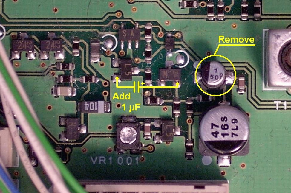
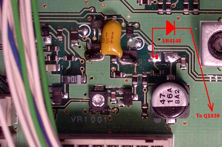
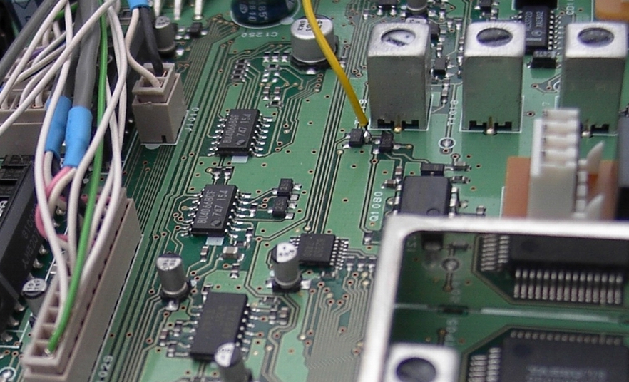
Some two years ago has published first ALC mod of FT847. This modification helps within contests to reduce EMC troubles, but does not removed power peak after TX switch on. The below described modification enlargement fix it. Such modified FT847 is very suitable for drive of additional microwave transverters, however a bit delayed power increase up to setup level may harm on fast CW (semi-BK) traffic on HF bands. But, because we prefer use of thois rig for VHF and higher bands, some 200msec delay between PTT switch on and time, when the adjusted power is observed on the output, is not problem for such use. If you are looking for more precise description of this modification, visit the Czech version of this article and use Google translator. Analysis of Yaesu schematic has been found, that adjustment of TX chain gain (it is in hidden menu) is saved as digital number in the microcontroller and converted into related voltage by 8bits D/A converter Q1093 (M62353GP). This D/A conv. is unfortunately activated not only during "TX ON" but during RX as well. It rise up (because during RX the ALC loop is not activated), voltage on the collector of Q1021 to cca 2,5 V and by this way the TX gain is before switch to TXing setup to max. When PTT is ON, the loop after first overshoot of output power decrease the TX gain to requested output power. However this over peaking may in the mean time damage the transverter input (for instance). Our solution is simple - setup gain of TX chain to minimum during RX and then after switch to TX unblock the ALC, which will continuosly increase the TX gain until the output power reach the level as requested by adjustment of PWR control knob. The modification adds one tantal capacitor, diode (1N4148 etc) and wire interconnection. During RX is is new C1070 discharged via new diode and R1090 to voltage cca 0,3V DC via wire interconnection to RX supply switch. After switch to TX the C1070 will be charged through R1086 (1M) untill reach the voltage, responsible to adjusted power output (cca 0,8 till 2V). Below schematics pics shows the mods (click on the pics):
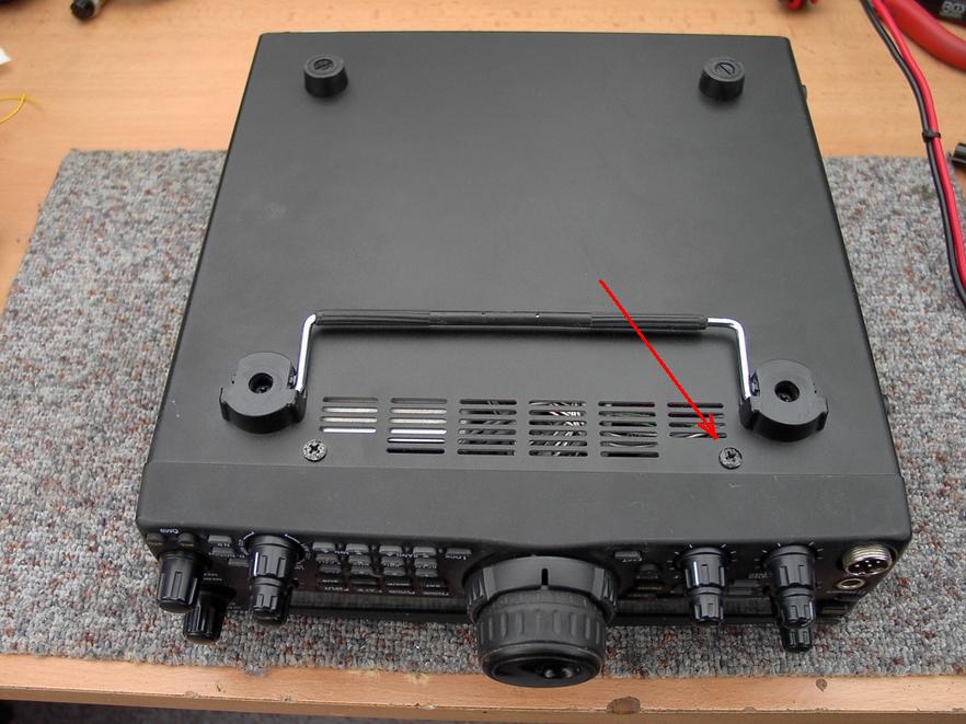
How to do that: Turn the transceiver bottom up and remove the cover:
(this is a modification described here):
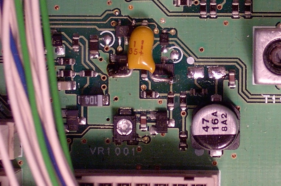
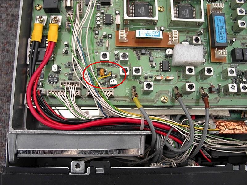
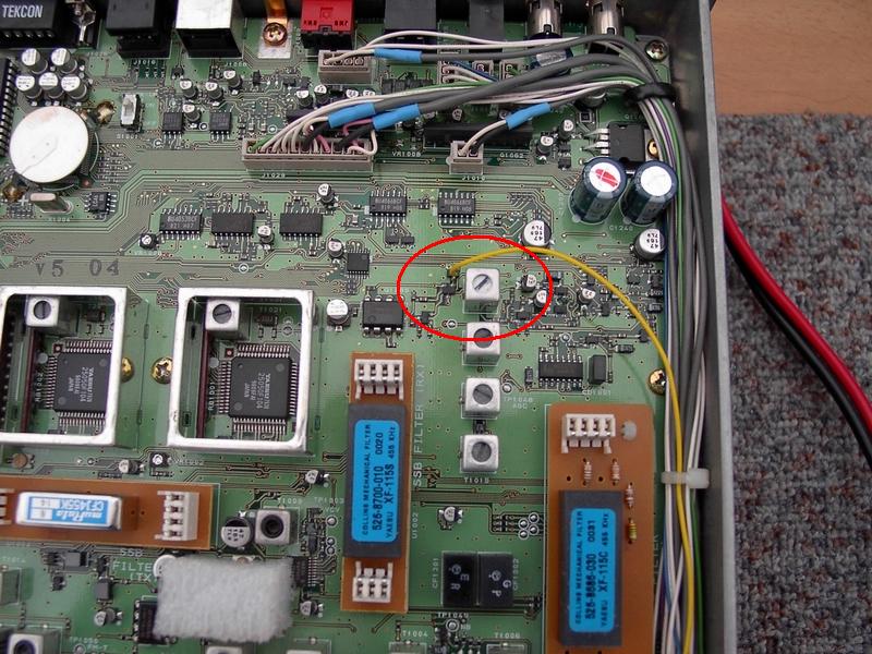
Steps to complete ALC mod (2009 version):
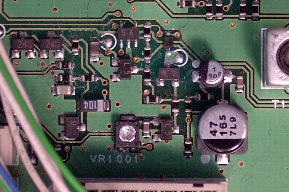
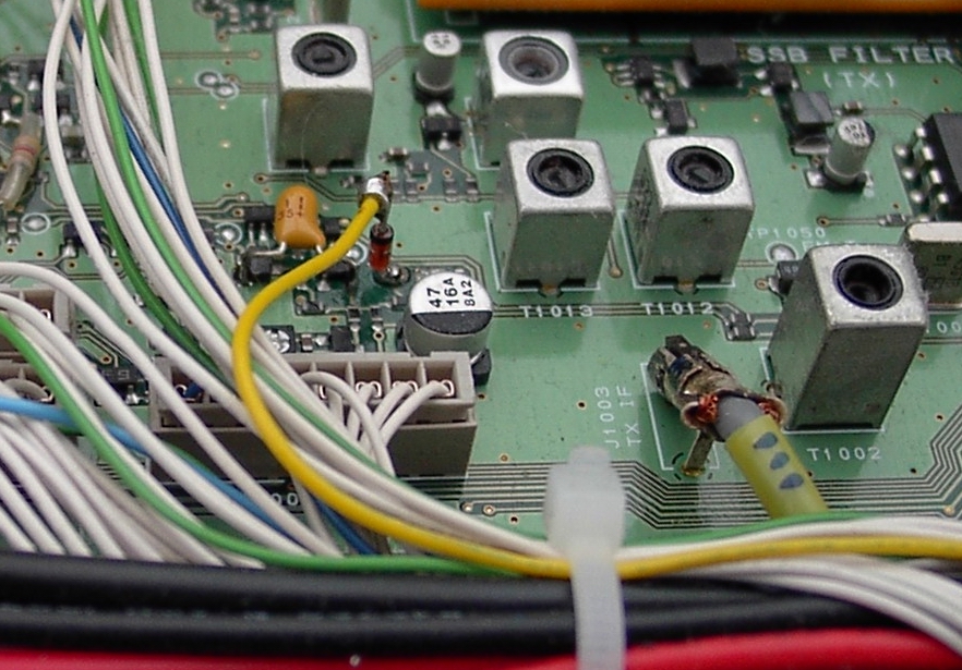
Completed view to the FT847 boards with ALC mods:
Done. All overshot peaks are gone. After PTT on the power within ca 200-300 msec reach from zero the adjusted power output. If you want to decrease this time change the tantal drop capacitor C1070 to less (but not less, than 0,68µF). However, the FT847 after this mods is not great for QSK on HF. But do you need it for such HSCW BK operation? The world of VHF is different... When you have at home FT817 - 857 - 897, it will be probably similar. But theoretic schematic changes were not tested by OK2KKW team. If you need service manuals for better mods realization, you can download it here.
That is. However - keep in mind, that any change in your rig is only at your own risk! Hope to meet you on VHF! 73 by OK1VPZ, OK1TEH and all OK2KKW team And one note for final: After this modification such transceiver cannot work work in satellite mode, when the rig is transmitting paralelly on one band and listen on another. It is logical, because ON status for powering of RX chain is used for lowering of TX power. But it doesn't damage the rig. If you has such trouble, you can fix it by reversing of modification above and use external ALC limitation as described for sequencing of the gear for common operation RX and TX - so called "single exhaust pipe" mode and/or decrease TX gain in the hidden Technical menu, where is possible decrease power at certain band. See links below that article: Internal technical menu (set the gain only such high to operate ALC not more, than cca 3dB). |