|
I will not describe here the CPU part and displaying of such rotator unit - it is a task for other designers, who has software experience - and rather I will focuse to the power interface between CPU and the DC motor of such gear. Why? Because I'm mostly analogue era radioamateur as my collegues of similar age. I hope it would be at least small help for young SW engineers. Well - let me introduce small article of such a bit obsolete unit solution. At firts list of tasks for such "interface unit" between CPU and mechanic parts of rotator:
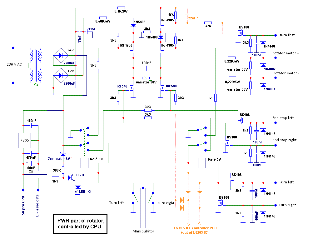
Based on these tasks I made already some 8 years ago rotator unit with Arduino and this ciruits we used in other rotators as well as. Because there weren't and failure yet I decided to describe it here to save a time for anyone, who can use it. Schematic diagram is here:
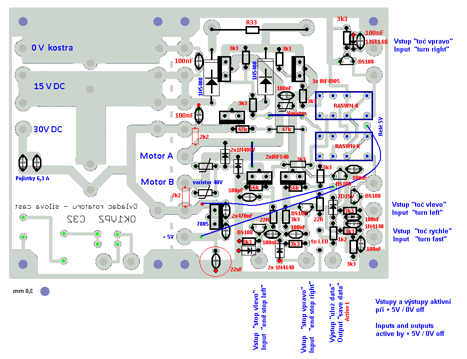
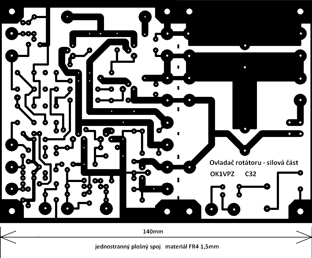
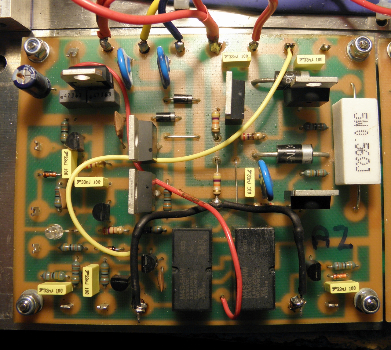
Few comments: usage of power FETs exclude problems of "contacts sticking" well known in control of DC engines. Take care of wrong drawing of FETs (P and N channel), I used rather "bipolar drawing", than correct FET drawing. But type of FETs described in diagram are correct. The PWR FETs have very low resistance in "switch on" status, so there is not needed any heatsinks and the capacity are to big to be it robust against VHF ingress. But the diagram still use two small "signal type" relays, which is the simpliest way to protect such unit against common switch on of both directions channels for example within "booting of CPU". The unit use power supply with two different voltage levels for change between "slow and fast" rotation. However the unit could be used with one level supply as well as (for example driven by OE5JFL controller) and the "fast channel" FET is ON after few hundreds of milisec. when the system is already in motion (see orange dotted lines). Voltage monitoring for data save utilize Zener diode and two LEDs as voltage limiters. In case of supply outage you will get fast L data level for CPU , which is still On from energy of output stabilizer capacitor. One of these LEDs is used for ON monitor light. All other is pretty simple routine connections. Value of the power protection resistors select youself by your DC engine and lenght of cable to it. The PCB is one-sided on FR4 1.5mm thick laminate. GL es 73 de OK1VPZ
click for full size
|