|
It is well known, that bipolar PA intermodulations are closely related to the design of BIAS circuit, particularly to the output impedance of BIAS source. And intermodulations of transmitting way have substantial impact to the interference troubles between stations within VHF Contests. Let's look, how solution of that phenomena could be. Although number of modern LDMOS amplifiers between amateur radio hams growing, unfortunately even more rapidly is growing number of high power bipolar PAs, particularly due to 12 volts powering. And these bipolar amplifiers are more and more often used as driver for high power tube final stage up to kW power level. But these bipolar PAs are not designed for that use - many of them are used more-less only as cheap "pushing" amplifiers for FM mobile operation. For that use they are regularly connectable to the FM radio with unknown output power and the shouldn't be damaged by that. By that reason the are ordinarily designed with BIAS source, which is by growing input power moving toward C class, gain of power stage is decreasing and PA can't be damaged by too high input. Producers are satisfied, because reliability is high and he don't need fix any warranty swaps. Problems are beginning, if someone erect antenna beside his car and start to be active in the VHF Contest... Maybe I would remind, that first rough test, if all the transmitting route is usable for SSB Contesting, is 1 dB compression rule - all the transmitting chain should not be worse accross all modulation curve to be not produce terrible splatters. Key factor for linearity of PA with bipolar transistor is in BIAS circuit and I was focused to improve that. BIAS source must have very low output impedance (around 1 Ohm) and must be able compensate thermal drift of PA transistor to ensure stable quiescent current. Absolutely unusable for linear applications is primitive source with resistor and diode, athough this solution is commonly used for ham radio PAs.
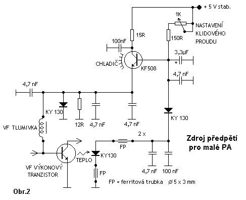
Little bit better is source on second picture, which has lower output impedance and already some thermal regulation skill.
On 3.rd picture is quite well tested BIAS source (several hundreds PAs), designed by author on the beginning of 80-ties. That source was designed for 24V PA with output power up to 30W. This source is long time stable but for present several hundreds W PAs with 12 V powering is not good enough.
To ensure well suitable BIAS power source for high performance 12V PAs for usage in VHF Contests, I made new, high performance, extremely low output impedance BIAS source with high stable thermal loop.
New BIAS source supports output blocking for switching off during reception - external transistor has grey colour. From functional point of view this source is constisting from combination of voltage power supply (LM 7808), parallel shunt regulator, controlled by electronic "zener diode" TL431, controlled by voltage created as diference - on serial connection of two solid state diodes and two resistors (one diode using parallel B-E and B-C transition of power transistor used as thermal sensor), when these devices are driven by few mA current produced from very high internal impedance current source, made by LM317L, which resulted by exactly same voltage change on the gate of TL431, as was the change on T3 due to his temperature drift - and this negative feedback loop keeps quiescent current of HF power transistor on the same level. Schematic diagram is only a part of construction - so here is the rest:
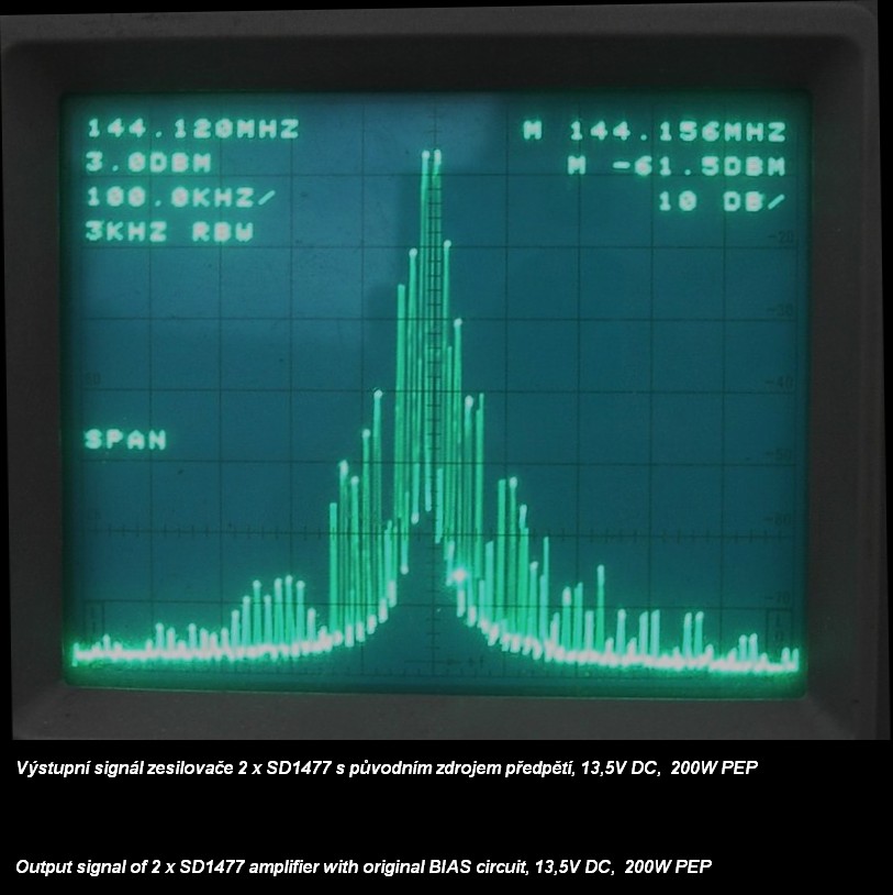
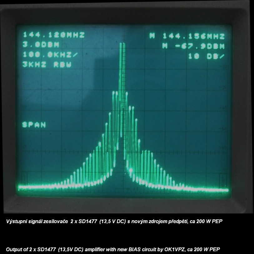
Complete circuit is using simple one side printed board of 30 x 45 mm. For prevention of HF energy ingress is that board placed into metal box about 30 x 45 x 22mm with feed through capacitors. Side of power transistor and LM 7808 is fixing to the PA radiator. To prevent short circuit between cooling strip of LM7808 and power transistor of regulator I would recommend to use transistor in full plastic case TO220 Isowatt - type of transistor is not critical - ordinary NPN transistor like BD241 for at least 3 A current is suitable - between many others for example as well as 2SC4517, MJF18004 etc... To prevent any possible circuit oscillations, T1 PNP transistor should have H21e gain factor below 250. BC556A or BC303 would be the good one. Install tested regulator into PA and adjust BIAS of PA to the around 2% of max. current during full output level. BIAS level is not critical for best intermodulations - what is critical is output impedance of BIAS regulator. During room temperature is UBE about 0,65V, if the PA radiator has around 60°C, it drops to aprox. 0,61 V and opposite, if PA is very cold, it can be even over 0,71V for more-less the same BIAS value (cca ± 20%), due to regulation by thermal transfer between HF power transistor and T3. And what about results of use? Circuit was installed into some italian "no name" PA with two SD1477 transistors in parallel, which should gives about 200 to 250W output power by up to 50W drive and aprox. 23A consumption from 13,8V DC PS. Amplifier was tested with original BIAS power supply (similar to picture 2 above) and then with new power supply.
Results are probably clear... Although this tested PA has now much better IMDs, stil it is not good enough for using of that PA as high power tube PA driver because of bipolar 12 Volts transistor. For comparison look below for pictures of IMD spurious between bipolar and LDMOS PA. Just for note - for local stations spurios should be at least -130 dB for clean reception in second station.
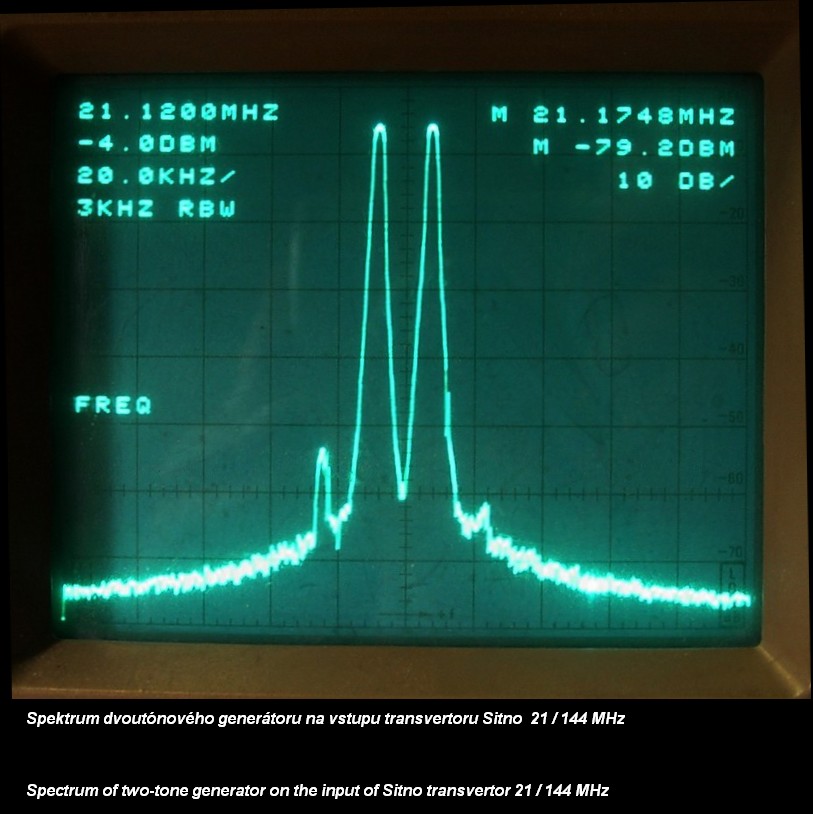
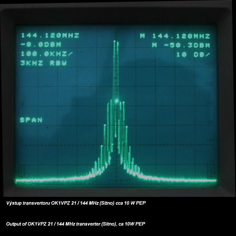
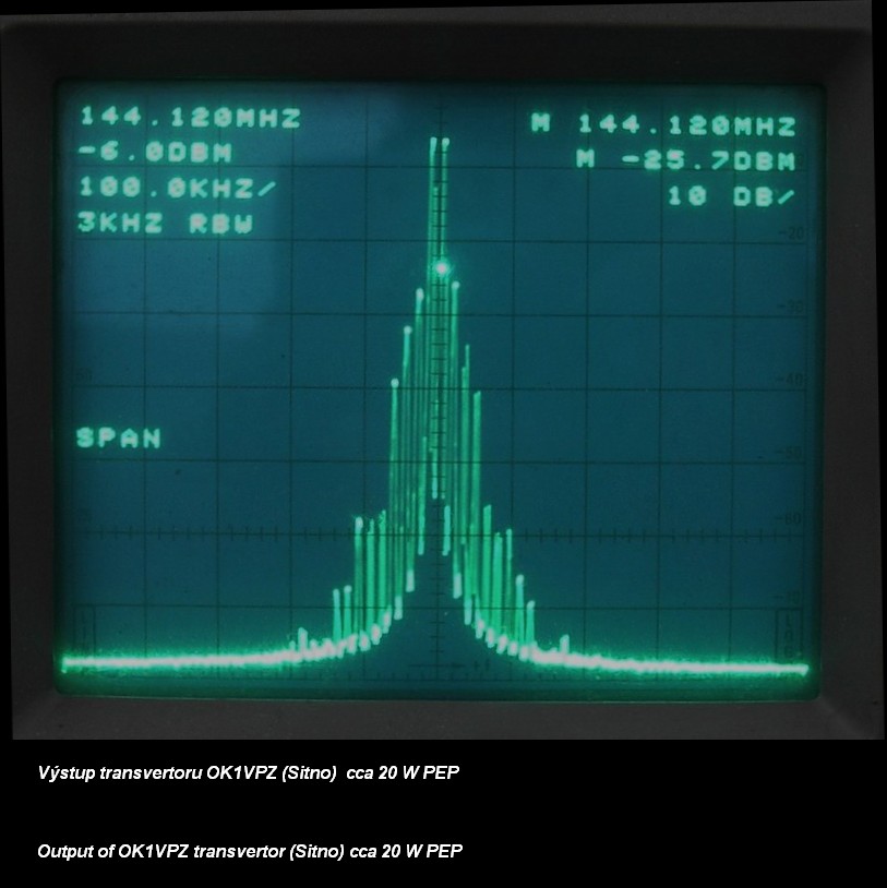
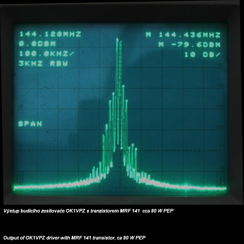
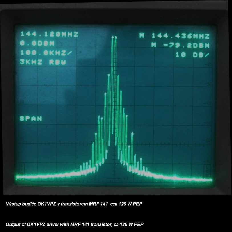
Related links: transvertor 21 / 144 MHz, solid state driver with MRF 141
For final: I hope, that this article gives you conviction, that:
73! ok1vpz
|