|
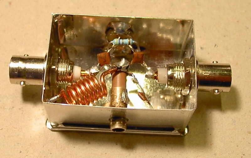
Trap filter for FM radio transmitter signal rejection It's well known situation: we arrived to our well-tested contest QTH and we find there new professional mast with new antennas - not only for GSM, but also for the local FM radio transmitter. Then we switch on the 2m gear and a very strong noise covers all over the band - and even more - the well-known contest station on close frequency, which never made QRM before (or just a little) suddenly produce horrible splatters... What is behind it? Our 2m RX input is heavy overloaded and we have to do something with it. The rejection trap would be the first idea - but how big loss it will create in the RX chain? And how big will be trapping on FM radio frequency? Let us suggest some notch filter solution as described below: Our filter is built in small tinplate box with two BNC connectors, size 30 x 45mm (it can be bought in local shop). Such a solution isn't new and some kinds of this filters have been used for years. First we set the rejection frequency by capacitive trimmer and then we tune resistance trimmer for balance between the suppression of unwanted signal and signal suppression in the pass band which is 144 MHz. After setting optimum combination of resistance trimmer and parallel fixed resistor on the order of ohms we can expect insertion loss of about 0,2 to 0,5dB on 2m and the suppression of unwanted signals around 22 - 30dB. If we accept a bigger insertion loss (about 2dB), particularly if the filter is connected to the preamp input, we can set the trimmer resistance value of the order of 10 to 20 Ohms to improve suppression of unwanted frequencies up to 40dB. The maximum reachable suppression of unwanted frequency is somewhere over 50dB, however insertion loss could rises to about 4dB and tuning of the filter can be thermally unstable. In our ham shack, we have such filter set to 97,2 MHz with insertion loss on 2m about 0,3dB, the suppression of unwanted frequency is around 26dB. If you need to tune the filter at the beginning or the end of the FM radio band, you'll have to change value of a C2 capacitor connected in parallel to the ceramic capacitor trimmer. The schema of filter: The picture of practical realization:
Hope to hear you on VHF. OK1VPZ |