|
Even I don't like "multi-beaming" contest style with more of power amplifiers and many antennas (however each fixed in different direction) due to a huge EMC troubles, requests from other operators pushed me to build such a simple and operators friendly RX antennas switch for such a kind of contest operation. The result of my effort is described below. The mental stress of VHF operator on 144 MHz is enormous, because of very different signal levels (compare HF) of incoming signals. So if operator should control, except another duties, some additional manual switch (or even more switch knobs) for choosing the right RX path from specific antenna several times for every CQ, it would makes OP exhaustion within short time period. Based on our experience with choosing propper receiving antenna I decided to make the RX control as simple as possible. I built it on premise that operator isn't so interested in which antenna he actually use, however he requires pretty fast choosing of the antenna with upcoming response of station after his CQ (with the best signal readibility). The result of RX control is a small plastic box lying on the table by the side of transceiver and telegraphy paddle, with installed low-lift microswitch. The switching over RX antennas is pretty fast as a response on repeated click on that microswitch indeed. On the control box are as well as LED indicators shows activated RX antenna. Coaxial switch is made for receiver switching in between of 3 receiving arrays only, because the higher number of antennas systems from portable QTH is very difficult to build up & dismantle. (Contest stations which have larger antenna systems will solve it anyway, hi.) The controller box is made from iron-plate box with size 90x65x20mm available in GM Electronic shops (CZ) and for this size is designed printed circuit board as well. 3 input and one output HF connectors are BNC 50 Ohm type. As a switch over relay are used 3 ordinary small plastic relays for printed circuit with 2 switching contacts and you can buy them for example under label M4-12H. Even this (and similar) relays aren't primary made for switching of HF signals, in this case they make a good job. The relay is connected with only one pin for signal input, signals from just non selected antennas are grounded and actually selected antenna is connected to output connector. This kind of construction gives satisfactory results, transit attenuation is less then 0,2dB and antennas separation is over 40dB, return attenuation over 20dB, which is for contest operation on 144 MHz more then enough. The relay of RX path is controlled by switching FETs BS170, which are step by step switching over the CMOS CD4017 decoder. Printed circuit should be constructed on double sided clad laminate FR4 with thickness 1,5mm. The construction isn't difficult and all is working after first switch on. Data for home made RX switch construction follow:
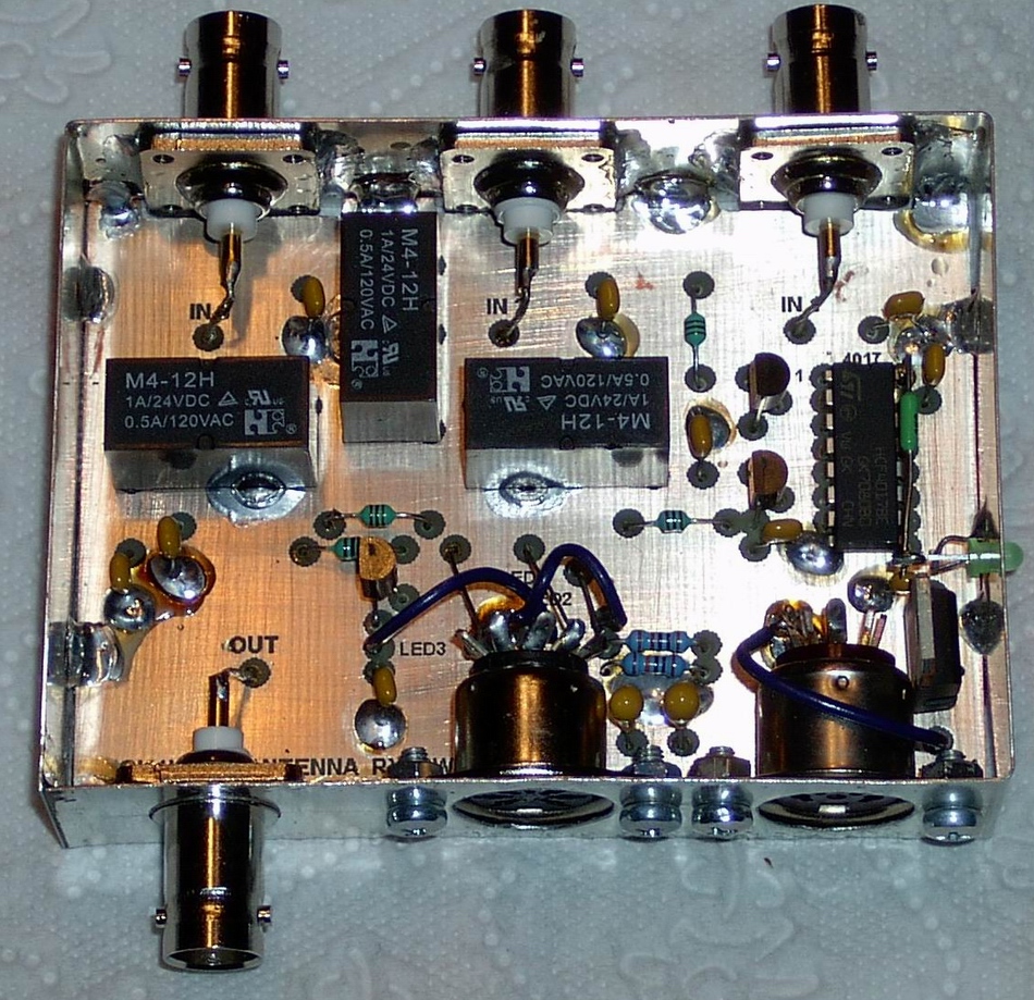
Scheme Printed circuit of switch (Side A) (Side B) Inserting scheme View on final switch without cover
After your clicking on the pictures you'll see them with full resolution. The boards of printed circuits for this construction you can order here. CU on VHF! OK1VPZ |