|
Albeit YAESU launch production of FT847 already in the end of last century, this gear still has place on the table of many VHF operators. Probably not so much for some extraordinary RF performance, because characteristics are rather average, but for ergonomics: this transceiver is not so small or big and almost all of important functions are directly switchable from the front panel without use of some lower level “hidden” subfunctions, like in case of smaller siblings FT857 and 897. Within a time amateur radio operators fixed some weak points, like ALC splatters, separate RX inputs installations, loud ventilator, burn out power switch and more. Even operators were able exploit timeless design of FT847 and activate full performance operation in the 70MHz band, what improve popularity of this transceiver. Unfixed troubles still stay missing measure of tune deviation in case of RIT use and PWR switch contacts burn out. Anyway there are plenty of modifications of PWR switch described on internet, however I did not found fixation of another common trouble of FT847: when the supplying of the rig is provide from the PSU with electronic current limiter, the transceiver during switch on sequence produce strange sound due to short clattering of the input power relay, because charging of big elko capacitors overload electronic current limiter in PSU, which creates oscillation of PWR circuits in FT847 – and it creates burning of PWR switch contacts as well as may damage the PWR relay in the transceiver. Solution of it has two steps:
first
option is PWR switch modification. The switch has two contacts and the most
simple is parallel connection of both of them together. However it is not the
way, how to fix it for long time. Much better is use of solid state switch, in
my case by use of
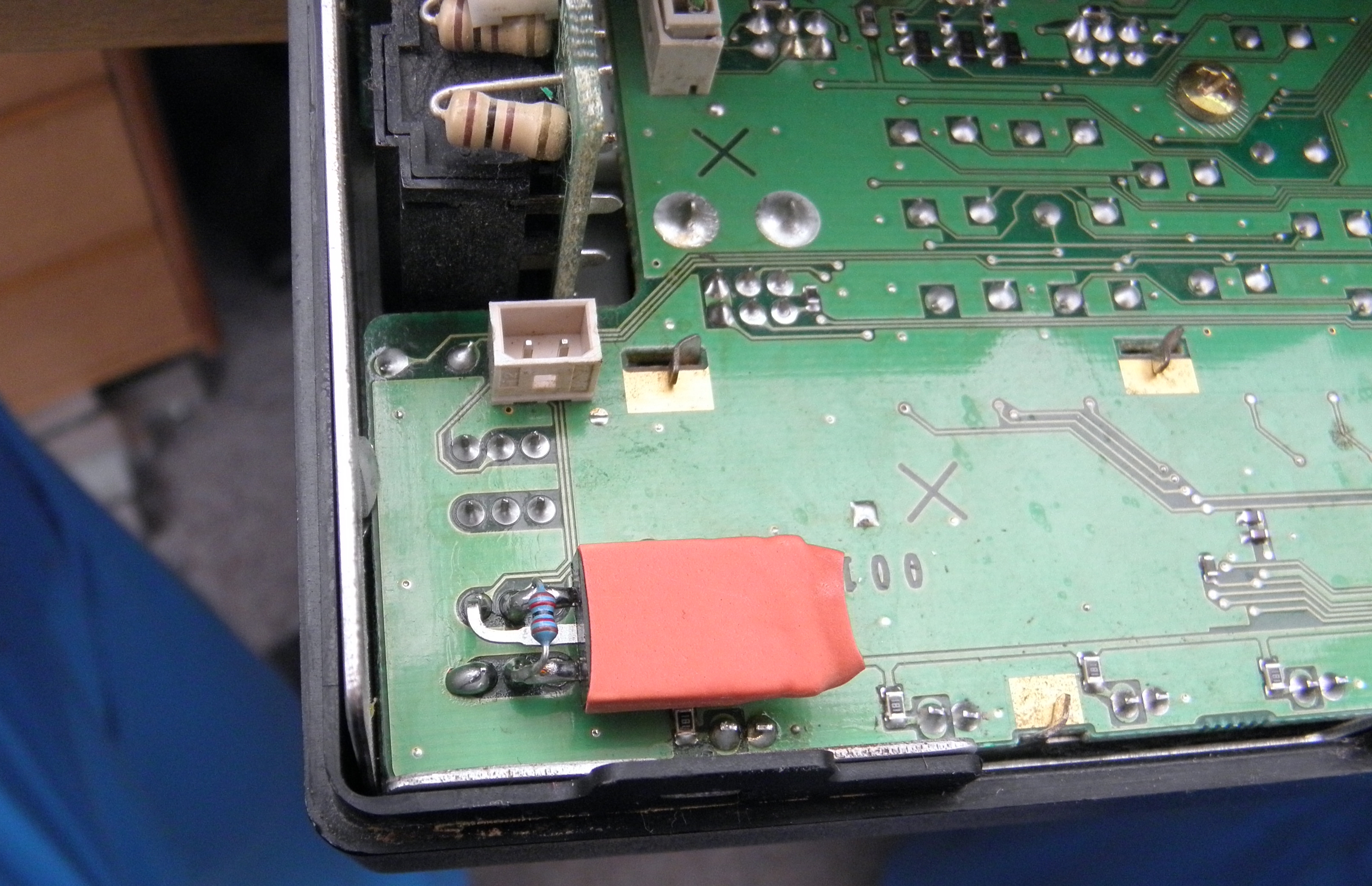
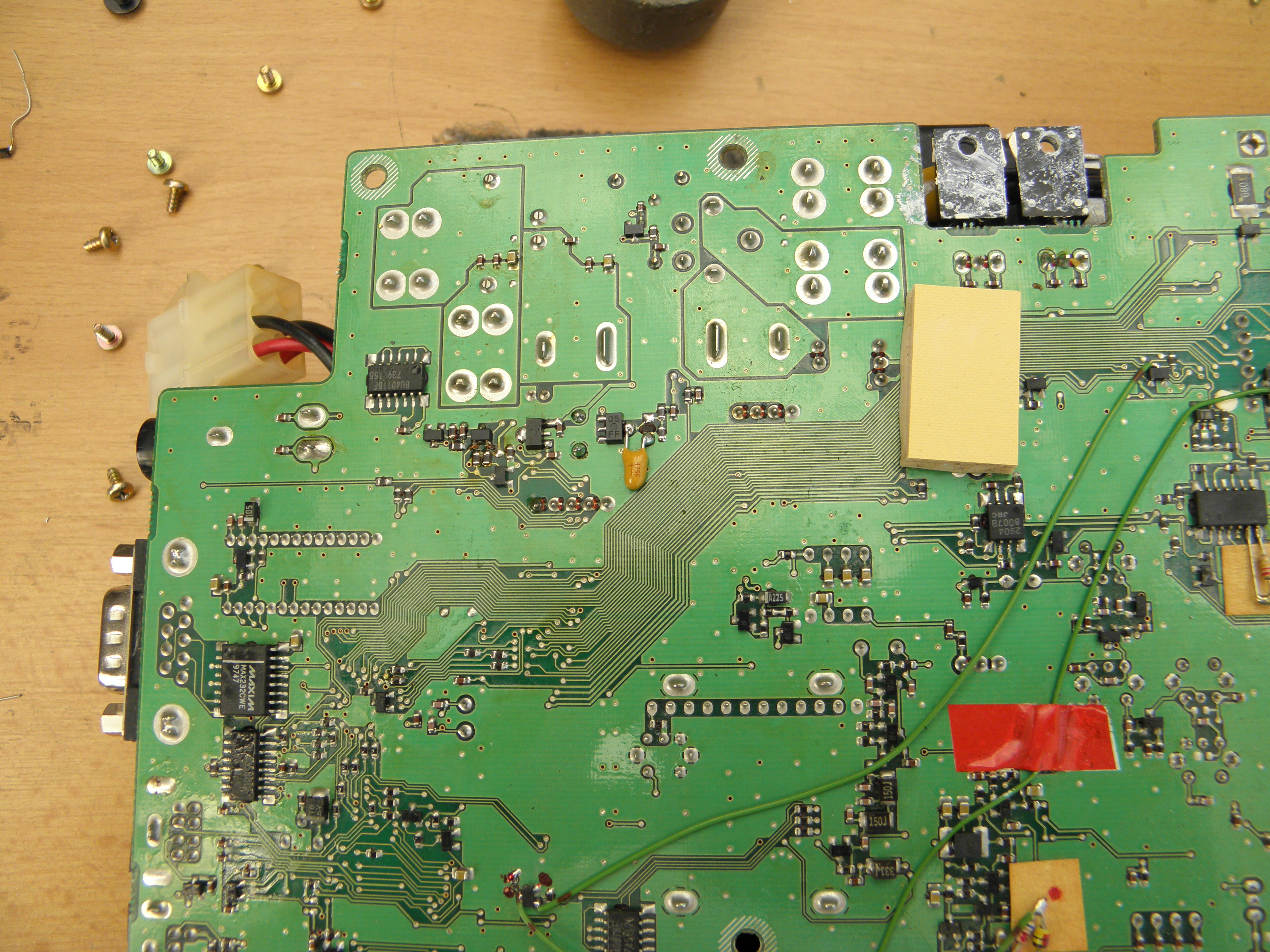
IRF4905 P-FET device by this way:
(the transistor as well as 3k3 resistor you may place and sold directly on the front panel PCB - however on the rear side.Click for detail.)
I believe, that such modification will fix all of your bad feelings due to FT847 oscillation within switch on sequence. 73 de OK1VPZ |