|
I'm quite sure you have such experience as well - within some VHF Contest you suddenly observe, that your receiver is deaf and after some investigation the reason of it is clear - transistor in the LNA has lost all emitter's arrows... The next job is the LNA transistor replacement, but the trouble is repeated already within next contest. Such problem is usually result of unsuitable time sequence of switching between receive and transmitting, where due to different delays (for example by mechanical movement of relay parts) may happen conflict between beginning of transmission (e.g. by push down of key), although the complete transmitting chain is not ordinary switch on yet, or in opposite within switch down from TX to RX, when antenna relay already going to RX, but due to another PA relay mechanical delays the TX is not calm down yet and last dot of TX CW power (or roger beep) may still be observed. Result of such unpredictable transition status is not enough isolation between RX and TX chain in the antenna relay (because this relay is just moving) and the peak of power transported across the switching antenna relay may easy destroy input transistor of LNA or even receiver front end. Even in case, when different delays in our TX chain were adjusted properly and such trouble was not observed for years, change of transceiver or transverter may create change of the whole chain delay and when we want (for example) use older PA together with new transceiver (which has not mechanical, but PIN diode RF switch inside), or even when the SW delays of transceiver is setup to QSK, the trouble of LNA damage or in the worst case even antenna relay may be destructed. Substantial part of solution of such unlucky situation is an installation of appropriate time sequencer into each final stage PA, which is used. Each important parts of TX/RX chain will be then controlled in certain predicted time steps, what ensures, that the above described conflict between TX and RX ways will be eliminated. And because such additional control circuit shall be installed into any present PA, it should be quite universal in the interconnection and covering of all variants of usual control designs and on the top it must be not very large. In the OK2KKW (OK2A) Contest club we are using the following design:
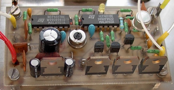
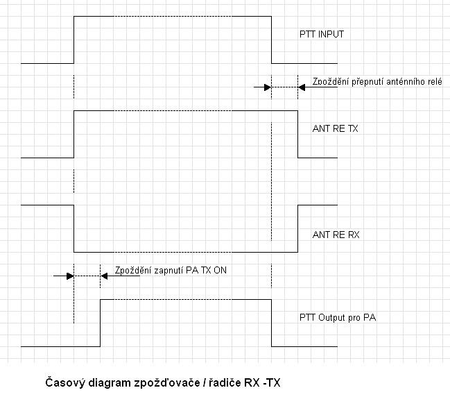
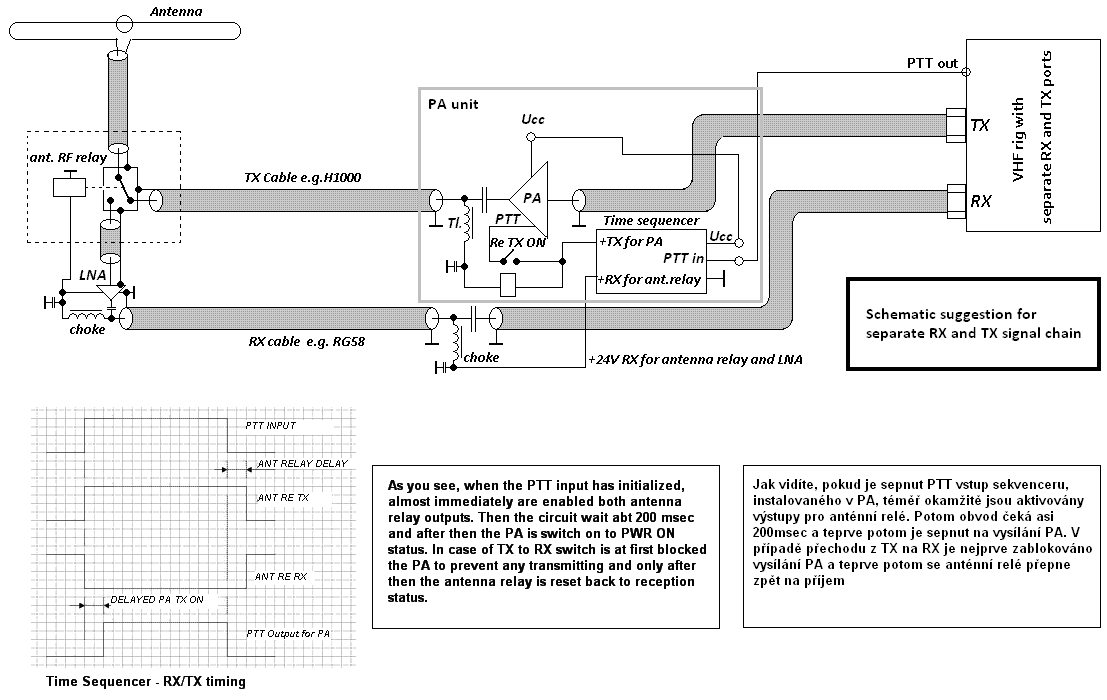
The circuit uses cheap one side epoxy board of 45 x 80mm size. The supply is between 13,8 to 28V DC and on the PTT input it accepts both polarity of PTT control - it mean usual grounding as well as switching to TX by insertion of positive voltage 9 to 24V. On the board output are three power switching transistors for control of antenna coaxial relay and for control of PA installed relay, which will activate TX and/or disable blocking of PA during reception. These outputs are available again in both positive as well as negative logic and based on board interconnection, which can be on 12 or 24V control level. Beside it, the board has control output for next unit controlled by grounding based PTT. Frankly - all of these outputs configuration are prepared for controlling of connected circuits, which can have both positions, some of them are initialized during TX, the other during RX status. On the next picture you may observed time sequence graph during change between RX to TX and opposite.:
As you see, when the PTT input has initialized, almost immediately are enabled both antenna relay outputs. Then the circuit wait abt 200 msec and after then the PA is switch on to PWR ON status. In case of TX to RX switch is at first blocked the PA to prevent any transmitting and only after then the antenna relay is reset back to reception status. During fast CW morse traffic this sequencer unit will "cut off" few first letters, but such operation trouble is for sure better, then damage of LNA or RX input and lost of time in the contest to fix the failure. On the top, the delays can be changed by change of time constant of R7/C3, resp. R13/C4 combination. If are you using by 12 volt controlled antenna relay, we suggest to fix the 7812 stabilizer to heathsink or use 24 voltage control and connect 12 volt relay with appropriate rezistor in series (between relay coil and ground). Darlington transistors TIP125 (or similar PNP Darlington type switching transistor) is usually not needed to fix to any heathsink. The board of sequencer is good to place somewhere in PA close to input PTT connector, where is not presented high level of RF field.
Next note: in case of 13,8 supply voltage please use LM7809 instead of LM7812 stabilizer. In case of lack of TIP125 Darlington tranzistors they can be replaced by IRF9540 FETs, but between their source and gate must be connected (from the connection side of PCB) additional 3k9 rezistor. This sequencer is generally better, then any sequencer uses mechanical relays, because use of mechanical delays in the sequencer create unstable and unpredictable timing. The next stage of sequencer design is use of microprocessor chip, but because this sequencer is so simple, few elements more (compare microchip style design) may balance necessity of microchip programming. However, what you will prefer is just up to you. For final:
73! OK1VPZ Click on the picture for full size.
|