|
A Home-Built Parabolic-Type Reflector for 1296 Mc [1961] Moon-Bounce Capability for $99.98 or Less BY FRANCIS LeBARON, W1TQZ
With all the current interest in moon-bounce efforts and satellite communication, the idea of an inexpensive parabolic-type antenna and mount seemed worthy of investigation. Considerable discussion and a few pads of paper later the following design evolved. The basic criteria in order of importance were (1) Cost; (2) Ready availability of components; (3) Ease of fabrication; (4) Frills and refinements. With this approach, most of you can probably improve on some of the details, particularly if you have access to more sophisticated forming equipment and welding. Both have been avoided almost entirely in this design, so that any amateur willing to expend the effort and cash should be able to build this antenna system. Parabola vs. Cylindrical Reflector Strictly speaking, this is not a parabola, but a slightly distorted cylindrical reflector. Consultation with W1FZJ brought out the point that a cylindrical parabola (section one way a parabola; at right angles to this a straight line) is only slightly inferior to a paraboloid of revolution, and the former is oh-so-much easier to construct. Mathematical investigation brought out the fact that for a focal length of ten feet and a diameter of about 16 feet, the maximum difference between a cylinder segment and a cylindrical parabola is only about 0.8 inch! At 1296 Mc and below, this is scarcely significant. A parabola is a curve each point of which is equidistant from a point called the focus and a line called the directrix. Mathematically it is described by the equation y2 = 2px. This is roughly plotted in Fig. 1A. If we solve this equation for the focal length and up to the diameter listed above, we get the first two columns of Table I. Now a circle is nearly equivalent to a parabola for a short segment. The effective focus of a segment of a circle is one-half its radius. See Fig. 1B. Therefore, let’s compare a circle of 20 foot radius with our parabola. The equation for the circle is y2 + (x-p)2 = p2 (You experts in analytical geometry check me!). The results are plotted in Column 3 of Table I. The difference between Columns 2 and 3 is tabulated as Column 4. This is the error resulting. From this it is apparent that the maximum range of error is only 0.84 inch. At 1296 Mc. the wavelength is about 0.23 meter or approximately 9 inches. Therefore, we have an error of less then one-eighth wavelength, or supposedly not enough to cause any cancellation, though the gain may not be up to the theoretical maximum. The layout and checking obviously are much easier with a circle.
You bears for punishment may proceed with the layout and use the error figures in Table I as offsets from the circular arcs to get a true parabolic section. Good luck to you! More conservative souls will he content either to leave well enough alone at a true (as you can construct) circle or a flattened approximation, setting each tip of the main arms 1/2 inch back of the circular position. This is in effect using each half of the reflector as a separate unit aimed at a common point, and it works out to an error of about 0.3 inch. See Column 5 in Table I. The Moon-Tracking Mount
The mounting is an equatorial type; that is, to follow a celestial object such as the moon it is necessary to feed in only compensation for the rotation of the earth (hour angle) for all practical purposes. An altitude-azimuth mount would be easier to construct, but how many of you have the requisite computer and fancy aiming drives required? We’ll stick to the equatorial mount. To follow an artificial satellite is a problem with either type mount. Procedure for construction of the mount is more or less like the classic recipe for rabbit stew; first get the automobile rear end! The remaining mechanism is built around it and to some extent from it. Any rear end can be used, such as a Buick, that is built with a torque-tube construction, or no universal joint at the differential and a tubular construction next to the differential. If possible, take off the differential cover and check that the pinion gear and ring gear are in decent shape. Have a friend rotate the shaft, and check backlash and see that the pinion gear does not move up and down or in and out. If it does so, the bearings will have to be taken up, or you’d better find another one.
Pick one that uses bolts, not studs, to
hold the wheels on. Police up some bolts at least 1 + 1/4 inches long
under the head, to fit the wheel-bolt holes. Find an old universal joint
or other splined coupling to fit the transmission end of the drive shaft.
A couple of bicycle chains, sprockets, and two or more reasonably
serviceable roller skates, and you are ready to talk dollars to the junk
man. If you see a worm-gear drive, got it, too. If you are on good terms
with the yard man, and do some of the work involved in getting the
material together, you may get the works for $15 or less. The rear end
should be used with as much weight as possible removed. We removed one
complete brake drum, brake mechanism, both shock absorbers and associated
parts. To do this it was necessary to pull the axles, a short but messy
operation. Drain the oil, open the differential cover, remove the safety
pin from the spider-gear pin, remove the spider-gear pin, remove the
spacer block, slide the axle inward enough to clear the locking
horseshoe-shaped clips, remove the clips and slide out the axles. Remove
the unwanted parts. Save the brake drum removed, as this will be the
hour-angle drive pulley. The other brake assembly is left on as an
elevation brake. Reassemble the axle and other parts. Mop up the inside of
the case.
The differential (axles) must be locked with an absolutely rigid connection from one axle to the other. Just locking the gears is not enough, as there will be 5 to 10 degrees slop in the gears and splines, or enough to distort the dish badly. At the same time, the wheel-bolt holes must have the proper relationship from one side to the other. Also, the axle as a whole must rotate freely for the latitude drive. We recommend that you take the thing to a welder, and carefully line it up by supporting it on two bolts in each wheel hub, with these bolts resting upon some parallel supporting edges. Then have the axles welded to the spacer block in the differential. Clean out the welding splatter and re-oil. Adjust for minimum drive-shaft slop if you wish, and put the cover on. An unchecked alternative would be to clean both axle splines and the gear splines very carefully, and attempt to lock them and the spider together with Devcon Plastic Steel or similar material. The Wooden Supporting Structure The drive mechanism described above is mounted between two T-section wooden arms. To make these arms, a 10-foot sheet of k-inch plywood (see bill of material) is ripped into four 1-foot widths. These are assembled to make two T-sections 10 feet long. Unless you did a better job than we, use the two original machine-cut edges for the joint, taking advantage of their accuracy. Use a good grade of glue, and put in 1+ 1/2 inch screws about every six inches. Temporary clamps, or perhaps blocks, will make the alignment easier. Let the glue set sufficiently before continuing. Measure 3 feet along the center line of one face and mark. With this as a center, place the brake drum on this face, mark and drill the holes for the wheel bolts. Use the brake drum as a jig to insure accurate alignment. Remove the drum, clamp the other T-section face to face with the first, and drill the holes. If you have aligned everything properly so far, when assembled to the rear end the arms will be parallel. But don’t assemble them yet. Now mark any other places needing clearance, such as the axle ends and the small bolts holding the brake drums on. These spots must be drilled or chiseled into the plywood to allow clearance for the parts. Reflector and Frame
If we splice the arms with the concave faces 1/2 inch away from the ends of this curved piece, while the center joint touches the center of the piece, we have the corrected curve of Column 5, Table I. The joint between the main arms and the dish arms is the critical one. The ends of the circular segments do not butt square, and a filler piece should be made. This piece should also be plywood to prevent distortion from the differential expansion from weather extremes. All pieces must be assembled accurately. If you do not intend to move the dish to some other site, these joints may be screwed together and glued at final assembly. Our dish was bolted only; we hope to work moon bounce from the state of Vermont with it eventually. The curved arms arc set forward of the end of the T-sections by about 1+ 1/2 inches, clamped, checked with the curved remnant as explained above, checked for equal distances from tips to end of main arm, and bolted or screwed in place. The first assembly is then turned over and the second made on it as a guide. Match mark the pieces and disassemble.
Carefully measure between the mounting surfaces of both wheel hubs. Adding 2 inches to this measurement, make a crude jig for this total, to allow drilling the aluminum tubes which will serve as supports for the reflecting surface. Use a drill a few thousandths smaller than the aluminum nails. Be careful to get the holes reasonably parallel. Take the curved arms and mark them every 16 inches along the front edge. About 1 inch in from the edge at each mark drill the holes for the nails that serve as anchors for the wire lacing. At each end of each curved arm cut a notch to accept the heavy tubing, which should project just 1/2 inch above the surface, if you are doing a real fussy job, cut the notches to put all elements, including the heavy ones, flush with the surface. Align the two corresponding arms from one side of the dish the proper distance apart and nail the tubing, maintaining alignment as best yon can. Wire down the tubing with about four turns cross laced. Now cross-wire from under supporting tube 1 (Fig. 3) at the right arm, across to tube 3 at the left arm, crossing over tube 2 at the center. Wire back similarly from tube 1, left arm, to tube 3, right arm. Repeat the process for tubes 3, 4 and 5, resulting in two sets of cross-bracing, as seen in Fig. 3. Square up as well as you can. Make the other half of the dish frame. Check and double-check that you have the right arm in the right place. Take the four 3/8 inch soft tubes and carefully bend them to agree with the convex gage. Cut them to fit between the ends of the larger tubes, passing in back of the 1/2 finch elements. See Fig. 3. Drill holes through the ends of the 3/8 inch tubes and wire all joints. Check the alignment of the whole frame by eye. The frame is now ready to cover.
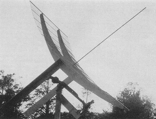
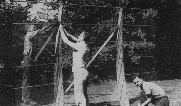
We tried running the 1/2 inch mesh of the hardware cloth both horizontally and vertically, and concluded that horizontal is the better. Cut two pieces 4 feet by 12 feet. Lay them on top of each other, inside curve facing inside curve. Lace one pair of edges together with No. 22 wire. Carry the assembly to one frame and carefully open it up in place. Align the top edge of the wire mesh with the top 7/8 inch tube. Wire it in place, working from the middle in both directions. We used two turns of wire every 6 inches, approximately. Carefully stand the frame up, brace as seen in the photograph, and wire on the surface, one element at a time, working from center to edge and from top to bottom. Use your judgment and keep things aligned as well as possible. Correct any errors forward of the true surface by wiring them back across the hack of an arm and to another error or to the face side of the adjacent arm. Final Assembly For the mounting, see Fig. 4. The rear axle or latitude axis should be at least 10 feet up if you wish to be able to aim at the horizon, east and west. Put at least 3 feet of post below the ground. Take the best and strongest roller skate and close it up to the shortest wheelbase possible. This probably isn’t far enough, so figure out how better to close up the make that you have. Some types can be disassembled and put together backward with a shortening of about an inch. These wheels are at the upper end of the assembly and must sustain the total weight of the antenna and the mount. The wheel axles and the center of the torque tube should form no more than a 90-degree angle, as shown at the upper right, Fig. 4. As a last resort, build your own frame to hold the wheels. Cut off the top of the main mounting post to an angle equal to your latitude. Secure the skate or bearing assembly to this slanted surface. Two 4 inch No. 14 screws or larger should hold it. Bore about a 1 inch hole crosswise through the post, in the center, about 6 inches below the slanting cut. This is for the safety chain. Fabricate the lower bearing assembly as shown in Fig. 5. The misplaced brake drum rides on these bearings. Check their fit and clearance against this drum. Allow for nearly 1/4 inch deflection and wear for the thrust bearing, before the drum bears on the wood. Cut out for the clearance if necessary. Use washers under all the bolts and nuts bearing against the wood. Make sure that the heads of the 1/2 x 2 inch stove bolts will clear the brake drum. The slots in the plywood and those in the 3 x 4 inch timber give you about 3 inches of adjustment.
Secure a good sturdy ladder to one side of the main mounting post. Fasten a block and tackle or other lifting equipment high enough to lift the rear end assembly into place. Don’t forget you are dealing with comparatively heavy weights; three hundred pounds falling from 10 feet could easily be fatal. Keep out from under! Lift the rear-end assembly into place. Bolt safety chains around it before releasing the hoist at all. Then slack off a bit and jockey the rear end into approximate position. Secure the hoist.
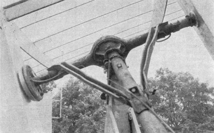
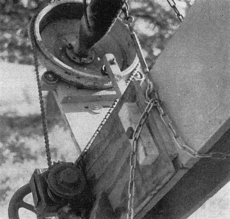
Toenail the 3 x 4 inch piece to the pole. Nail on the long diagonal braces and bottom tie braces, with the 3 x 4 lined up to give the proper support to the lower bearing assembly. Note that the nails are loaded sidewise, not in direct pull out. Large screws would be preferable if you have them. Adjust the alignment to point the torque tube at the North Star. Secure the bottom assembly. Add the lower safety chain. Tie the axle to the pole so that the torque tube cannot revolve on the upper and lower bearings. Recheck that everything is properly secured, and then release the hoist. Remove the hoist and the ladder. Carefully rotate the axle until it is horizontal. At this point, if you have the parts it would be wise to add the drives. Their details are up to you and what you manage to promote in the junk yard. Mount the latitude drive on the lower bearing brake drum, as the most convenient spot which maintains constant angular relation to the drive shaft, as the assembly rotates about the polar axis. The universal joint and the sprockets and bicycle chain were used here, as can be seen in one photograph. Mount the hour-angle drive at some convenient point on the supporting structure. As can be seen in the photograph, both our drives are chains driven by worm-gear reducers. The hour-angle chain is bolted to the brake drum. With the drives in place you can position either axis to suit the work to follow. We did it the hard way with ropes, the drives coming after. Having drafted a reasonably husky bystander, and with the latitude axis horizontal, position and bolt the two wooden main arms. They should be parallel. Using the latitude drive, invert the arms so that their long ends are up in the air. You are now ready to mount the top piece of the dish and the main crossbar for the feed mast. Bolt these in place. The curved arms should be parallel. Now rotate the dish about the latitude axis until the main arms are about horizontal. Swing the other half of the dish into place and bolt together.
Carefully sight the end 7/8 inch supports, and make sure that they are parallel with the center one. Then string a piece of No. 22 wire from tip to tip of each curved arm, on the netting side of the end supports. This wire should be 18.7 inches from the center supports, if you arc using the half-inch set back, or 19.2 inches for a true circle. For you hardy souls making a true parabola, the distance is 18.5 inches. Back guys from about halfway out the arms to a point behind the axle a few inches will open the parabola, while tightening up on the feed-support pole will deepen it. The actual radiating elements and other electronic details we will leave to the electronic experts. Construction to this point has been the job of the Mechanical Engineering Department. Any takers? Thanks are due various members of the Rhododendron Swamp V.H.F. Society and others, some of whom arc seen in the photos. Without their help, the project literally would never have gotten off the ground. Particular thanks to Sam Harris, W1FZJ, Fred Collins, W1FRR, Southard Lippincott, W1DDN, Verne Robertson, W1EGE, Dave Walker, Dick Packard, W1HLI, Jim Grandfield, K1KXQ, and Mrs. W1TQZ.
QST April 1961 for OK2KKW web rewrote and edited Matej, OK1TEH in year 2010 |
 Find
a reasonably level place where you can get at least 20 feet from the
corners of the sheet of 1/2 inch exterior plywood, laid flat. With a 20
foot radius, mark off an are of better than 8 foot length. Then following
Fig. 2, mark the sheet of plywood. Use the same center for all arcs,
shifting the plywood toward the center and aligning it with the original
marked-off are. Cut these arms out. If you are really skillful and
ambitious you can do it with a common hand saw, but a saber saw is a lot
better and easier. The convex piece of waste forms a good gauge.
Find
a reasonably level place where you can get at least 20 feet from the
corners of the sheet of 1/2 inch exterior plywood, laid flat. With a 20
foot radius, mark off an are of better than 8 foot length. Then following
Fig. 2, mark the sheet of plywood. Use the same center for all arcs,
shifting the plywood toward the center and aligning it with the original
marked-off are. Cut these arms out. If you are really skillful and
ambitious you can do it with a common hand saw, but a saber saw is a lot
better and easier. The convex piece of waste forms a good gauge.