|
432 MHz EME with a small
antenna [2010]
by Andreas Haefner, DJ3JJ
A lot of people
would like to do EME but think they need a big antenna for this. In this
article I show how to build up a small but competitive EME antenna and
what is important to be successful with a small station.
I chose:
1. The max. possible boom length that works without mechanical support and
ended up at 3.4m (4.9wl) with a 20 mm x 20 mm x 1.5mm boom.
2. Solid aluminium elements with diameter of 6mm to reduce wind load and
allow easy screw fixing.
3. Elements mounted on top of the boom with commercial element holders.
4. Z = 50 Ohm to use an easy to build straight dipole.
5. Symmetrical dipole made from ½ inch cellflex cable.
What antenna design was first choice ?
For the first time I started with a well known design from
Martin, DK7ZB. I
built 4 x 13 element
ZB7013 with a boom 3m (4.32 wl) long and about 20.5
dBd gain. Stacking distance were 1.45 m horizontally and 1.2 m vertically.
I could work some big guns like DL9KR, VK3UM and HB9Q but was not able to
copy 8 yagis stations and below or own echoes.
Checking RX performance by sun noise
I started to check my RX performance by measuring sun noise. With my 4 x
ZB7013 yagis and very short cables to the 4-way splitter i could measure
4.5 dB sun noise at a solar flux index SFI of 68 and elevation >30°.
This is a very low number for a 4 yagi system on 70 cm. If you take
the
VK3UM EME Calculator and take a 4 yagi group with a gain of 20 dBd and a
preamp of 0.5 dB NF you will get a result of about 8 dB sun noise. So what
is the reason for loosing 3.5 dB RX performance ?
How to find out the reason for a low rx performance
I was looking for the reason for this low sunnoise and made a simulation
of my 4 x ZB7013 compared to 1 x EF7015.
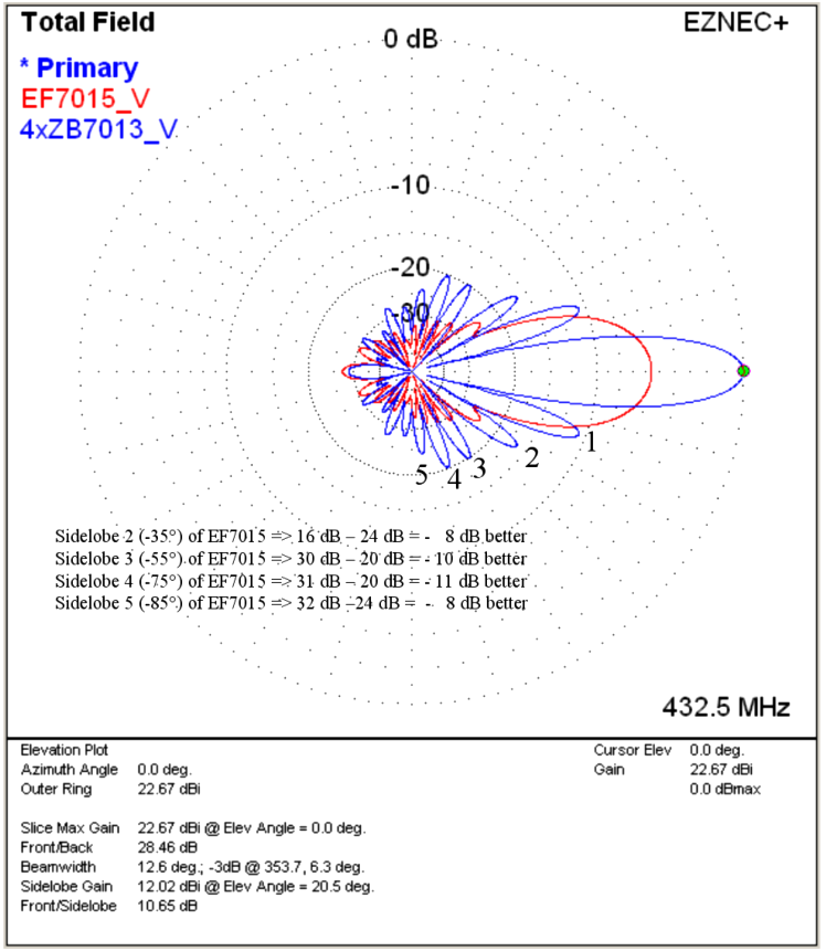
Fig 1
In fig. 1 you can
see the vertical diagram of 4 x ZB7013 compared to 1 x EF7015. As you can
see the 1 x EF7015 has a 5.5 dB lower gain but on the other hand this
antenna has a 8 to 11 dB better side lobe suppression of all side lobes
above 30 °. This is the reason, why the single yagi has a much lower
antenna temperature. All the noise from the ground is kept away much
better from this antenna.
This means with 1 x EF 7015 you can copy EME signals with nearly the same
signal strength as with the 4 x ZB7013 only because of the clearer
pattern.
I build up a single EF7015 ( Fig. 2) and could measure a sun noise of 4 dB
@ SFI 70 with the same preamp I used before (DJ9BV MGF1302, 0.5 dB NF @ 19
dB gain). After that, I was listening to OH2PO via the moon and did get a
very nice CW audio copy with very low audio noise and much lower QRM from
cable TV than anytime before. See Fig. 3
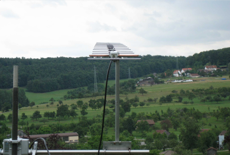
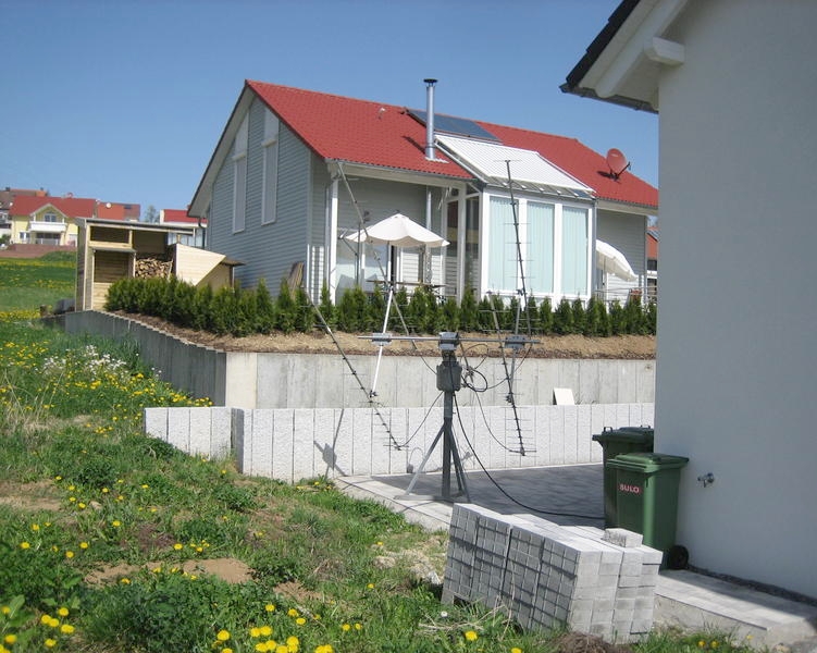
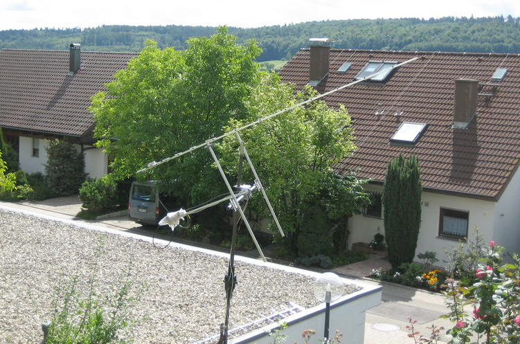 Fig. 2 - Single
EF7015 for EME Fig. 2 - Single
EF7015 for EME
Fig. 3 - 70cm EME signal from OH2PO on Spectran received with a single
EF7015 yagi
Further
increasing the RX performance
After this positive result I assembled 3 more yagis to a group of 4 x EF
7015. The vertical stacking distance was1.4m and horizontal stacking was
1.45 m. As you can see in fig. 4 this increases the gain by 5.81 dB from
17.13 dBi (15 dBd) to 22.94 dBi (20.8 dBd). The suppression for sidelobes
3 to 5 reduces from -30 dB to -25 dB which is no an issue as long as
sidelobes are below -25 dB. If you reduce vertical stacking from 1.4 m to
1.2 m you will have only 0.24 dB lower gain but first sidelobe will be
reduced from -11.5 dB to -16 dB and sidelobes 3 to 5 will be again at -30
dB level. This action is always interesting if you have QRM from below
(PC, WLAN etc.) and need a better QRM suppression.
If you check your
RX performance with 4 of these yagis you should end up with a sun noise of
10 dB and SFI 70. This is really a very good result for such a small
antenna group and gives you the possibility to copy your own CW echoes
with about 500 W at antenna under fair conditions in moon perigee.
More details
about this antenna you can find at:
http://www.yu7ef.com/ef7015.htm
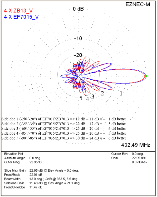
Fig.4
1.4 m x 1.45 m x 3.4 m eme antenna group is still to big
If this antenna is still to big for your personal situation there is
another smaller design available.
Its dimension is 1.18 m x 1.12 m x 2.11 m. It’s a group of 4 x EF7011 with
an antenna gain of 21.07dBi (18.92 dBd). This group delivers about 8 dB
sun noise with SFI 70 and because of the short boom antennas can be
mounted at the rear. To copy your own CW echoes you need about 1 kW at the
antenna.
Fig. 5 shows the
difference between 4 x ZB7013 and 4 x EF7011. Again you can see the very
good sidelobe suppression in the vertical diagram.
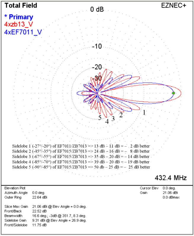
Fig. 5
How to
assemble the EF7011 yagi
In fig. 6 you can see the dimensions of EF7011. All elements are made of
6mm full aluminium. In the center of the element you drill a 2.5mm hole.
After that you take a threader to cut in a 2.5mm M3 screw thread for a M3
screw.
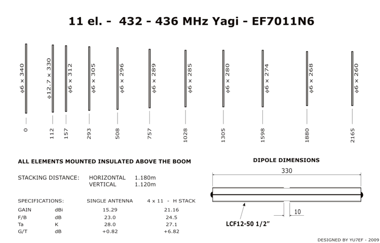
Fig. 6
To fix the
element on the boom I use polyamide holders from Konni antennas.
https://www.konni-antennen.de/einzel-ersatzteile-bausätze
|
Elementhalter-Polyamid |
nur Unterteil 15er oder 20er Boom |
0,95 € |
You can see a 6mm
element on a polyamide holder on fig. 7
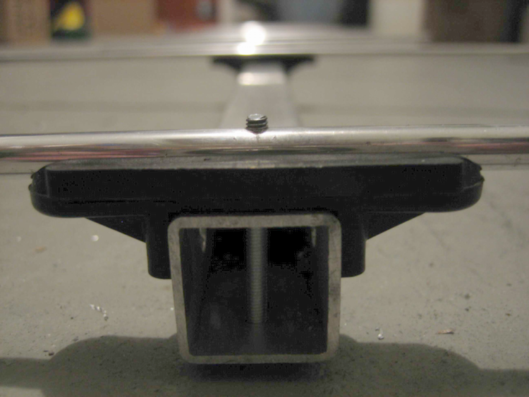
Fig. 7
The dipole is
made of ½ inch cellflex cable like lcf12-50. As you can see in fig. 6 and
fig. 8/9. You only have to cut the coax cable to 330 mm. Then you you
connect the inner and outer line of the coax at every end with a copper
wire and tin-coat the whole area between inner and outer line. Next step
is marking the center of the dipole and cut the outer copper ring at 5mm
to the left and right down to the foam. After that step you will have a
10mm space between left and right side of the dipole (see fig. 6 dipole
down right). After building this dipole into a housing you can directly
connect the needed coax cable to the 4-way power splitter. (See fig. 11).
It is very important, that the coax is running across the reflector to the
power splitter ! (Fig. 10)
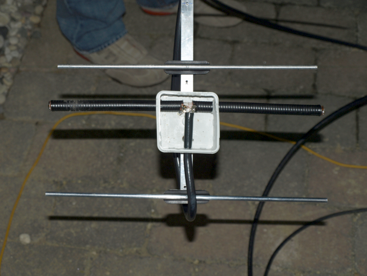 Fig 8 Fig 8
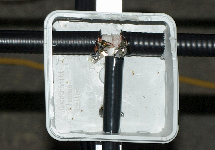
Fig 9
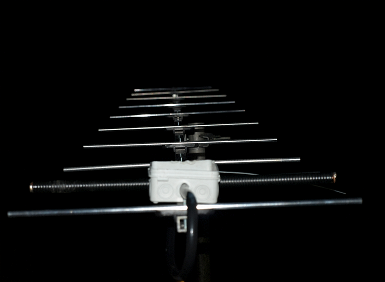
Fig 10
How to reduce
losses between antennas and preamp (LNA, Low Noise Amplifier)
To optimize rx performance, the coax relay should be connected directly to
the power splitter. This is possible by using a male n-connector at the
input of the splitter. (Fig. 11) You should not use coax cable worse than
ecoflex 10 (8.9 dB loss / 100m @ 432 MHz) If you use ecoflex 10 or 15
there is a solderless n-connector available.
When you have assembled the 4 yagis on an h-frame ou should test your rx-performance
by sun noise. Download the software noise meter from G8KBB from the
following link:
http://www.g8kbb.co.uk/NoiseMeter.zip
After installation on your pc and setup of your soundcard click on
“Measure Noise”. (Fig. 12)
Next enable on
the right side of this window “Averaging” and set the number to 10.
Connect the audio out of your trx to your soundcard and set audio level of
your TRX to a low level so that there will be no distortions in the
soundcard ( < -50 dB). After this switch of the AGC of your TRX or if this
isn't possible reduce the RF gain about 10 dB. Use the average reading of
NoiseMeter to reduce gain about 10 dB.
More can be seen
at:
http://www.do9bc.com/dj3jj/rx-performance-table-144-mhz-stations/
+
http://www.ok2kkw.com/next/nl_k2uyh/sun_table_2017.xls
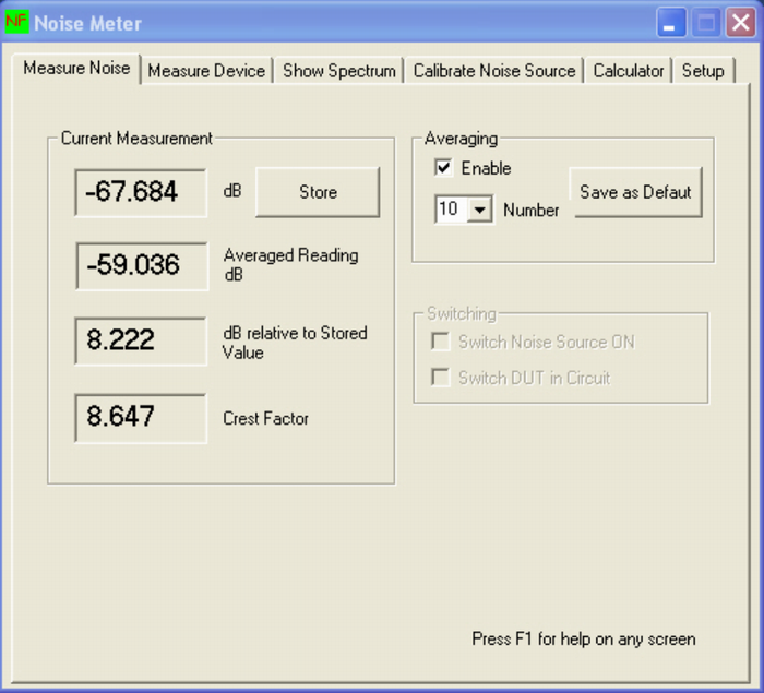
Fig. 11
Now elevate your
antenna > 30 ° into the sky and look for the point with the lowest noise
you can find by looking at Noise Meter. If you have found it press
“Store”. Finally turn antenna into the sun. Antenna looks into the the sun
if you can see an increase in noise on your display. Now press again
“Store” and you can see your sun noise at “dB relative to Stored Value”.
It is very important, that the sun is also > 30° up to be sure not to
measure any noise from the ground. From Fig. 5 you can see that the second
vertical side lobe is at 35 ° so you should have more than 35 ° to
overcome the noise from this side lobe. If the Sun is shining and you have
some warm housetops you will also have an increase in noise if your
antenna is pointing into this direction.
To check the influence of losses in front of your preamp you can try coax
relays with different losses or an adapter cable between splitter and
preamp. With every increase of 0.1 dB loss you will see a reduction
in sun noise of about 0.3 dB !
So the test of your sun noise always gives you a fast answer if your
system is working correctly even if there is no other station available.
You do not need a clear blue sky to measure the sun noise. Not even bigger
clouds will change the measurement significantly.
 2011: Changing QTH to new house,
500m away from the old qth but in same locator JN48js. New Antenna 4 x
YU7EF 7015, 3.4m long with 20.8 dBd gain. Could work first CW random QSO
from new QTH in Dubus EME Contest with UA3PTW on Sunday 10.04.2011 with
549 and O. TX Power 300W.
2011: Changing QTH to new house,
500m away from the old qth but in same locator JN48js. New Antenna 4 x
YU7EF 7015, 3.4m long with 20.8 dBd gain. Could work first CW random QSO
from new QTH in Dubus EME Contest with UA3PTW on Sunday 10.04.2011 with
549 and O. TX Power 300W.
Pse check the
EME logger for contacts and tests: http://hb9q.ch
OK1TEH - TU Andreas for your material & permission to put your material at
OK2KKW web.
|