How to build a 144MHz power splitter
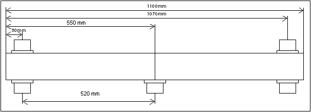
Note: copy from this page, however mistake in lengths were corrected. The right length of lambda / 4 is 520mm.
Power splitters are used to combine 2 or more antennas on 1 feedline. The impedance of each antenna will be transformed to the required impedance at the feed point. The impedance of the transformer can be calculated with the following formula : Z0=Vzout x Zin Where Z0 = impedance of the transformer, Zout = impedance of the feedline and Zin = Impedance of the antennas. For example if you want to combine two 50 ohm antennas using a 1/4 wave power splitter you will have 50:2 = 25 ohm at Zin, the impedance of the transformer will be the square of 50x25 = 35.35 ohm. If you want to use a 1/2 wave power splitter you will need 100 ohm from each antenna at the feed point to get 50 ohm when you put them together. To get this 100 ohm you will need a transformer with the following impedance : Z0 = square of 100 x 50 = 70.71 ohm. Below there is a drawing of how to construct a 1/2 wave power splitter for 144MHz.

This drawing is not to scale and all dimensions are for 144MHz. The outer tube is a 30x30mm aluminum square tube 2mm thick. This gives an inner diameter of 26x26mm. The impedance of the transformer depends on the ratio between the inside diameter of the outer conductor (D) and the outer diameter of the inner conductor (d). Below is a table of often used impedance's and corresponding D/d values. The first colom is the number of antennas you want to transform to 1 feed line. For example 4:1 means that you use 4 antennas each 50ohm and you want to transform the total impedance on the feed point back to 50ohm. This can be done by a 1/4 wave splitter with the feedpoint at the bottom side and 4 connectors at the top or a 1/2 wave splitter with the feed point at the center and 2 connectors on each side (1/4 wave) from the feed point. One important last note is that the inner conductor has to have a length of 530mm for a 1/4 wave and 1050mm for a 1/2 wave splitter. This inner conductor has to be exactly in the center of the square outer conductor to be sure of the right impedance. For inner conductor I used copper water pipe from the plumber. This water pipe is available in different diameters and rather cheap. For connecting the N-Chassis to the pipe I used 2mm silver plated copper wire. (I will add some detailed photo's to this page in future)
| Number of | 1/4 wave | 1/4 wave | 1/4 wave | 1/4 wave | 1/2 wave | 1/2 wave | 1/2 wave | 1/2 wave |
|---|---|---|---|---|---|---|---|---|
| Antennas | Z ohm | D/d | D/d | D/d | Z ohm | D/d | D/d | D/d |
| 2:1 | 35.4 | 1.67 | 26/15mm | 31/18mm | 70.7 | 2.98 | 26/9mm | 31/10mm |
| 3:1 | 28.9 | 1.50 | 26/17mm | 31/21mm | ||||
| 4:1 | 25 | 1.40 | 26/18mm | 31/22mm | 50 | 2.13 | 26/12mm | 31/15mm |
| 6:1 | 40.8 | 1.83 | 26/14mm | 31/17mm | ||||
| 8:1 | 35.4 | 1.67 | 26/15mm | 31/18mm |