|
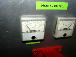
Voltage regulator for G1--
CZ --
EN
Voltage regulator for G2--
CZ --
EN
"Long life" 144 MHz, 750+ Watt PA
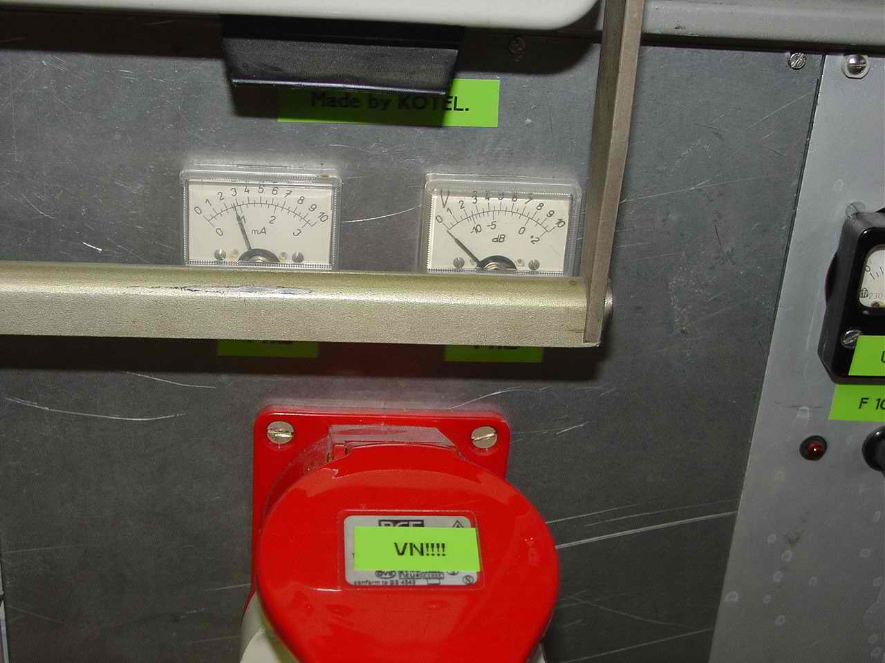
MADE BY KOTEL
With GU78B tube....
As our club is very active in VHF/UHF contests there has always been a
need of a reliable high-power PA for 2m band. Although the current power
limit in OK is just 750 W, we decided to construct a brand new PA with a
big margin of power which would last "forever" and can be possibly used
for EME as well. Since 2 pieces of GU78B were lying for longer time on the
shelf in my ham shack I chose this tube. It's a tetrode designed for
linear PAs with sufficient power dissipation. Besides I was able to get a
socket for it on flea market at reasonable price. Also driving such a tube
to just a little part of its potential power ensures a clean signal in
comparison to smaller tubes driven to their maximum. This is very
important in big VHF contests with high number of stations in a small area
(a very frequent case in OK).
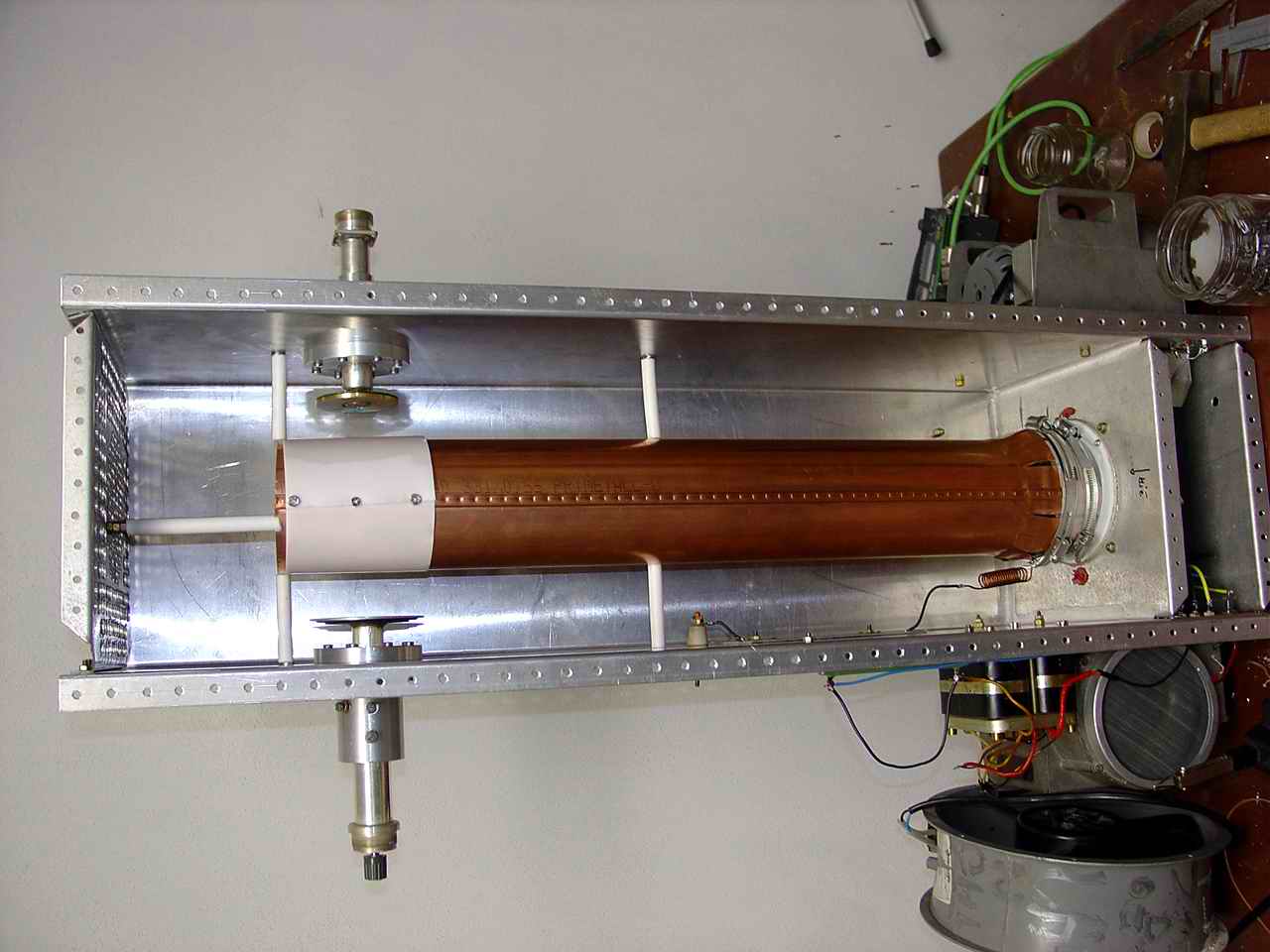
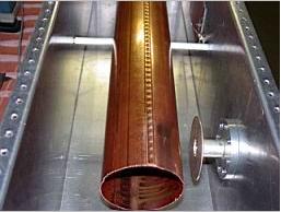
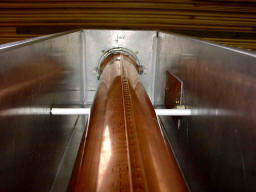
For fundamental construction problems at high power level (especially the
anode isolation capacity) I droped the usual lambda/4 design and developed
a construction with the lambda/2 resonator. Of course there's a big minus
in its dimensions, not only due to total cavity length of almost 1m, but
also due to the high voltage (about 105kV) at the end of the resonator.
However, there are some important advantages in this construction. No
anode isolation construction capacitor, small tuning and coupling
capacities and the last but not least the long and massive copper pipe
improves the temperature stability of the tube. The higher intended power
the bigger significance of these advantages. From certain power level the
classic lamda/4 design is not feasible.
Note: PA is not for sale !!!
Technical parameters:
Ua - 3100v - no load.
Ua - 2500v - at full load.
Ug2 - 315 V
Ia - 1.5 A
Ia PEP - 4A
I fil - 3.5 - 4A
U fil - 27V
U fil - EME - 28V
P out - 3000W linear (intended)
P out MAX - 4000W peak maximum to limitation
http://www5a.biglobe.ne.jp/~jh2clv/ - GU84-6m
More pics on N2DX web page.
And remind: Life is too short for QRP!!!
--------------------------------------------------------------
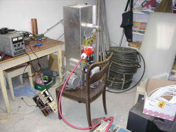
Practical tests and construction process.
4.4.04
OK1VPZ promised a big cooling turbo fan. It means that old military
blowers can be dismounted and some changes will be
done at the rack and air vents for better cooling.
28.3.04
PA tested under load 900W in 500W out. Except of small matching problems
in cathode circuit all OK.
25.2.04
There's no appropriate material for the rack at the moment. As soon as I
have some the work can continue.
15.2.04
Tests of g2 protection and g2 power supply. Test OK - switch on at 2100 V
of anode voltage, off at 1000V.
7.2.04
.Added a choke for protection of the output relay, the auxiliary
transformer and the plate with regulated power supply for g2.
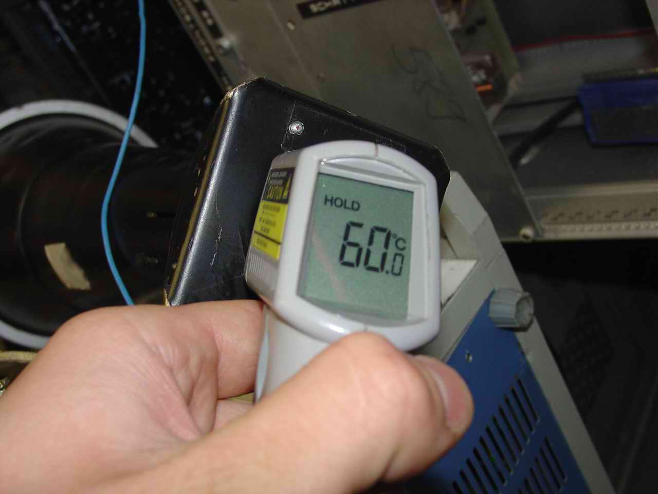
5.2.04
Temperature test. 1250 W DC-dissipation for 5 minutes. The temperature of
outgoining air was about 60 degrees centigrade (not very precise
measuring), but it's OK for the sufficient cooling. Estimated temperature
at the tube was about 130 degrees.
---------------------------------------------------------------------------------------------------------------------------------------
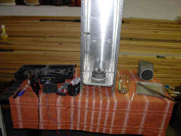
Completed ready for TX
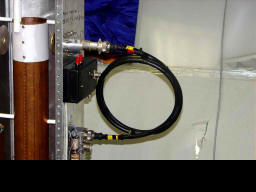
Coax relay for RX/TX switch ...
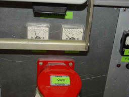
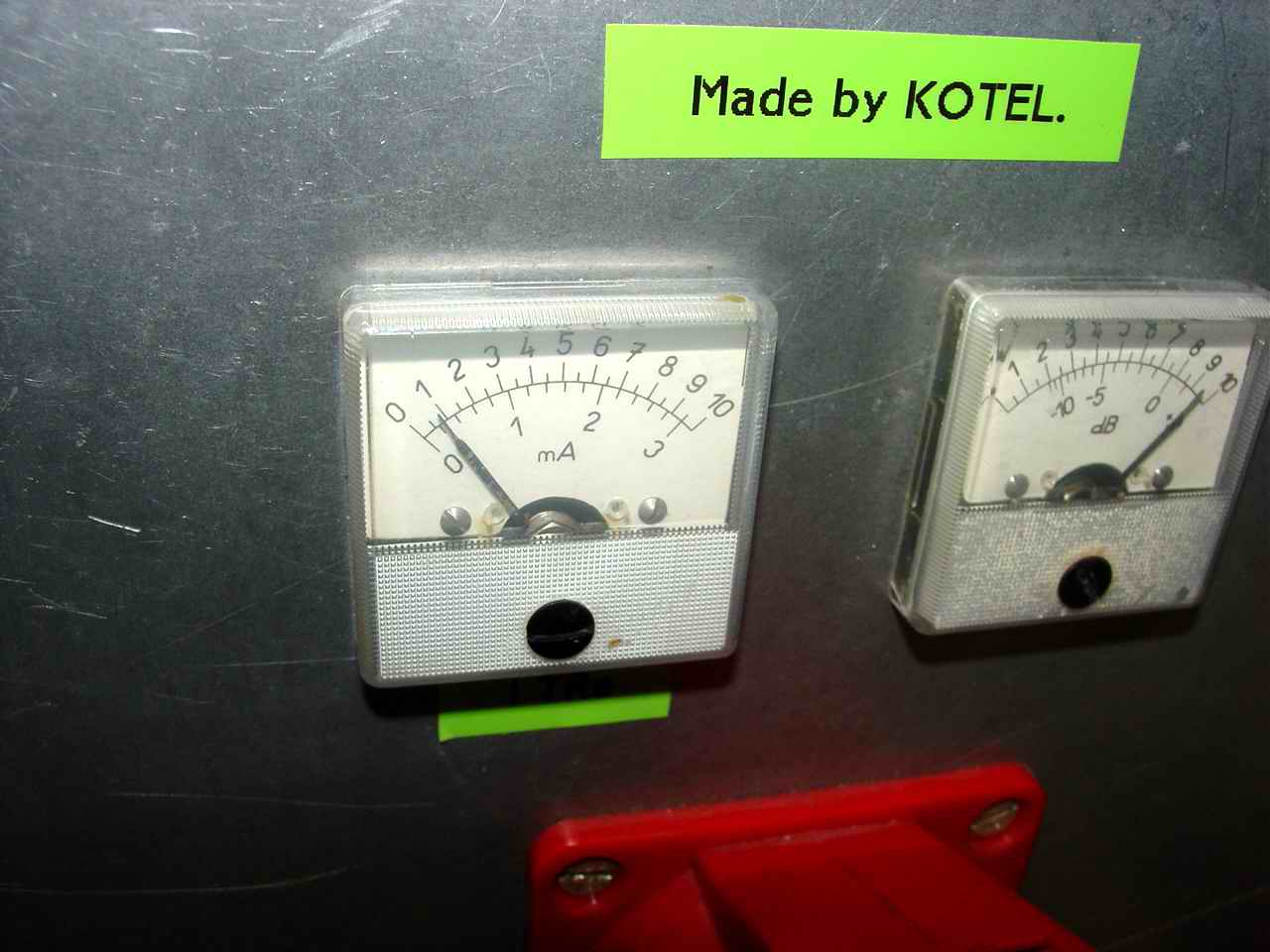
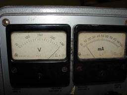
Anode current abt. 300mA of 3kV --- 900W IN

Temp of big dummy load in 3rd minute
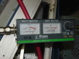
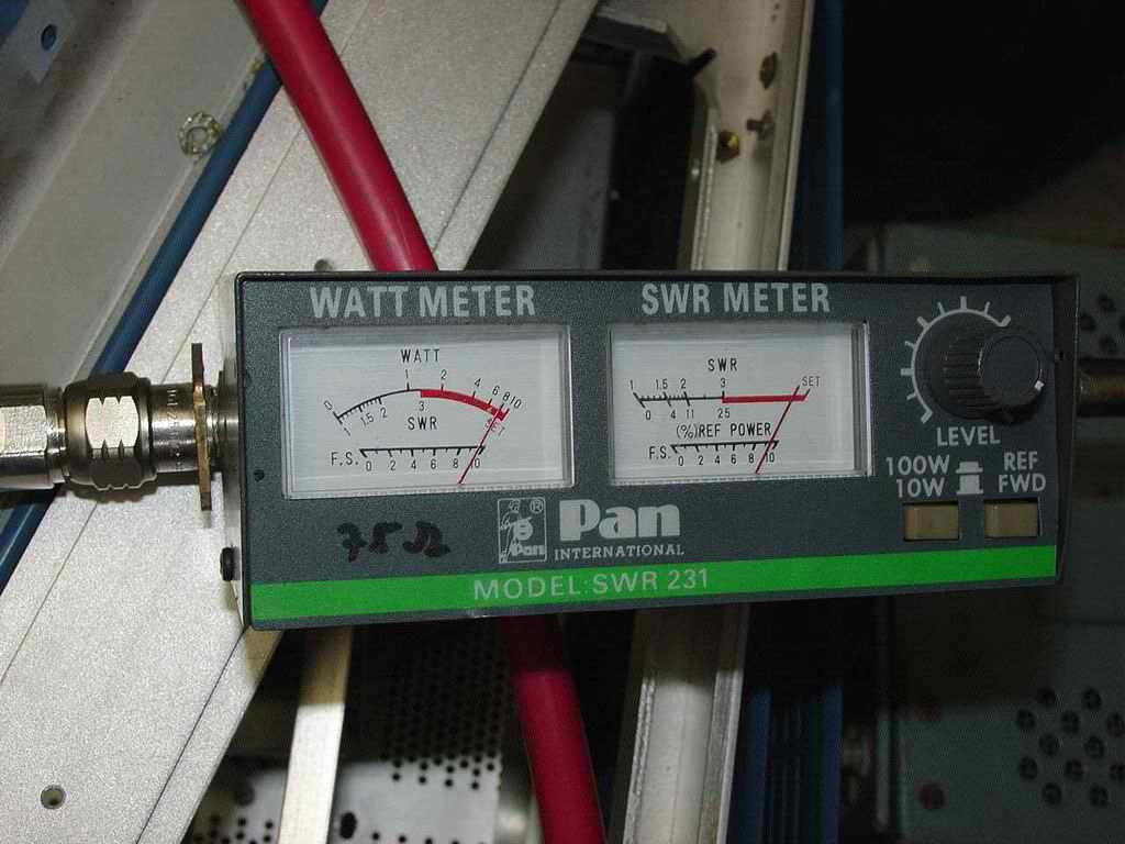
Output PWR. This meter is up to 600W only ...
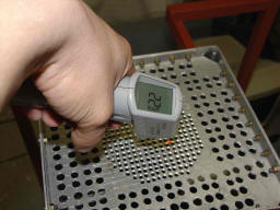
Cooling air temp 400W out after 3min. Room temp 15°C
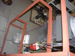
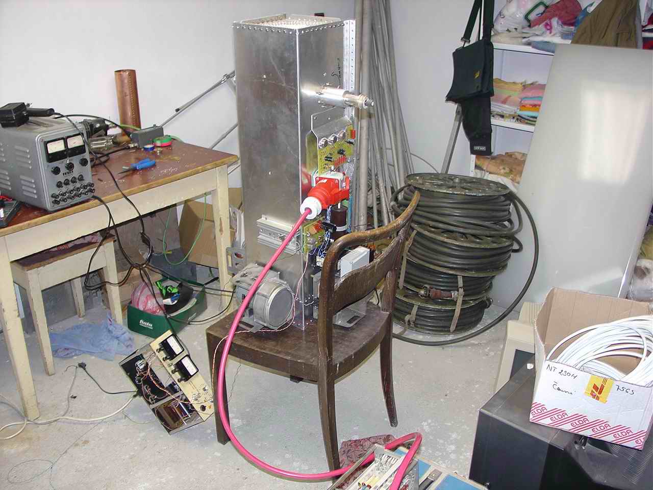
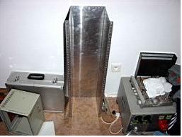
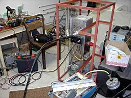
Frame structure is a bit large ...
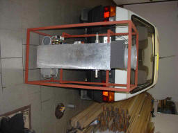
Completed for transport ...
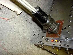
Cathode connection
HV PS
After a slap in tube :-) R-1Ohm 5W
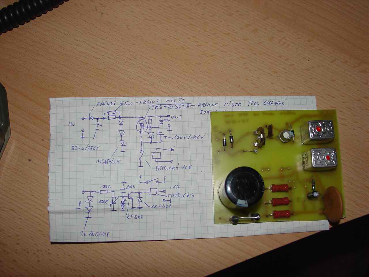
Schema. Unfortunately not in full resolution....
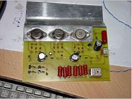
Note .. g1 and g2 power supply are connected as usual parallel
stabilizers. G2 protection observe high voltage on anode, if there is at
least 1kV potential. If not, the G2 is switched to zero to protect a tube.
The next protection is watching of SWR....
Test of g2 protection .. switch ON by 2100V and switch OFF by 1000V.
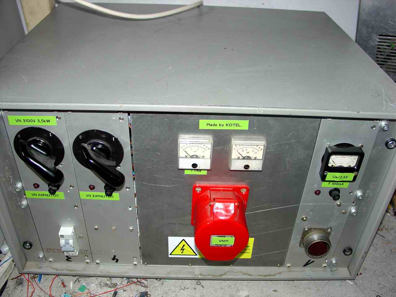
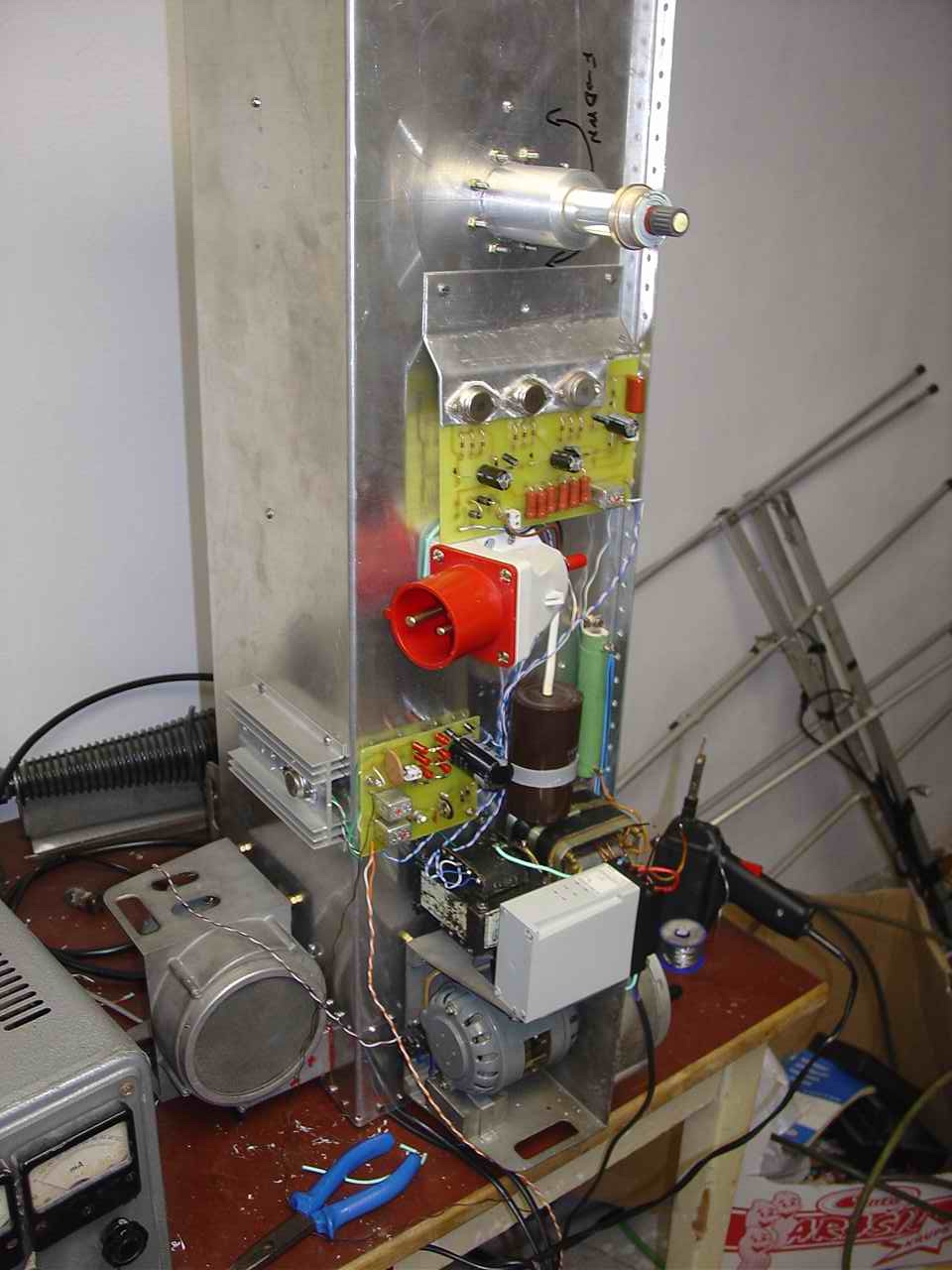
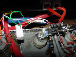
Important circuit, when High voltage on anode is OFF!!!
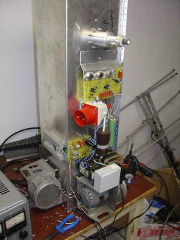
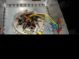
From top to down: G2 PS, HV socket, G1 PS, transformer and van.
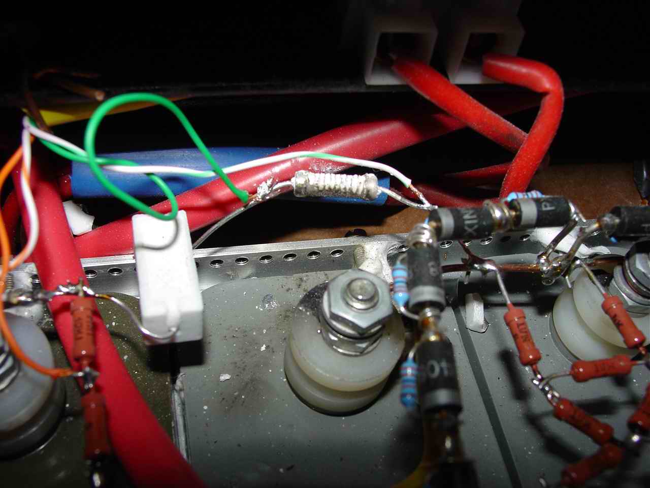
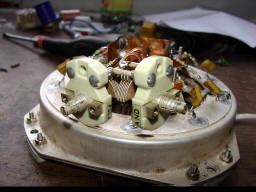
Some of important parts pic...
On right side choke of antenna galvanic connection protection. It protect
coax. relay. If the output is not connected, the G1 PS is blocked.
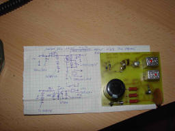
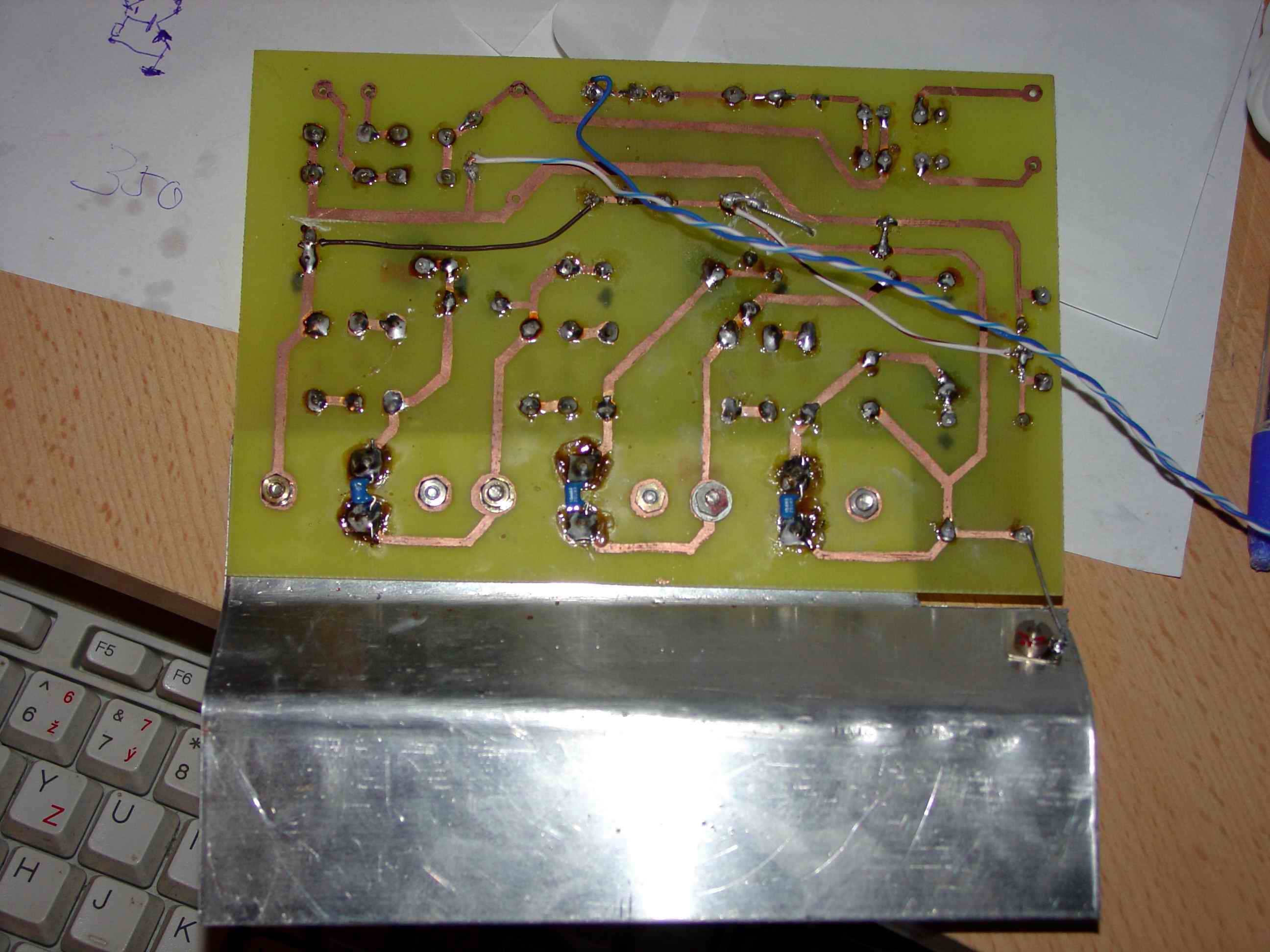
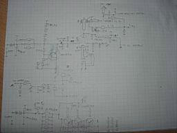
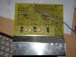
G1 PS and G2 protection schema. I made it in school during Czech lesson,
hi... On anode voltage is divider 1 by 1000 and if the HV is more, than
1,5kV, the G2 PS switch ON. It is very important! If the G2 potential is
higher, than anode, all electrons, emited by cathode are impacting to G2
and because such G2 grid is not designed for major load, burn out and the
tube is destroyed!!!
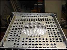
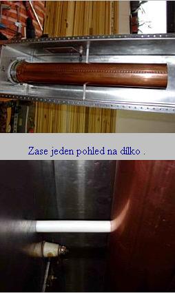
Ventilation cover MK III. :-)
Mechanical assembly
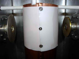
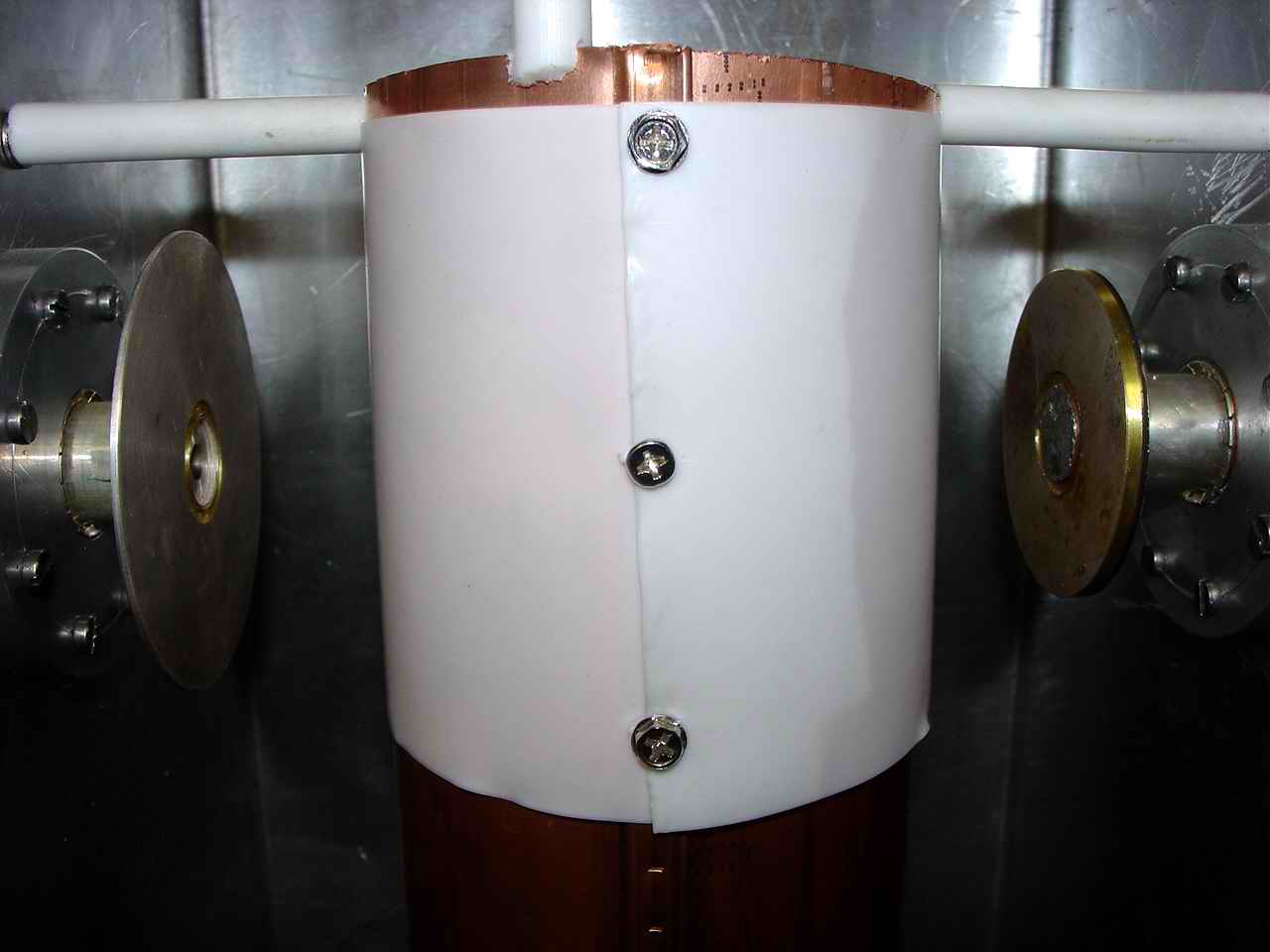
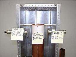
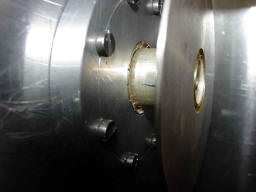
End of resonator. The white material is a teflon. On left tune on right
coupling disc.
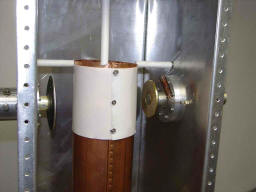
Coupling adjustment..
Tune disc ...
Anode choke and 2nd. version of ventilation cover

Vacuum improvement !!!
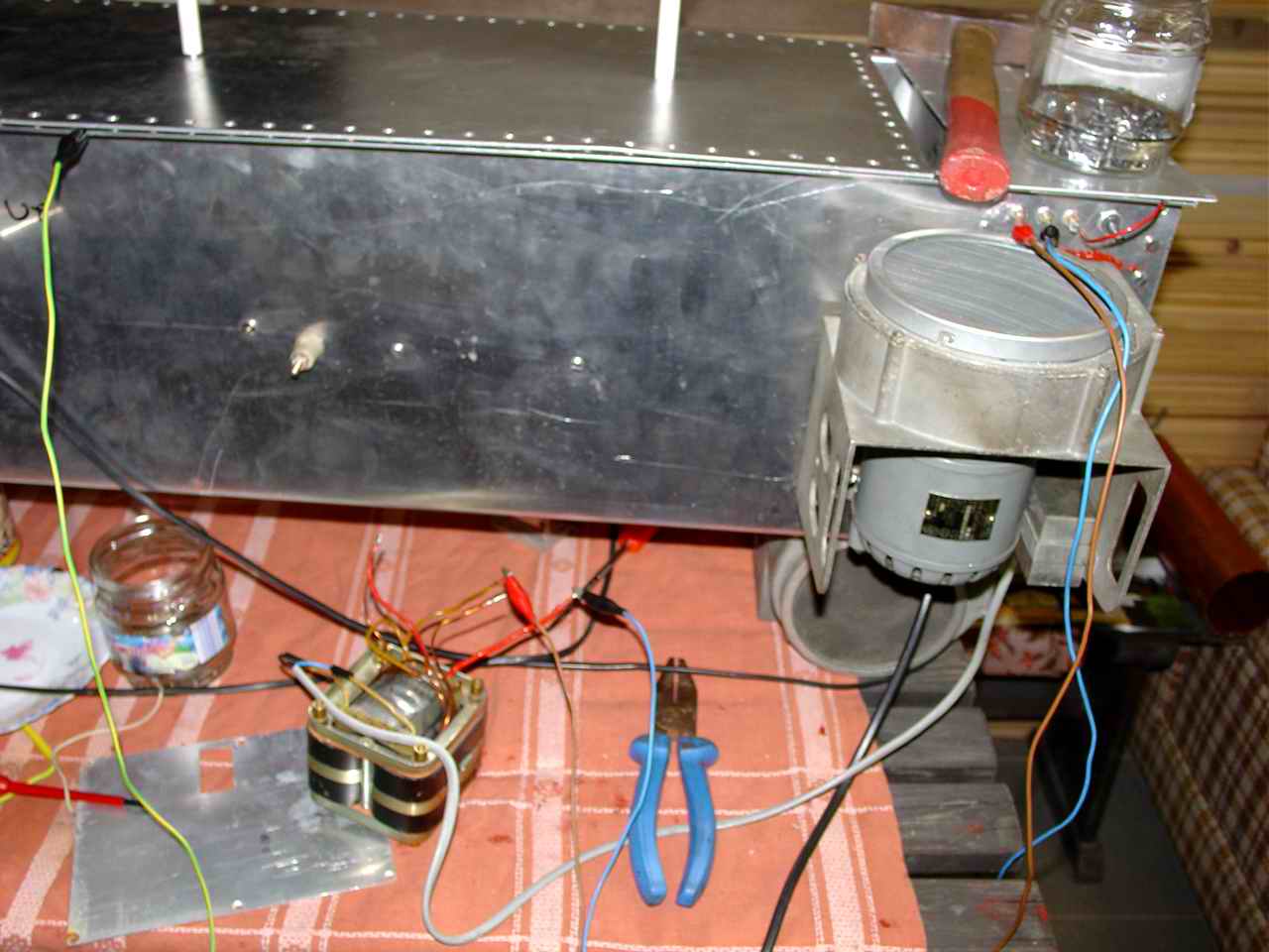
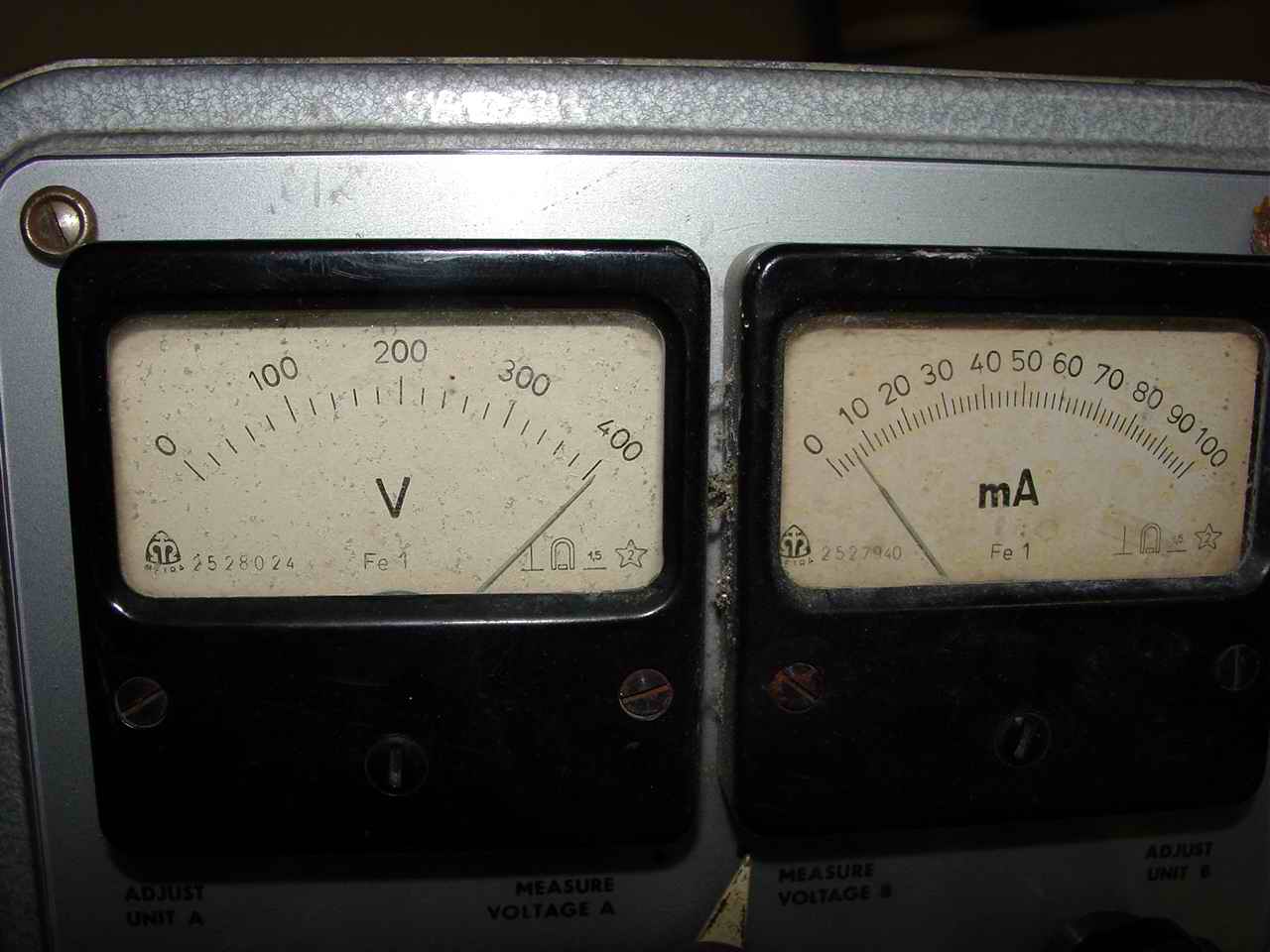
My well proven PS - laboratory supply TESLA 2x400V. Just used in proces of
GU78b vacuum improvement... Ua - 800V , Ia - 6mA , Uf - 28v , If - 4A
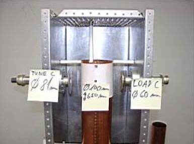
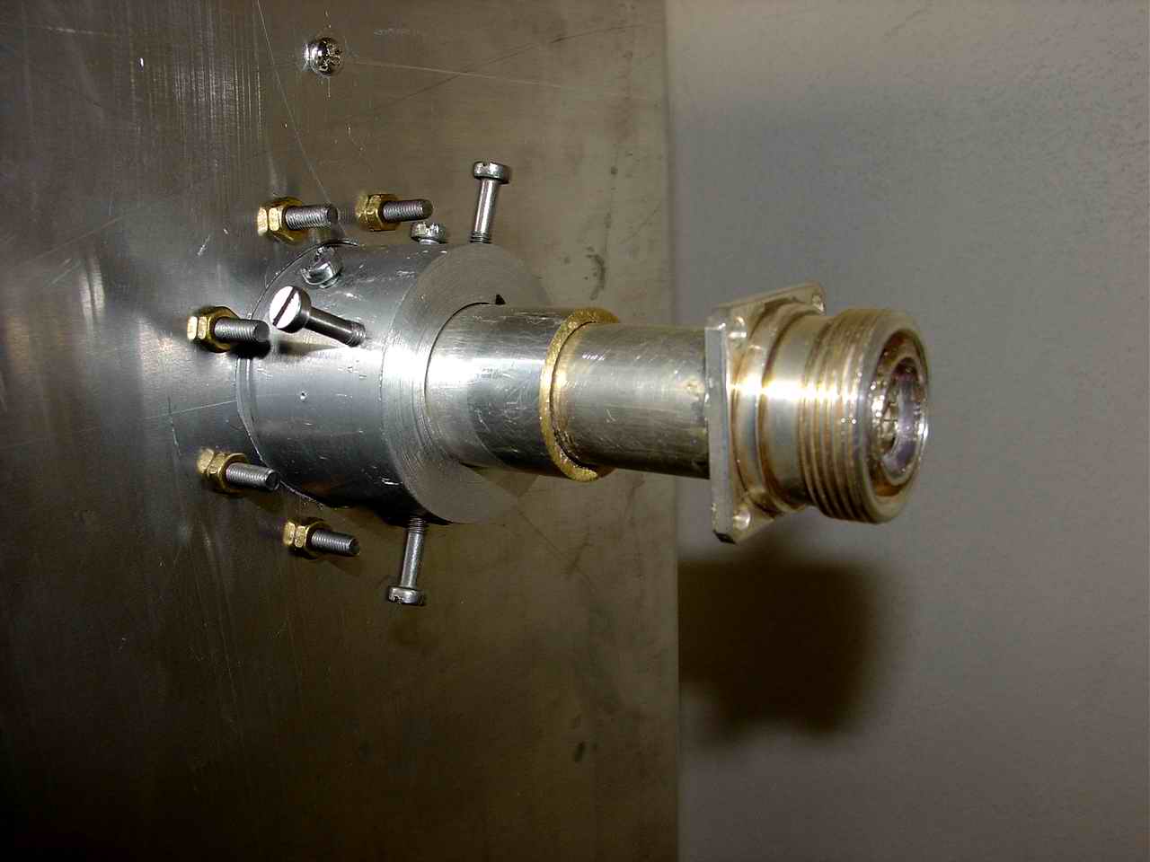
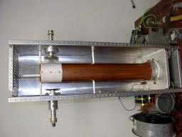
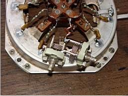
Detail of tuning system. Some parts were used from old military equipment
duplexer RDM 6/12
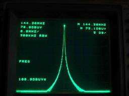
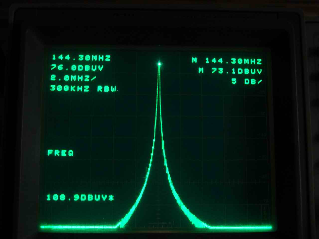
Well done: Q of unloaded resonator. Qn >> 700.
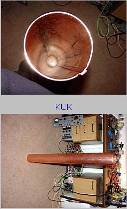
The very first RF measure... where is the resonance... resonator is a bit
long.... handsaw helps...
when the resonator pipe was cut by few cm, the 65cm lenght has
considered as the right one....
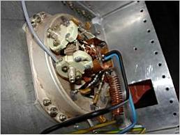
Socket connection.
Long way home :-)
Resonator pipe holders

HV connection and capacity from PCB plate

Not very nice, but it works!
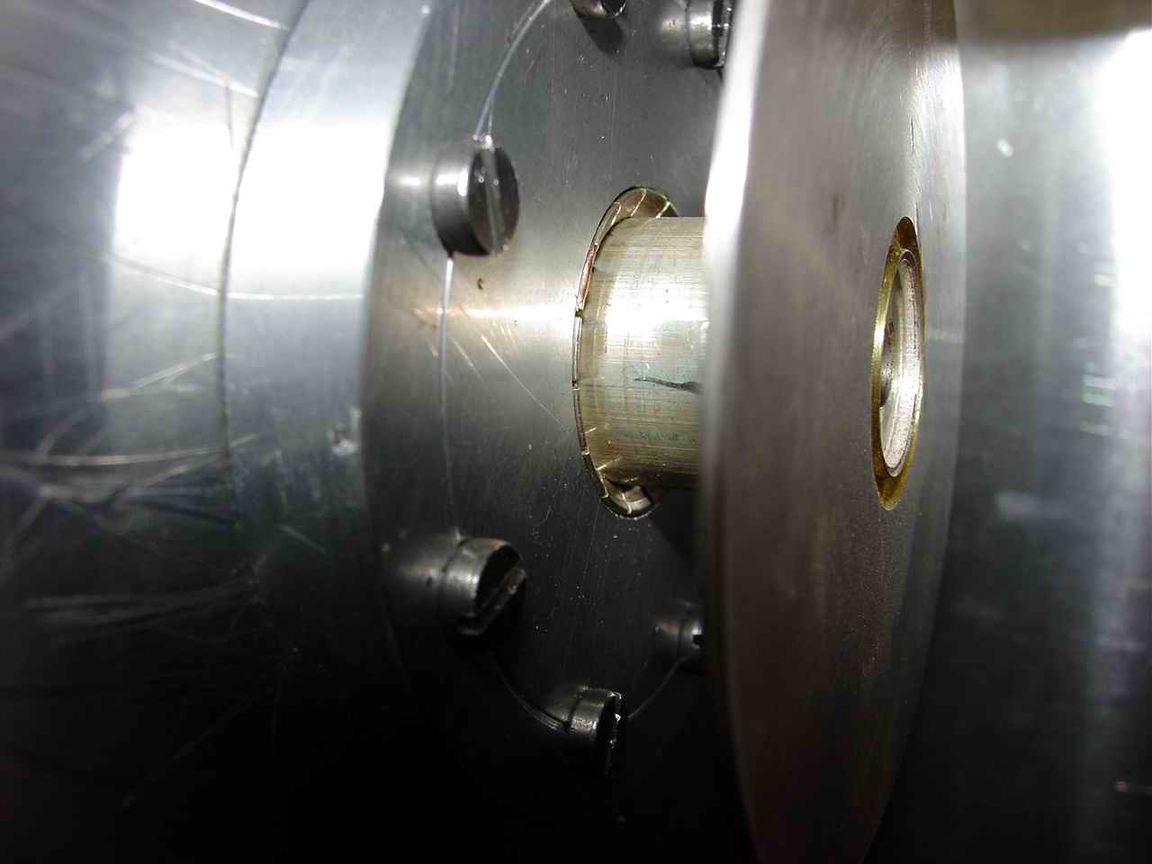
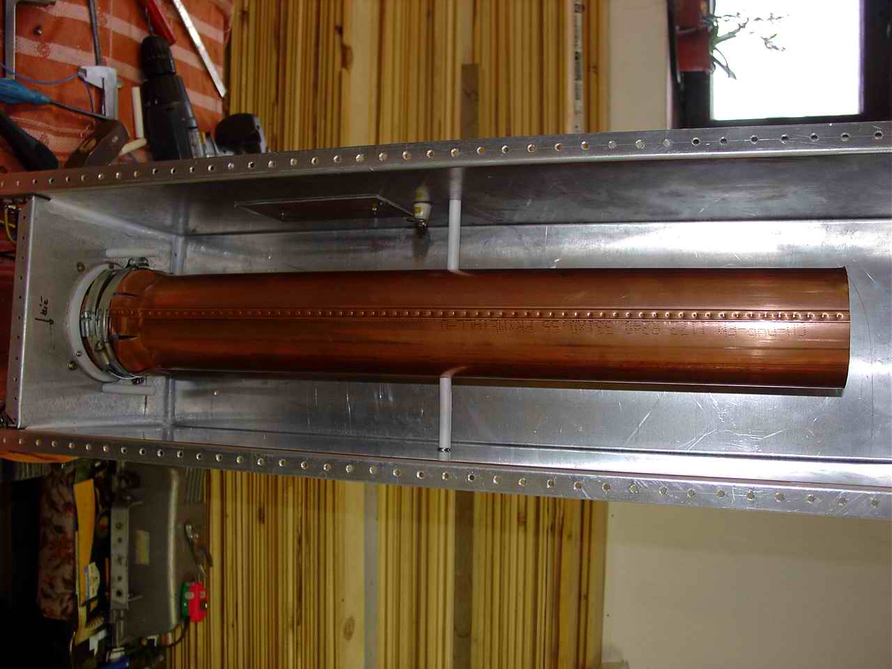
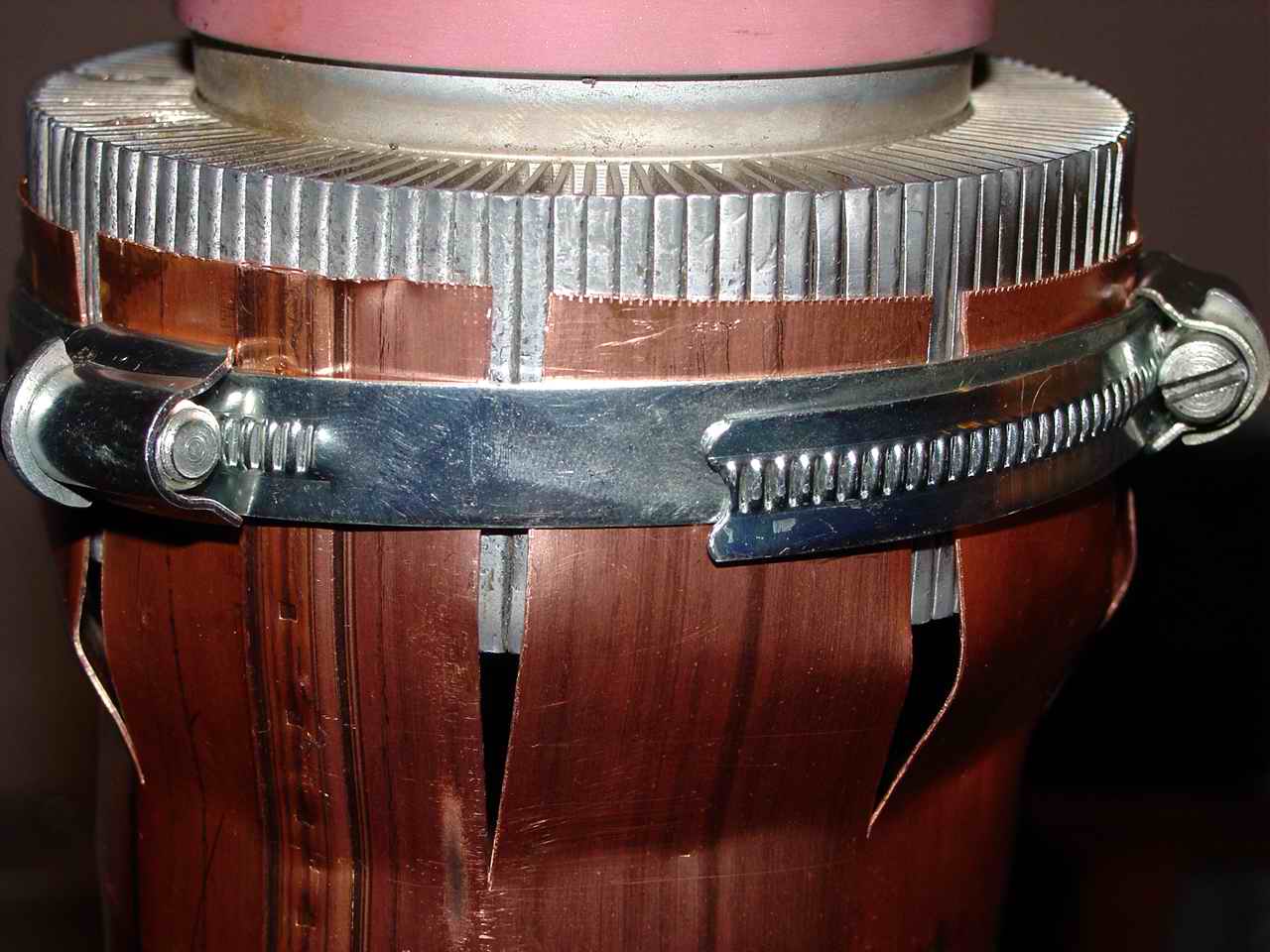
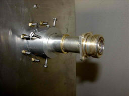
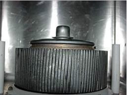
Connection of GU78b and a resonator pipe.
How to match the copper pipe 100mm to the tube heatsink with 110mm dia?
That's the question!
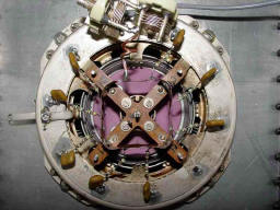
Tube socket bottom view with matching resistors and a LC circuit
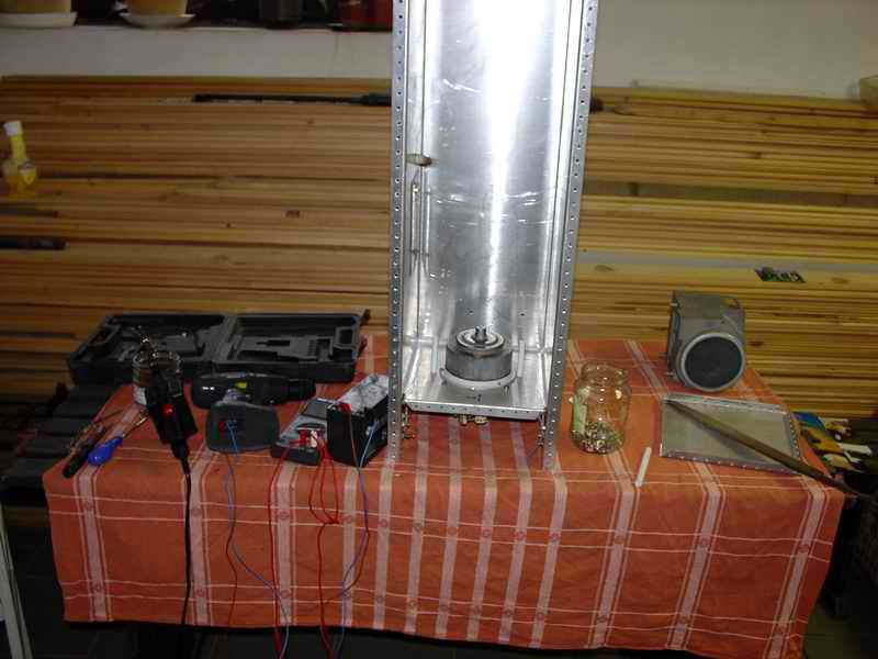
First tube insertion into a cavity
tube in a socket
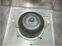
teflon legs were finaly not used
socket assembly
LC match
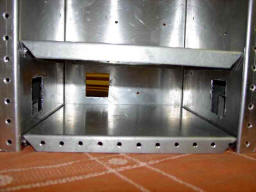
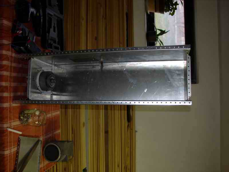
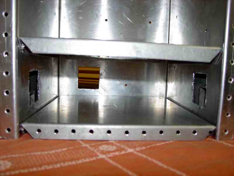
cavity bulkhead for socket

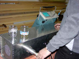
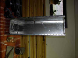
tinsmith job
the cavity construction is in
total 900mm long
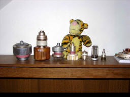
Collection: from
left GU78b , GS35b , GU74b , GI7b , RE025XA (4CX250) , GU50 , HT323
(2C39BA)
G2 stabilizer is a basic condition
for PA with tetrode...
G2 PS is fundamental for such PA .. it must be designed as parallel
stabilizer! If not, some electrons are returning from anode and it
increase potential on G2 until the tube take a spark... and if the voltage
on G2 is not stable, it change the gain and the PA produce splatters. And
even it may destroy the tube at all!
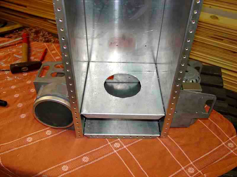
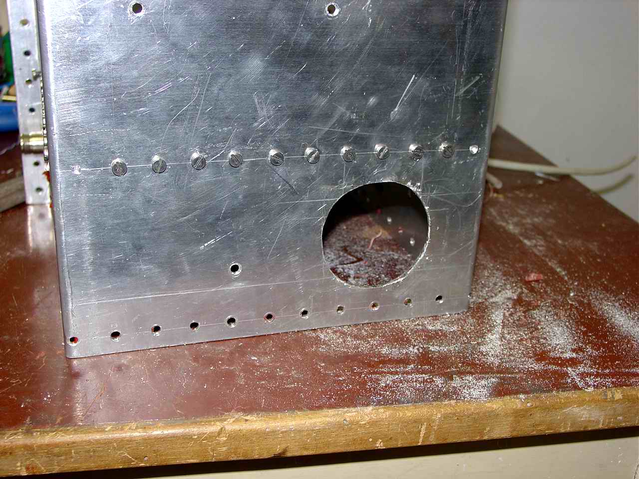
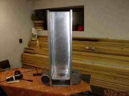
On the very beginning. It has started with aluminium plate 1000x1000mm,
2mm thickness, used for cavity production..
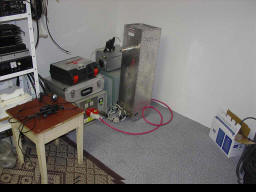
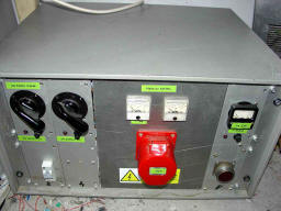
Size: 900mm high , 224mm wide , 232mm deep. On right is a prepared
PS for PA: 3100V DC 4.5kW input
Last update of this page content :12.4.2004 12.50
--------------------------------------------------------------
More:
http://www.nd2x.net/OK1BAF.html
Bias
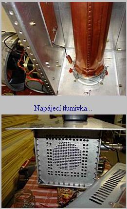
Filament and PTT connection into cavity

Input of the cooling air from the big blower ..
Socket with added attenuator resistance 125Ohm .
Last pic of testing before cooling improvement
|