|
Dutch version here.
The Icom IC9700 is a nice radio with many great
features.
1. An essentially flat passband from 100 Hz to 3000 Hz
that is a useful advantage for wide bandwidth digital modes such as
MSK144, ISCAT-B and QRA64-E.
But the IC9700 drift a lot and does not really lock on
the 10 MHz. REF input. This REF input is used like an old fashioned XTAL
calibrator, the way we did in the old days with tube receivers. Most of the hams needing ultra-stabile equipment have a 10 MHz house reference alraedy. Often a GPSDO with 10 MHz output. So do I. And I don’t want an extra GPS antenna nor receiver. Time to look for another solution. Leo Bodnar in the UK sell injection boards on his web shop. When one feed a 49.152 MHz. reference signal into this board the IC9700 will lock on it. Have a look on the picture here.
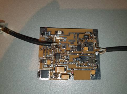
There is a fine description on the Leo Bodnar web site: www.leobodnar.com/shop/index.php?main_page=product_info&cPath=107&products_id=352 Dieter DF9NP made me some nice PLL oscillators in the past for GHZ equipment. I contacted him and described my demand for the IC9700. And he confirmed he can make me a 49.152 MHz PLL locked on a 10 MHz reference. Soon the prototype was tested and worked very well with 15 dBm output. Have a look on the picture of the board here..
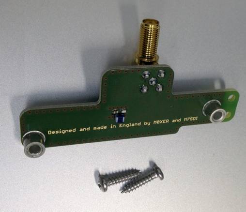
Together with the Leo Bodnar
injection board it will be possible to lock the IC9700 on the 10 MHz
reference. This is a cheap solution. All together around €90.- depending
on shipping costs. Using the board it also means that one need a 10 MHz reference. Without the 10 MHz reference the rig will not operate correct because the PLL will generate noise and spikes. If one will use the IC9700 without the 10 MHz reference the 12 Volt supply need to be switched off the board. You may also decide to use the PLL board outside the IC9700 and use the REF input SMA on the IC9700 for the 49,152 MHz signal that will be supplied direct to the injection board. Without the external 49 MHz reference the rig will work on its own internal (drifting) oscillator. All tests confirmed the stability is within 0,1 Hz with the new PLL on it. A great step forward making the IC9700 a world class radio. It can be used for all demanding digital modes like JT65 for moonbounce.
Installing both boards in the IC9700 is easy.
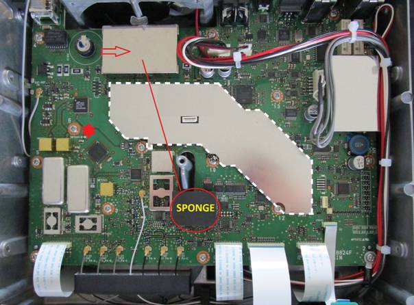
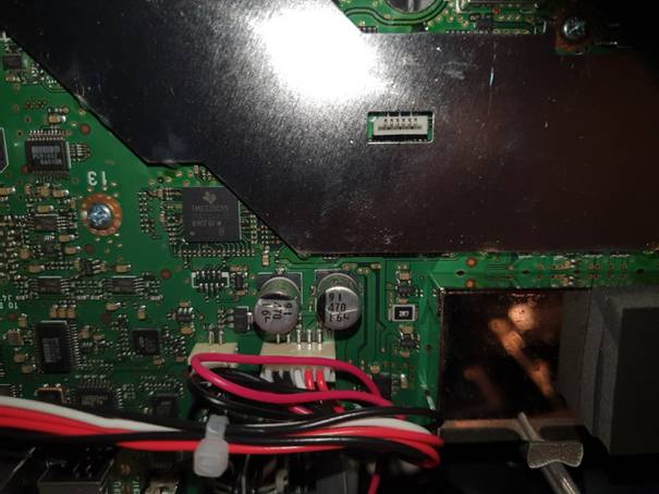
Now put that black airflow protection sponge to the place market with the arrow on the picture here below. That will be the place for the PLL board.
Also notice the red star on the picture. This will become the DC ground point for the PLL board.
New position for the “sponge”
Put a piece of good quality
double-sided tape on the sponge which is on the new place just beside the
battery. Now put the PLL board on top of the sponge, it will kept in
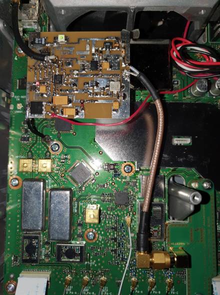
position with the tape. Now prepare the coax with the SMA socket (female)
and mount it on the board and the back side of the IC9700. Make another
coax with a SMA male, solder it on the board and connect it on the
injection board. I used pieces I had in the junk box. It is not critical
but make it as short as possible. Have a look on the picture here below.
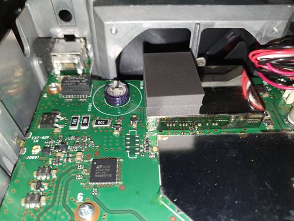
The PLL board need 12 Volt supply. The main board get it on the white plastic connector from the power distribution inside the rig. I soldered a thin red wire on the paths just near the white connector. This is the 12 Volt connection. It correspond with the two red wires on the connector. If you don’t want to solder on the board you might prepare on of the two red wires to take 12 Volt from there. Have a look on the photo here.
Now you need to create a DC ground for the PLL. I used a lip that I put underneath the screw marked with the red star on the first picture. Use a thick wire for this, it will also act as a extra support for the PLL board and keeps it on the sponge.
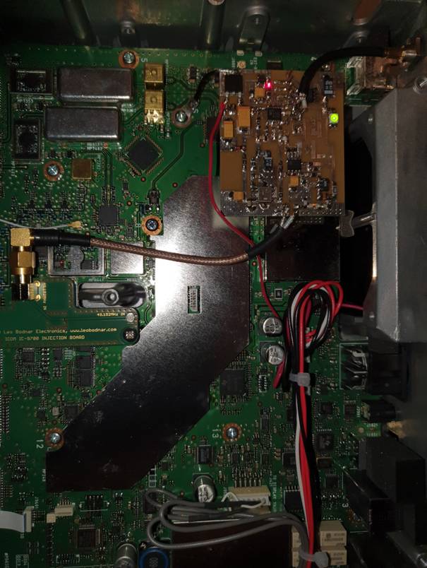
Fully functional PLL board in the IC9700
Now your IC9700 is ready and you can switch it on. Do not close the rig yet, You need to see the two LED’s on the PLL board. When you switch it on the green LED will go on.No connecta good 10 MHz reference to the back of the IC9700 on the SMA called REF. As soon the 10 MHz reference is connected the red LED will go on and showing the PLL is locked. If none of the LED’s will go on check if there is 12 Volt on the board. With the board working well now you need to setup the IC9700. If you had the rig working on a 10 MHz reference it will give an error message telling that it is missing the 10 MHz. Just confirm that and go on. It will not show up anymore.
Now put back the enclosure and all screws. It is all done and now you have a reliable state of the art transceiver. Good luck with it and see you of the moon. 73, Peter Gouweleeuw PA2V References: DF9NP
MiniKits VK1XX
|