 S11=0; S22=0; S31=1/(1+a)
 Power Dividers and Combiners
Copy from the web page: http://www.bibel-reflektion.de/html/circuits_and_components.html
Power dividing and combining is a standard requirement for RF- Designers. The following circuits or components are used :
1.0 The Wheatstone Bridge as a coupler.
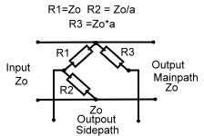
The easiest way to couple a signal in the range from DC to 500 MHz into an other path, is the use of a Wheatstone bridge. The advantage of this circuit is: He is only resistive, has no transformer no complex wiring and is ideal for digital broadband application. But the outputs have no reference to ground. Fig.1 Therefore this bridge is seldom used. At lower frequencies , the 2 outputs can drive a RF-Operational Amplifier . Fig1 shows a circuit and its resistance values depending on the coupling factor a.
S11=0; S22=0; S31=1/(1+a)
Fig.1 Wheatstone Bridge used as coupler
2.0 Wave Line and Twisted Wire Wave Line Combiners
Twisted wire wave line combiners and dividers are realized using a
combination of broadband
 wave
line transformers. Due of the used technique they are restricted to relatively
low frequencies, but they have the advantage to be very broad banded and very
small in size. It is therefore sometimes desirable to realize such a combiner
for high frequencies up to 1 GHz. This becomes clear, if one compares the size
of an 3 dB strip line coupler having a dimension at 1 GHz of 7*7 cm, with the
0.5 cm square of a twisted wire combiner.
wave
line transformers. Due of the used technique they are restricted to relatively
low frequencies, but they have the advantage to be very broad banded and very
small in size. It is therefore sometimes desirable to realize such a combiner
for high frequencies up to 1 GHz. This becomes clear, if one compares the size
of an 3 dB strip line coupler having a dimension at 1 GHz of 7*7 cm, with the
0.5 cm square of a twisted wire combiner.
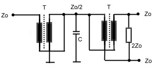
Fig.1 Twisted wire wave line transformer divider/combiner
A standard twisted wire wave line combiner is shown at Fig1. Two equal wave line transformers are connected in series. The input transformer matches the power dividing output transformer. This arrangement may be used as combiner or divider. The capacitor compensates the stray inductance’s at broadband applications. This circuit obviously is a three port. Using a simple 1:1 normal transformer realizes a four port device, Fig.2. Here, the transformer will limit the bandwith. A better RF- solution is it, to connect wave lines or twisted wire wave lines in a series- parallel circuitry, Fig.3 .The wave lines at Fig.3 may be replaced by twisted wire transformers, but if the Impedance of the twisted wire is not equal to Zo, phase deviations up to 25 degree will occur. There are many possibilities to build wave line combiners and dividers in a similar manner.
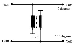
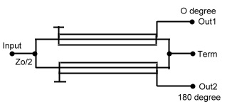
Fig.2 Simple 4 port coupler Fig.3 Paralleled Wave line coupler
One classical circuit at low frequencies is the Sontheimer coupler
US Patent 3426298 of 1969. Fig.2
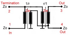
Fig.2 Sontheimer Coupler
Practical Data’s of Twisted Wire and Wave Line combiners are:
Further readings wave line combiners :
R.E.Fisher, “ Broadband Twisted Wire Quadrature Hybrid, “ IEEE Transaction on Microwave Theory and Techniques.” Vol. MTT-21, May 1973
3.0 Line Hybrids
Hybrids in general are 90 degree combiner or quadrature couplers Fig.1 One of
the two outputs has a phase difference of 90 degree referred to the input port.
The fourth port is the isolated port, which must be terminated, but has normally
no power on it. Line hybrids are such 90 degree combiners and are very popular
at frequencies in the UHF range.They divide the input power at port 1 to two
output ports 2 and 4, having a loss of >3dB. Therefore they are called “ 3 dB
couplers”. The two outputs have a phase shift of 90 degree. Port 3 must be
terminated, to absorb reflected power in case of output mismatching; normally
there is no power at this port.The input port matching therefore is relatively
independed of the output matching.The mechanical construction is very simple.Two
lambda/4 lines are coupled by means of a very good delectrica either in a cable
or on a substrate.The mechanical length can be shortened if the lines are
meander shaped The dimension of the coupler depends on the epsilon of the
dielectric medium.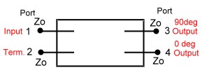 In this hybrid, we have two impedance’s, the mutual impedance between the two
lines Zm and the impedance’s from the lines to ground Zg. The coupler input
impedance then is :
In this hybrid, we have two impedance’s, the mutual impedance between the two
lines Zm and the impedance’s from the lines to ground Zg. The coupler input
impedance then is :
Zo = SQR(Zg Zm).Fig.2
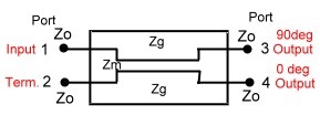
Fig1. Basic Hybrid ^ Fig.2 Line Hybrid
Practical Data’s of Line Hybrids are:
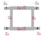
4.0 Brunch Line and Ring Couplers
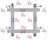
Brunch line couplers are Hybrid couplers related to Fig.1 of 3.0 They have four lambda/4 branches , and are the classical microwave couplers. They are very easy to realize as PCB or micro strip on a substrate. But they have the disatvandiges of low bandwidth, 90 degree phase between the two outputs, a loss of >= 3 dB and big dimensions at frequencies below 1 GHz. Fig.3 presents the mechanical drawing of the classical brunch coupler. Each branch has a length of lamdba/4 .Besides this arrangement other mechanical outlets are possible. If the input and output impedance’s are different , the brunch impedance will be:
Zo = SQR(Zin Zout /2): Fig.2 shows a brunch coupler version having Lamba/8 matching stubs on the inputs .
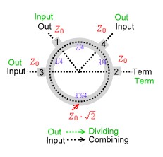
A similar microwave coupler is the ring (or magic T coupler, this is a waveguide structure) and is shown at Fig.5. This hybrid may be used as combiner or divider if the inputs and outputs are exchanged. (green = divider, black is combiner.) The phase difference of the output is -180degree.
The hybrid transmission is a function of amplitude ratio and phase of the incoming signal.Therefore, to combine signals with an hybrid, they must be matched within a certain percentage in amplitude and phase.
Fig.1 Brunch line Coupler Fig.2 Matched Brunch line Coupler Fig.3 Ring Coupler (Magic T Hybrid )
Practical Data’s of brunch line and ring couplers are:
5.0 Wilkinson Couplers
Wilkinson couplers or hybrids, are n- port couplers what means, signals on n-ports my either be added or divided. Indeed this coupler is not a hybrid ; therefore all outputs have the same phase of 90 degree related to the input. The basic idea, is a star network of transforming circuits balanced with lumped resistors Fig.1. The transforming networks can be either consisting of L-C-Circiuts or many wave line transformers. Fig. 2 shows a 50 Ohm two port divider and Fig.3 an practical strip line three port arrangement. For higher frequencies the balancing resistors may be a problem an must be induction free and hat sink.
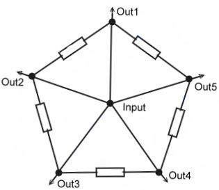
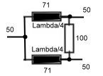
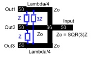
Fig.1 Basic idea Fig.2 50Ohm divider Fig.3 Three port divider
For further readings see :
”Microwave Journal Sept. 85 p. 205
Practical Data’s of Wilkinson couplers are: