|
When I needed to buy somewhere some similar direction coupler for lower VHF bands PA up to 500W, I was not successful. The only simple solution was to develop such device at home. Maybe the below description will be useful for someone, who want to construct SSPA with all protections in his home shack as well as. In the Czech republic are quite regularly used professional directional couplers by Kathrein, dismounted from obsolete GSM base stations of 1st generation. This device is mechanicaly perfect, but the coupling attenuation on 2m is to high to be able use it for stable SWR measurment. As well as the 7/16 DIN connectors are not very often use in regular level ham radio practise. The other, commercialy available directional couplers are not usable for RF power in the range 300 to 800W. Due to it, I set the task for such part (144 & 432MHz):
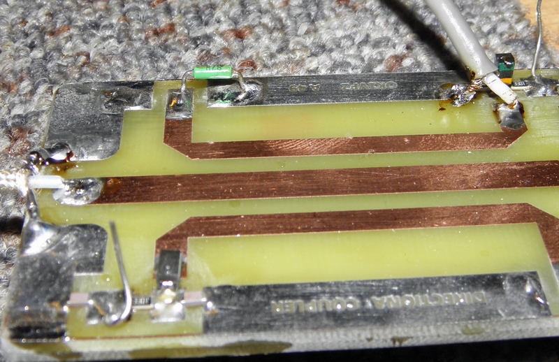
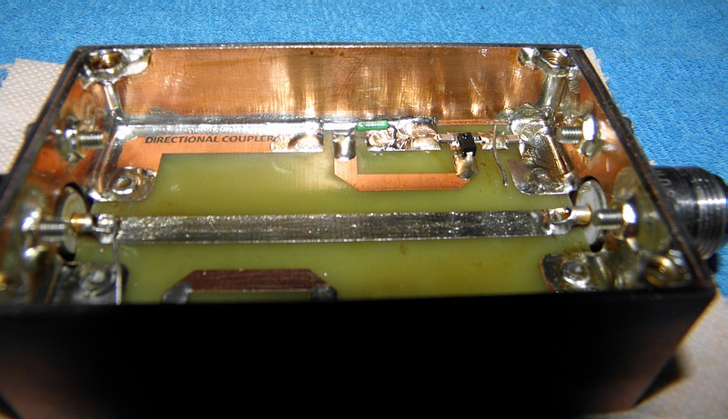
The very first idea was to draw such coupler lines on single, double plated PCB. However: when the ordinary, 1.5 mm thick FR4 laminate is used, the width of stripline is less, than 3mm, what is not enough to transfer the above mentioned RF power (particularly, when operate the FSK mode, like for EME and a MS). When 500W RF is applied, RF current 3,2A warming up the stripline and due to that the RF current is above limit for such mictrostrip width. To transfer the above mentioned power (up to 800W) is necessary increase width of line and it (for 1.5mm thick material) is needed to use PCB with lower dielectric constant, than FR4 have (for example Rogers 3000 family PCBs). However such RF PCB material is not well accessible for home radio shack. Due to that I decided to use rather sandwich construction of directional coupler using two regular FR4 1.5mm thick and only one of them has one side plated lines, which gives 3mm dielectric below the microstrip. It allowed me to increase width of power line. Now the power is not limited even up to 1kW RF. Both single sided boards (the above with microstrip, the bottom one with ground plane) are interconnected by small brass rivets (2.5mm dia, 5mm long). Finally I made two versions – one for 144 (and 70MHz) up to 800W RF and the second one for 432MHz RF, as well as up to 800W. Of course the 144MHz version of stripline is usable for 70cm as well, but due to tight coupling the power on 70cm shall be limited to abt. 150W RF. But it‘s not a fault, because this directional coupler is designed for installation INTO a SSPA, and such QRO PA can’t be commonly used for more bands (due to 2nd. harmonics cutting off by for each band separately tailored LPF).
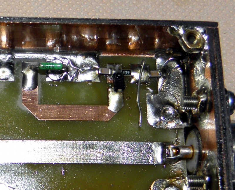
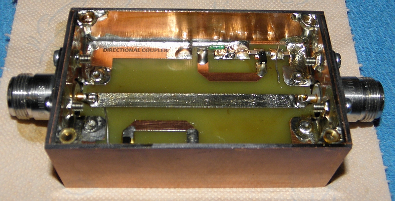
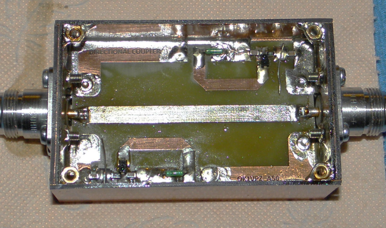
The bord A49 is a directional coupler with more tight coupling, primarily designed for 2m PAs with 100 to 800W RF out. A50 PCB has desidned for 70cm for the same power range. Both of these couplers are not suitable for 23cm. For this band I will publish soon another board for home brewing. When you intend use these coupler, také a care to the connection of cox cables. For 2 m and the PWR up to 500W is good enough simply solder teflon cable (similar size like RG58) , but for higher PWR and for 70cm is better to use install the PCB into a suitable box and use good N connectors. SMD components are 1206 size detection diode is a RF Schottky low signal rectifier with capacity below 1pF and at least 20V reverse voltage. I have there obsolete KAS34 by Tesla, but any similar type is OK. The key component is suitable terminating resistor of the decoupling microstrip. PCB has designed for parallel combinationof two SMD resistors 150 Ω of 1206 size, however soldered resistors have to high parazitic capacity. After some experiments was as a terminator used ordinary 1/4W metalized resistor 82 Ω with wire connections, which is placed there as shown on the pics. Body of the resistor is about 2mm above the PCB plane and the grounded point is inside the coupling loop. (pic) Legth of resistor wires have some inductance, which compensates resistor capacity. Detector blocking capacitors are standard ceramic 2.2nF, seriál resistor 3.3kΩ. If you want to use the directional coupler for SWR protection, you may reverse the diode polarity and use for example this comparator. If you prefer use external detector, connect the coupling microstrip directly to the SMA connector, placed on the side wall of the box. Measured average performance (4 pcs were measured) is in the table.
Let me wish to all, who will try to do this directional coupler, successful construction and lot of fun on VHF bands! 73 de OKVPZ Check the pics below:
|
||||||||||||||||||||||||||||||||||||||||||||||||||||||||||||||||||||||||||||||||

.jpg)