|
World record on 122 GHz, experience and equipment [2014]
A report by OE5VRL and OE4WOG - Beginning Later around 2006/ 2007 season group of DL friends has started further 122 GHz tests. This group consisted of Walter Iller, DH6FAE, Karl Ochs, DJ6BU, Philip Prinz, DL2AM and Jürgen Dahms, DC0DA. In OE the first QSO on 122 GHz was established in 2009 by OE3WRA and OE3WOG over a distance of 1.5 km. The length of the connection was soon extended to 22 km. Due to the possibilities of the first and second generation of transverters and used antennas which were available, this was about the maximum possible distance at that time. In parallel to the activities in DL and OE, tests and trials in OK were carried out by OK1AIY and OK1UFL [they made first QSO on 122GHz on 15th June 2006].
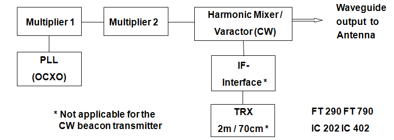
# 01 - The Block diagram of Transverter / CW beacon used for the mm frequency range
In the 1st picture is showed the classic structure of a transverter for frequencies > 100 GHz without an image frequency filter. The chain started with OCXO and fixed multipliers (x 96 / x128). The OCXO was later replaced by the PLL from OE2JOM. The main characteristics: no
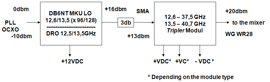
active elements between mixer and antenna, # 02 - Explanation of the used multiplication for 38/40 GHz
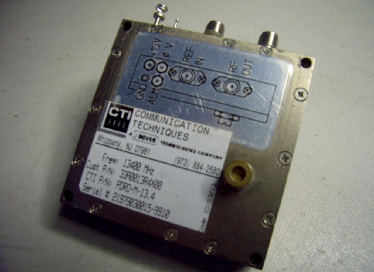
For fixed multiplication (x 96 or 128 times) were used MKU's multipliers from DB6NT (new generation equipped with a PLL) or DRO that allows a flexible LO reference from an OCXO or PLL module. For the 122 GHz band, the reference frequency of 141 MHz must be multiplied e.g. 96 times. Disadvantage: the quartz runs in the 5th overtone, thus w. higher phase noise, thermally difficult. Alternatively: the usage of a DRO (Dielectric Resonator Oscillator). This consists of a ceramic resonator (puck), a comb generator, sweeper and a PLL. The phase noise of a DRO is in the same order of magnitude as that of conventional multiplier stages. The flexible choice of the multiplication factor allows using of lower reference frequencies in the range of e.g. 90 to 105 MHz. #03 - 13.4 GHz DRO (Dielectric Resonator Oscillator) from CTI
At 3rd picture is shown a 13.4 GHz DRO from CTI with an external reference input. Such DROs can be found in satellite LNAs. In commercial directional radio links, DRO is the state of art for LO processing. The tuning range is a few 100 MHz, the DRO-PLL capture range approx. 10 to 15 MHz. A typical reference frequency for "locking" a DRO is e.g. 101.00995 MHz, the DRO then locks on the 134th harmonic. (13,535.33333 MHz x 9 = 121,818 + 432 = 122.250 GHz).
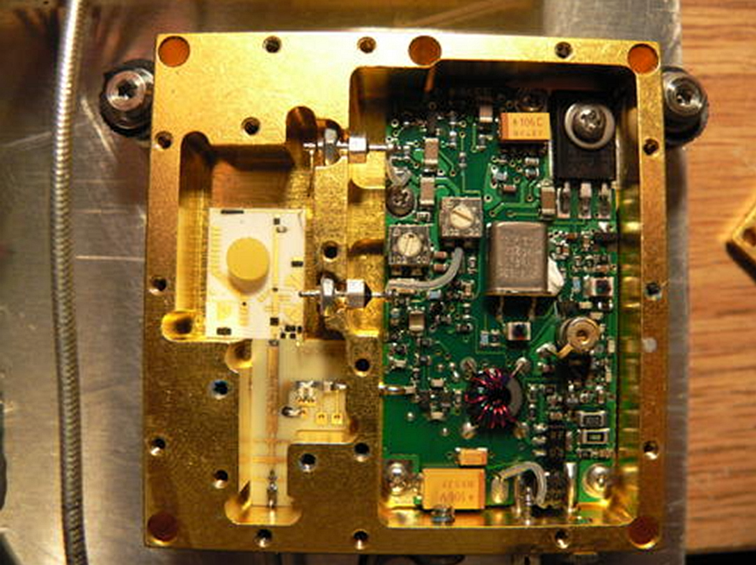
#04 - Inner view of 12,575 GHz DRO with a built-in reference oscillator In the surplus there are DROs with built-in references, these were adapted.
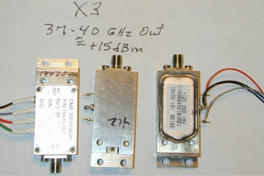
#05 - Surplus Tripler Module operational
from 13 to 39 GHz The second multiplier stage consists of so-called Tripler module which is linear power amplifier (originally made for cell phone network) with 50dB Gain and delivering of 100mW RF output at 38 - 39 GHz. The multiplication to approx. 40 GHz has the advantage that it can be used for 76 GHz (subharmonic mixer x2) and for 122 GHz (harmonic mixer x3). The different models available in the surplus have been described several times by DL2AM. The module has SMA input and WR28 output.
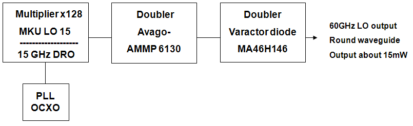
#06 - 60 GHz LO processing for a 122 GHz
subharmonic mixer As an alternative it's possible to create a 60 GHz LO concept for subharmonic mixers for 122 GHz. Walter Iller, DH6FAE, Karl Ochs DJ6BU and Jürgen Dahms DC0DA proposed and implemented this LO concept for 122 GHz. This LO processing, however, has three stages and doubles, first from 15 to 30 GHz and then to 60 GHz. A subharmonic mixer with an anti-parallel diode is used at 122 GHz. Disadvantage: due to the low output at 60 GHz, only RX operation is possible. This 60 GHz LO processing was described by Jürgen Dahms, DC0DA in the Dorsten GHZ conference proceedings 2009 with title: "New receiver mixer for 122 GHz".
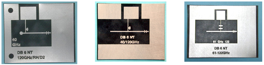
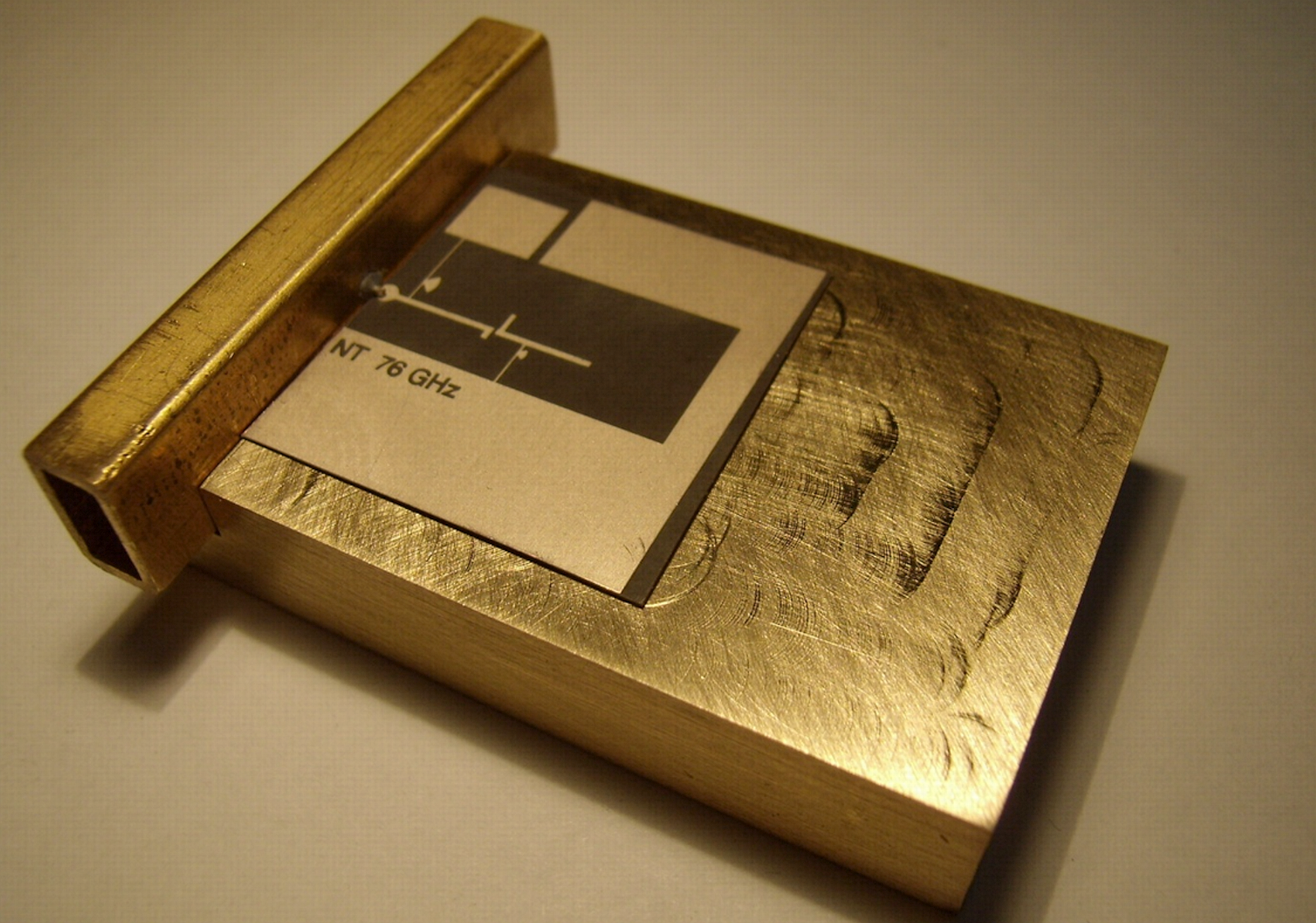
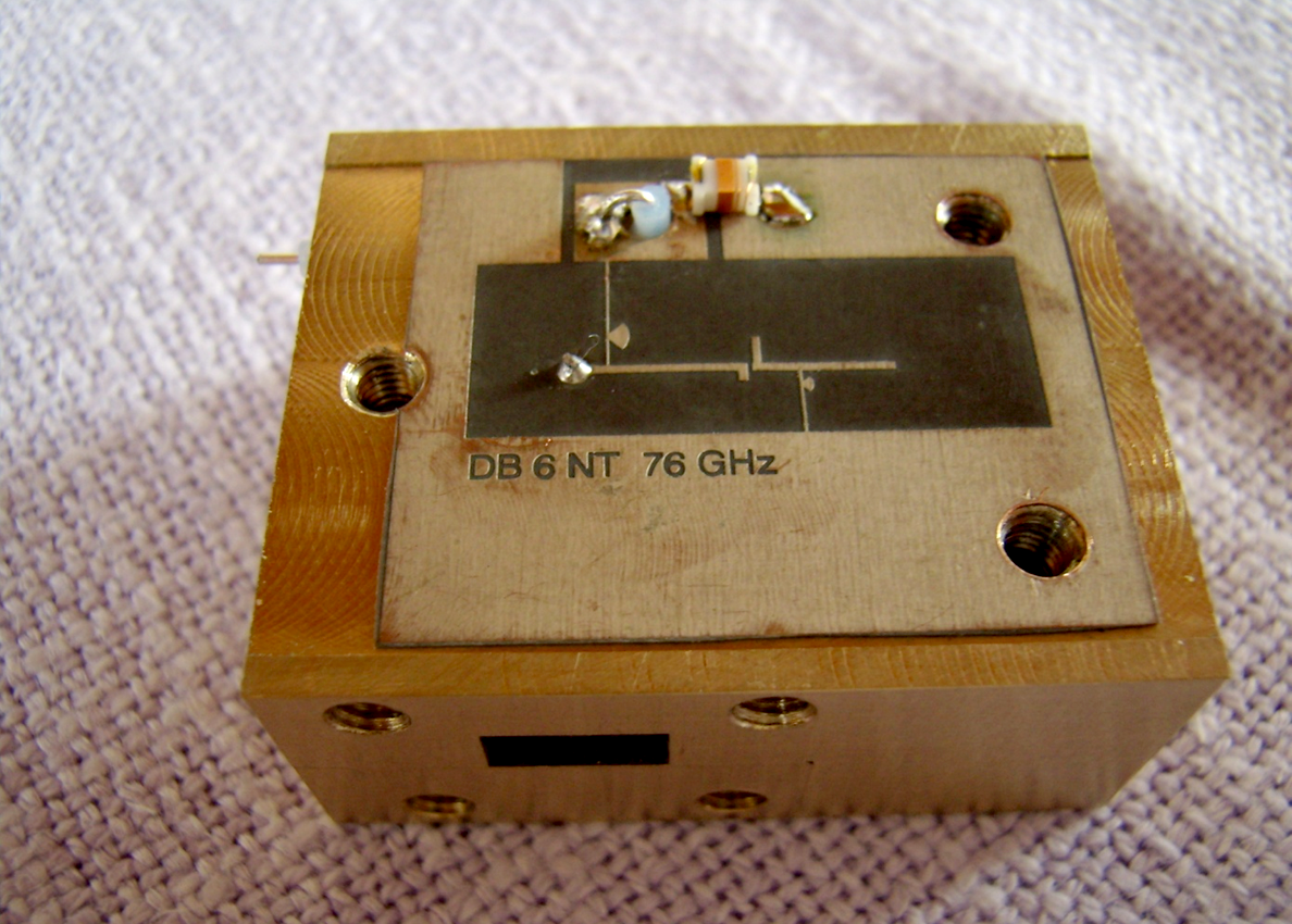
#07 - PCB from DB6NT for 122 GHz mixer / CW transmitter PCBs from Kuhne electronic are available for the mixer design, which allow various connections to the waveguide WR28.
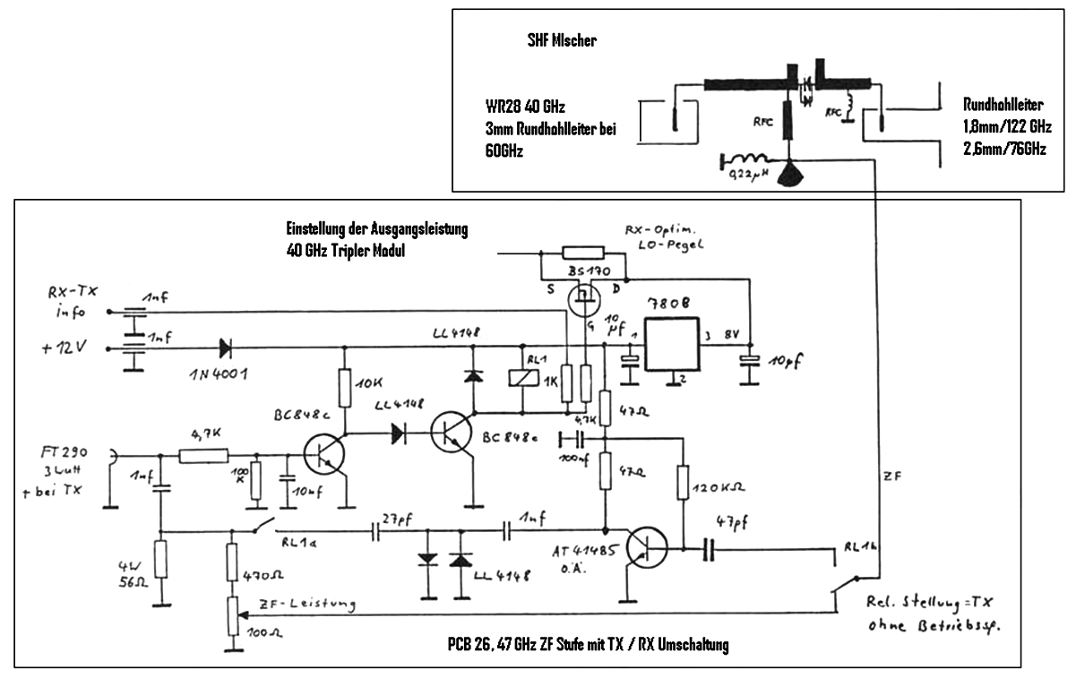
The # 08 picture above shows a subharmonic mixer with an anti-parallel diode. Depending on the diode type, there are differences in the IF connection and for the setting of the operating point. With the single diode you need add a choke as a DC return. Below: The IF amplifier according to DB6NT and the RX / TX switchover with PCB no. 26, the post-converter supplies the positive switching voltage for the RX / TX switchover. In the TX direction, the IF signal is routed via a level control (approx. 50 to max. 100mW). It's advisable to provide a possibility to lower the LO input power at RX and thus to achieve a lower noise figure, if necessary, this depends on the diode and the LO RF level. A change in the diode bias current can also bring some improvements. If we decide to use circuit for CW beacon transmitter, the IF stage and the next stage are omitted. With varactors or single Schottky diodes, the 0.22µH choke (DC return) is replaced by a trimming potentiometer in order to be able to set the operating point. Varactor diodes require a working resistance of 5 to 10kOhm. If we use only single Schottky diodes, lower values should be sufficient.
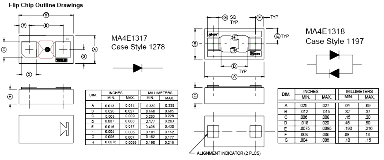
#09 - GaAs flip chip diode housing
The single Schottky diode MAE1310 or MAE1317 is used for the 122 GHz CW beacon transmitter (tripling). When we use a varactor diode at 76 GHz, about 10mW output power is achieved and the power output at 122 GHz is 10dB lower (1mW.) Anti-parallel diodes are used for subharmonic RX mixers and single diodes (MAE1317 or MAE1310) for harmonic mixers. All diodes have the same housing size. In the picture is shown the flipchip single diode MAE1317 from M/A Com. The mechanical dimensions are: 0.66 x 0.33 x 0.19mm.
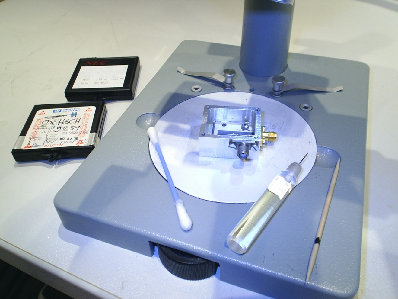
#10 - Gluing of diodes Whether we decide to use Schottky or varactor diodes, the components are glued with the gold-plated connection surfaces (0,2 x 0,17mm) to the stripline of the circuit board thank to conductive silver adhesive.
The processing and installation of flip chip diodes is explained in the descriptions from Kuhne electronic and DL2AM. As you'll see you'll need various utensils and aids, burins, needles, toothpicks, etc.
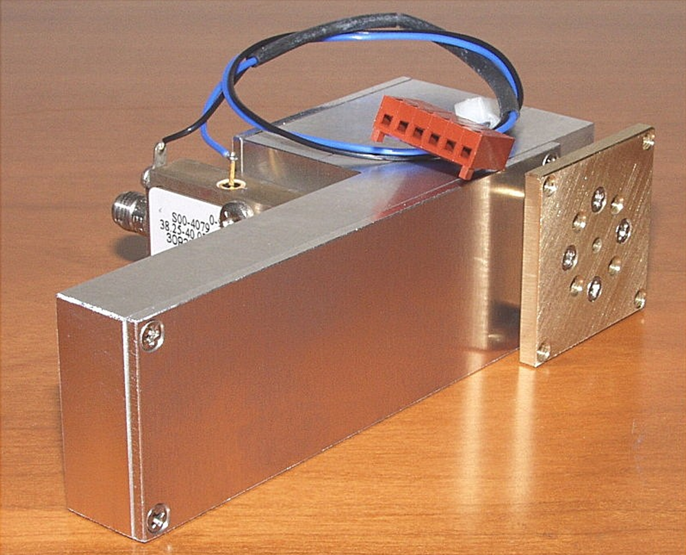
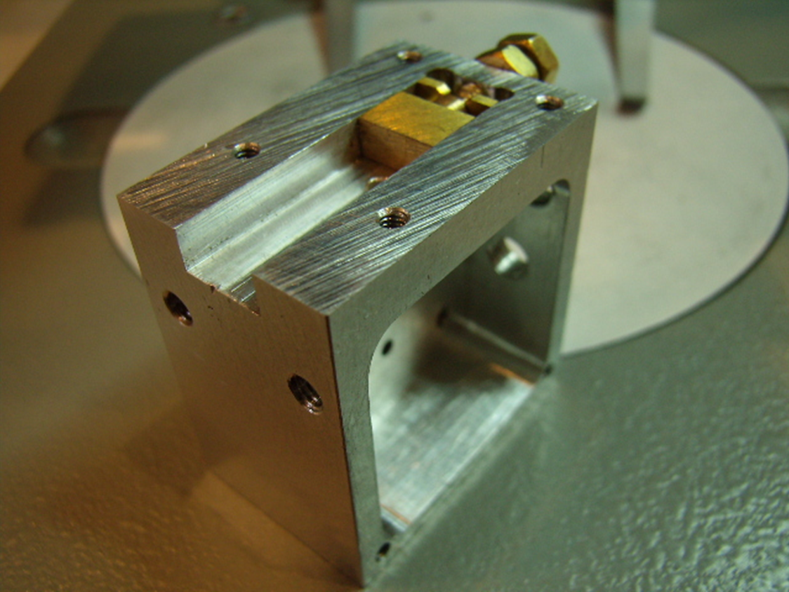
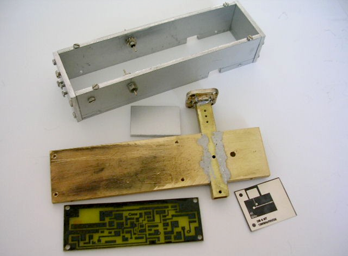
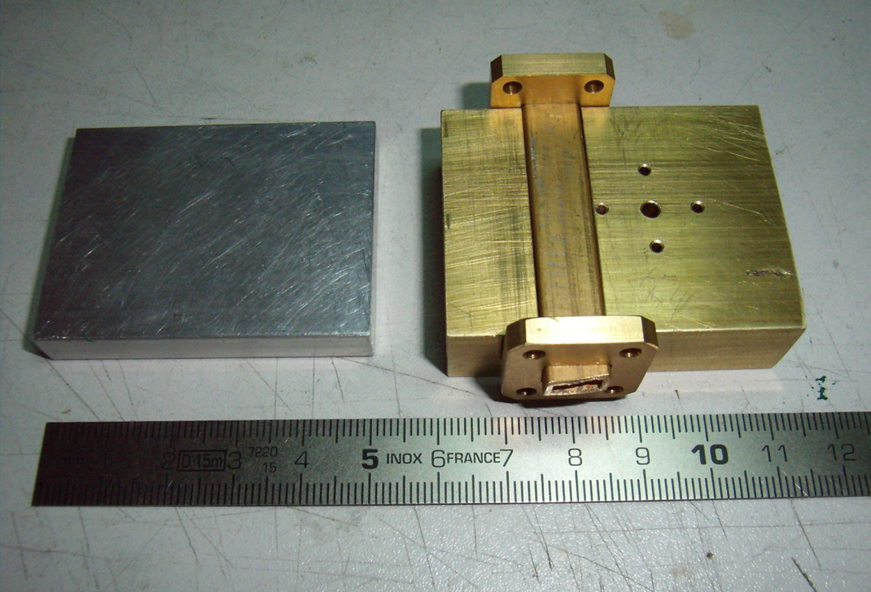
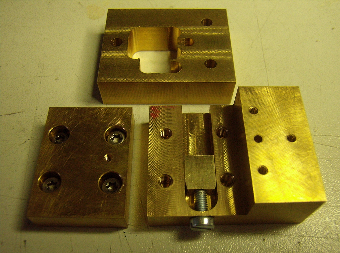
Since the beginning of activity on the 122 GHz band, a large number of HF housings have been developed to accommodate the mixer PCBs. In the picture above can be seen 3-part housing from OE5VRL with a compact and slim profile.
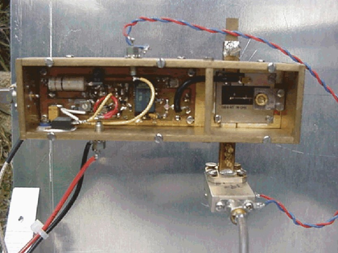
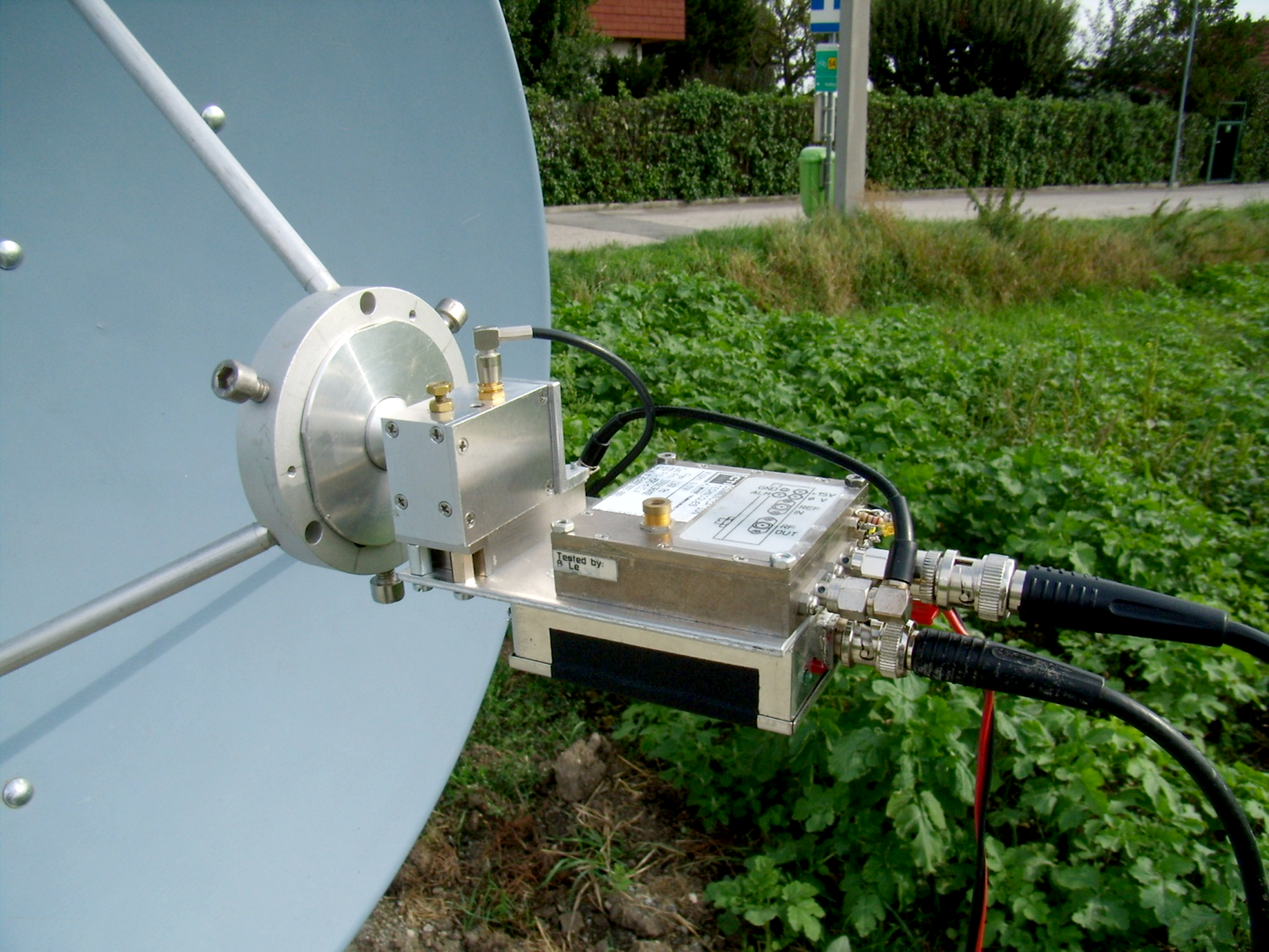
The picture above shows a 122 GHz 1st generation of OE5VRL's transverter mounted in the focal point of the antenna.
The picture above shows 2nd Generation of 122GHz transverter made by OE3WOG with 13.5 GHz DRO, antenna holder has still dimensions of 20mm, however it's still using 70cm KEPS antenna and reference from an external OCXO.
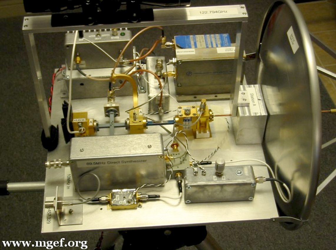
The picture above shows 122 GHz transverter from WA1ZMS and W4WWQ (W2SZ) which was used in year 2005 for breaking the World DX record.
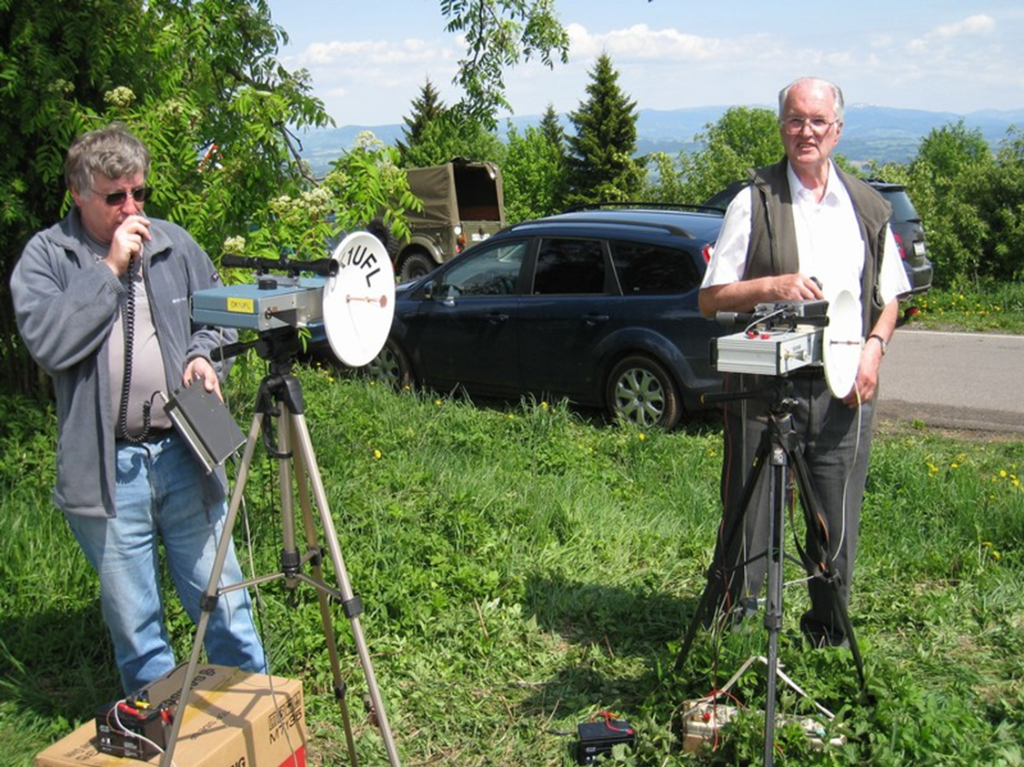
The picture above shows the 122 GHz systems of OK1UFL and OK1AIY (right in the picture). The movable tripod head has an elongated housing in which the transverter and the CW beacon transmitter are installed in parallel. Each device has its own antenna, e.g. parabolic antenna and / or rectangular horn. The CW beacon at horn is running at the same time and it helps with critical beaming of sharp main dish lobe.
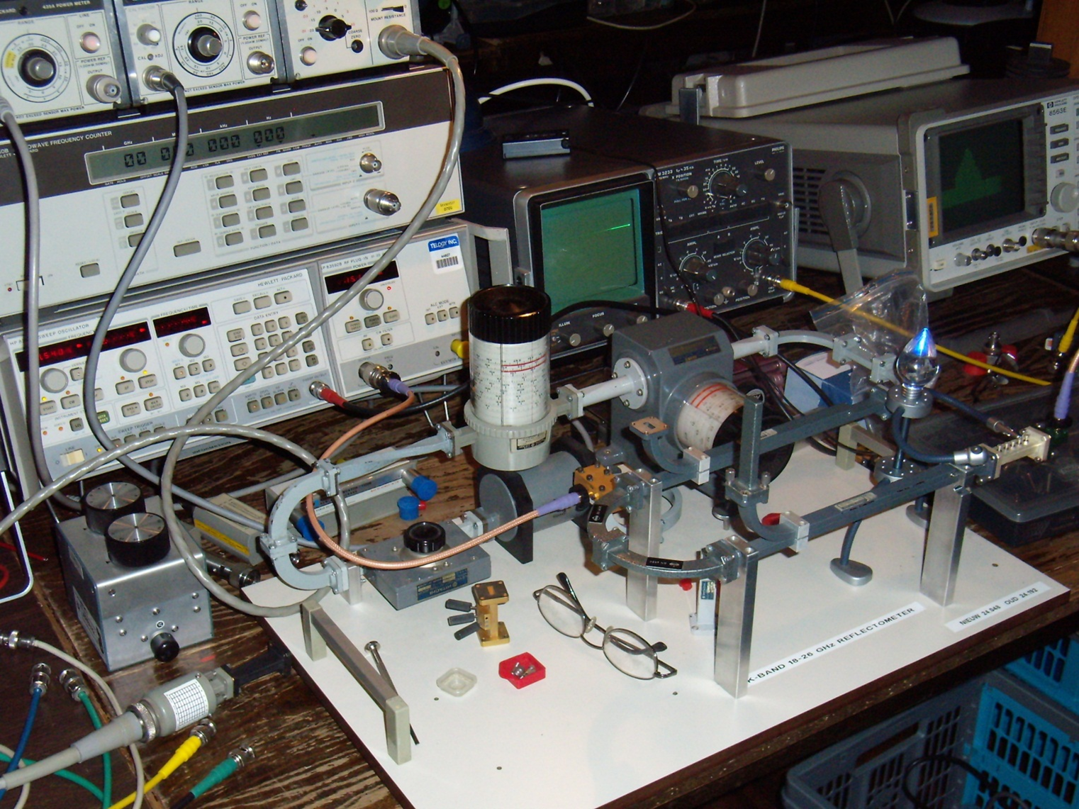
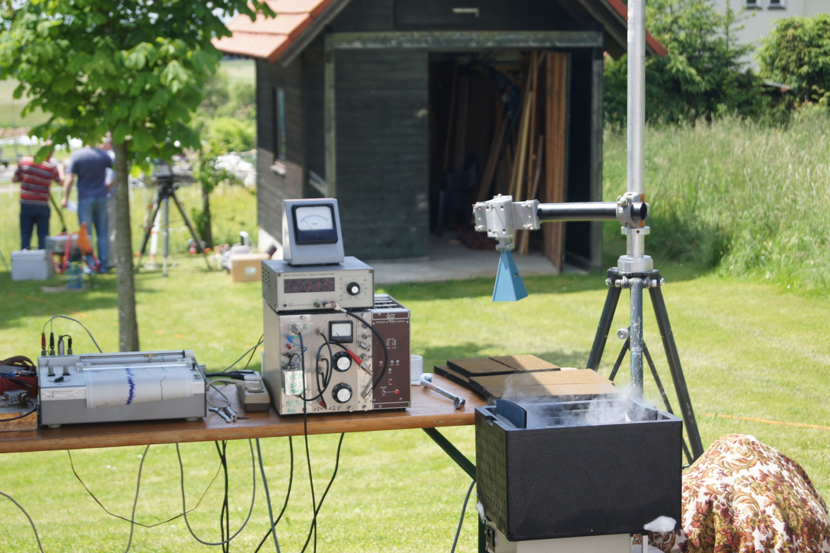
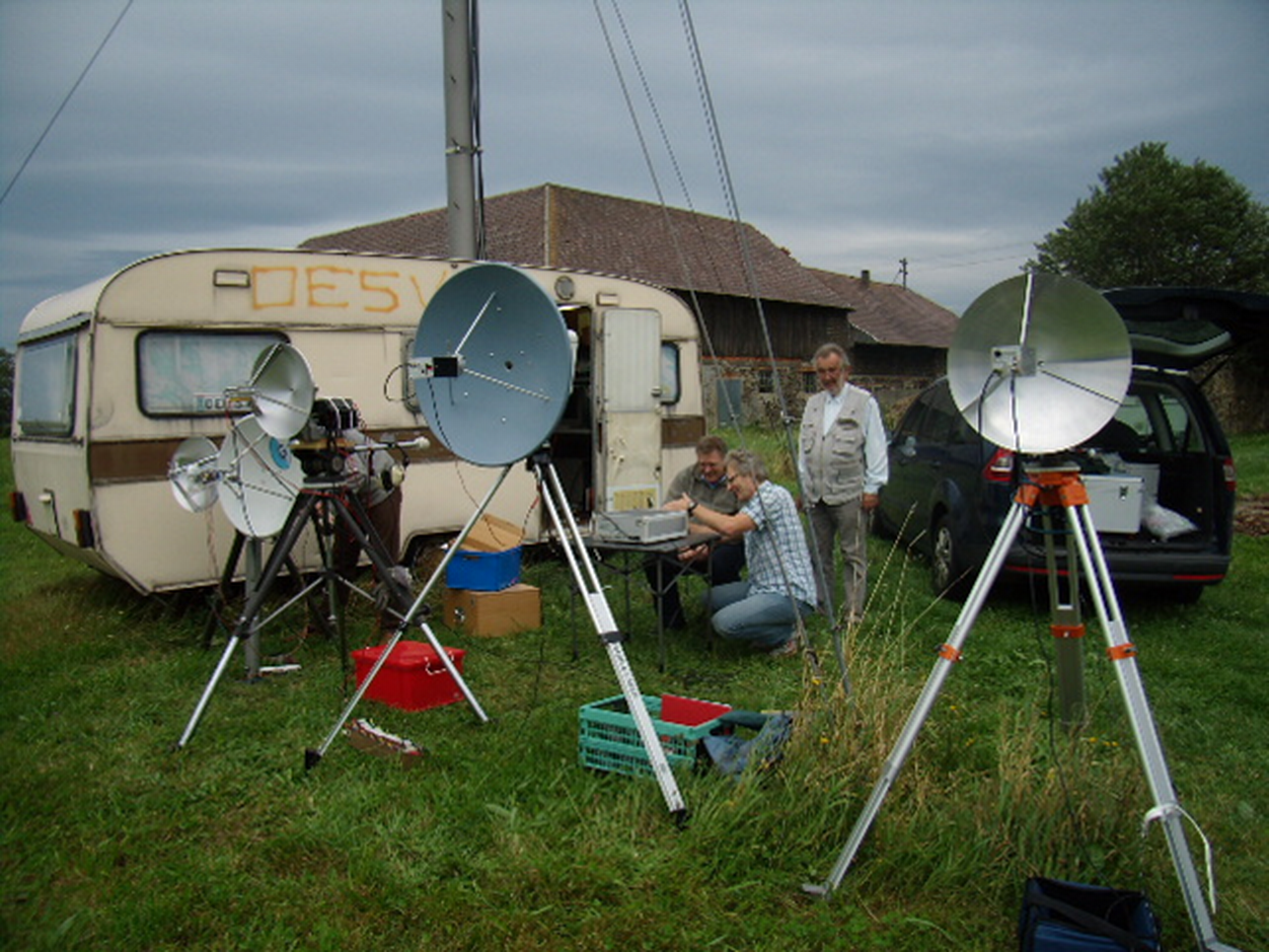
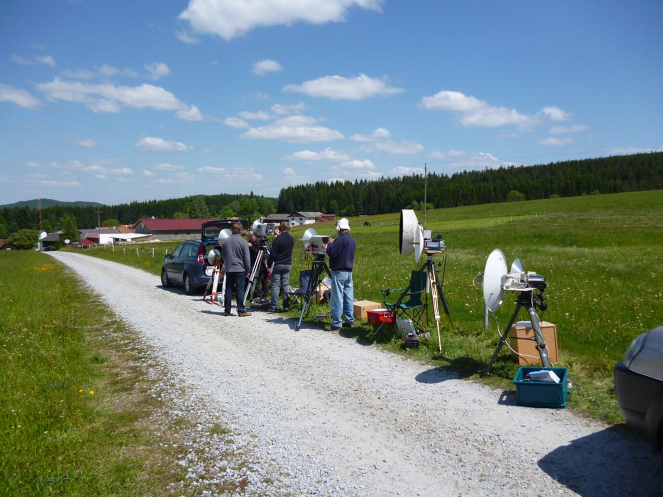
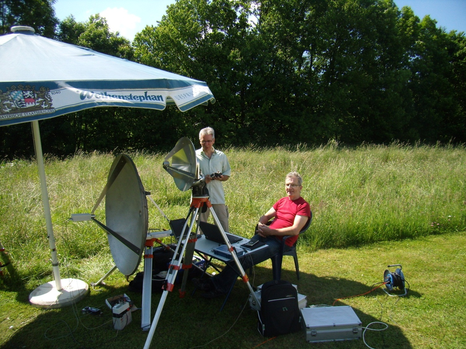
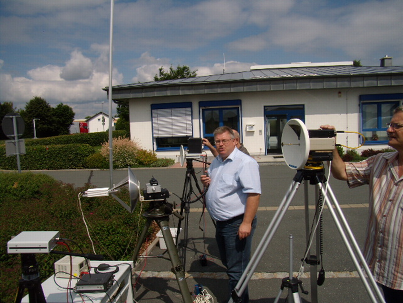
The measurement effort in the mm frequency bands is essentially reduced to: Power measurement, noise figure measurement, frequency measurement, signal strength, secondary reception properties and signal purity (if it doesn't contain any undesired secondary emissions). Thank to usage of OE2JOM's PLL as a reference, frequency measurement has become practically obsolete. However, the power and noise figure measurements are more difficult to accomplish. Participation in microwave round tables and events at which commercial measuring devices are often made available helps a lot. (Hohenbachern, Munich, Dorsten, Heelweg, etc.) see pictures: Heelweg and Hohenbachern.
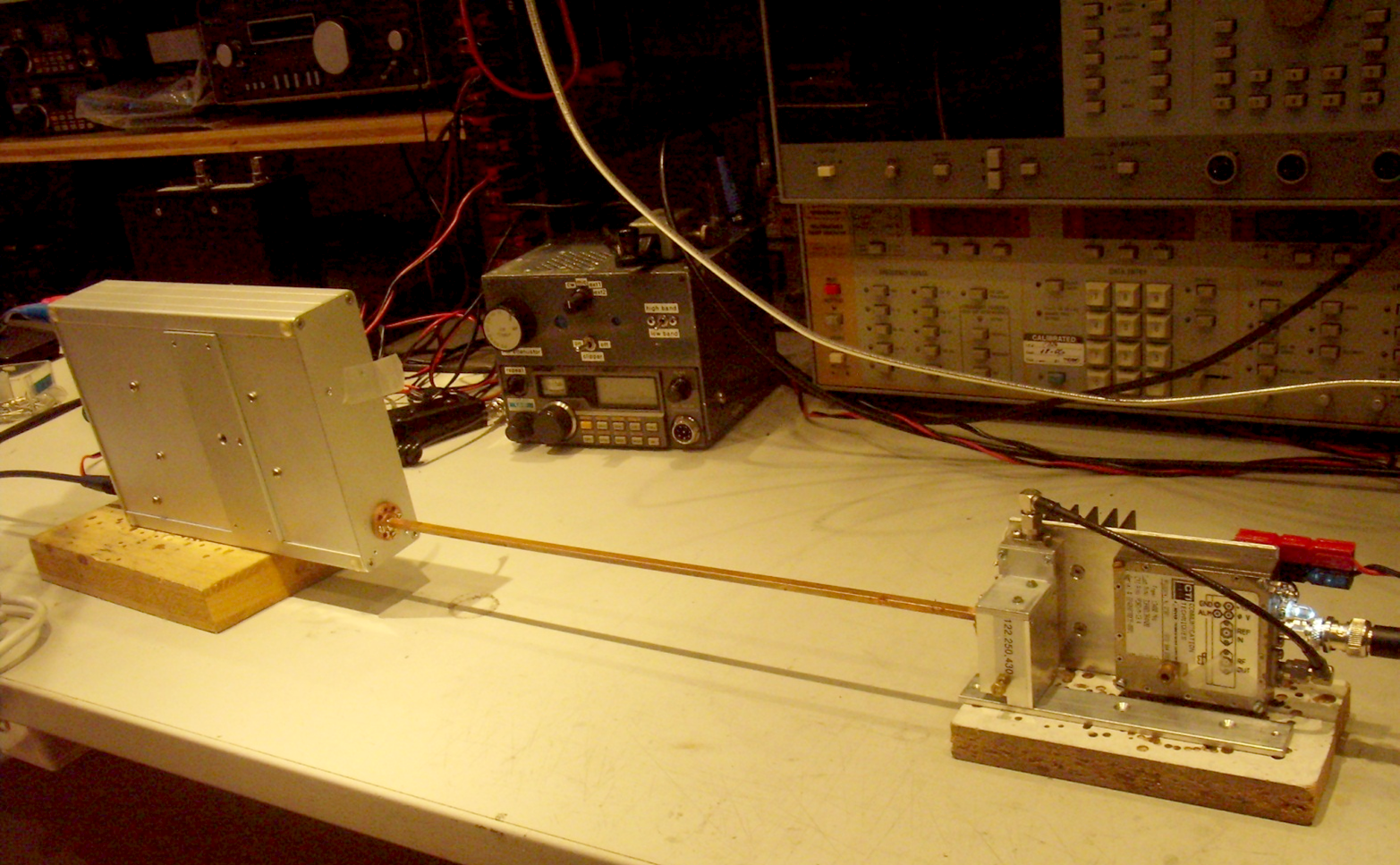
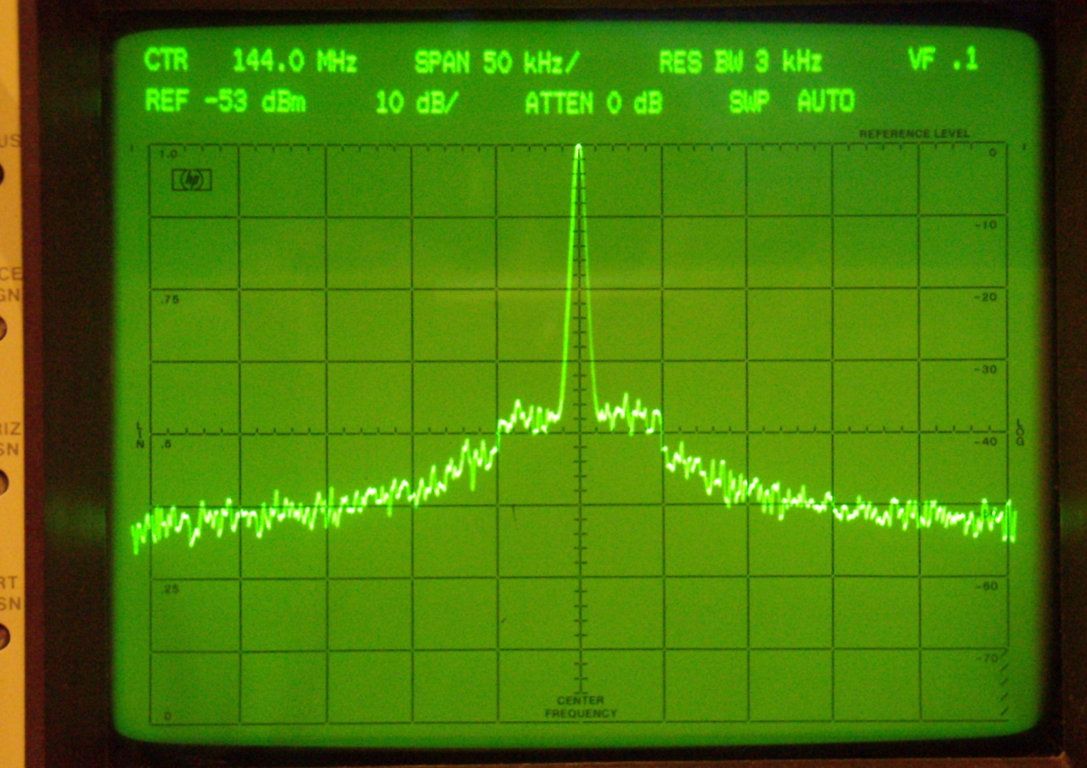
Otherwise one can help oneself with the simultaneous construction of a CW transmitter and a transverter, with mutual adjustment the devices are mutually optimized. e.g. measure the RF level using a spectrum analyser in the IF level. In OE we meet regularly for radio field tests for benchmarking and the exchange of experiences.
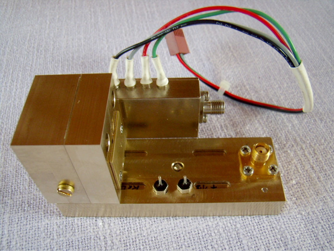
In the picture above is
showed the 122 GHz CW transmitter with 1mW output made by OE3WOG with DRO
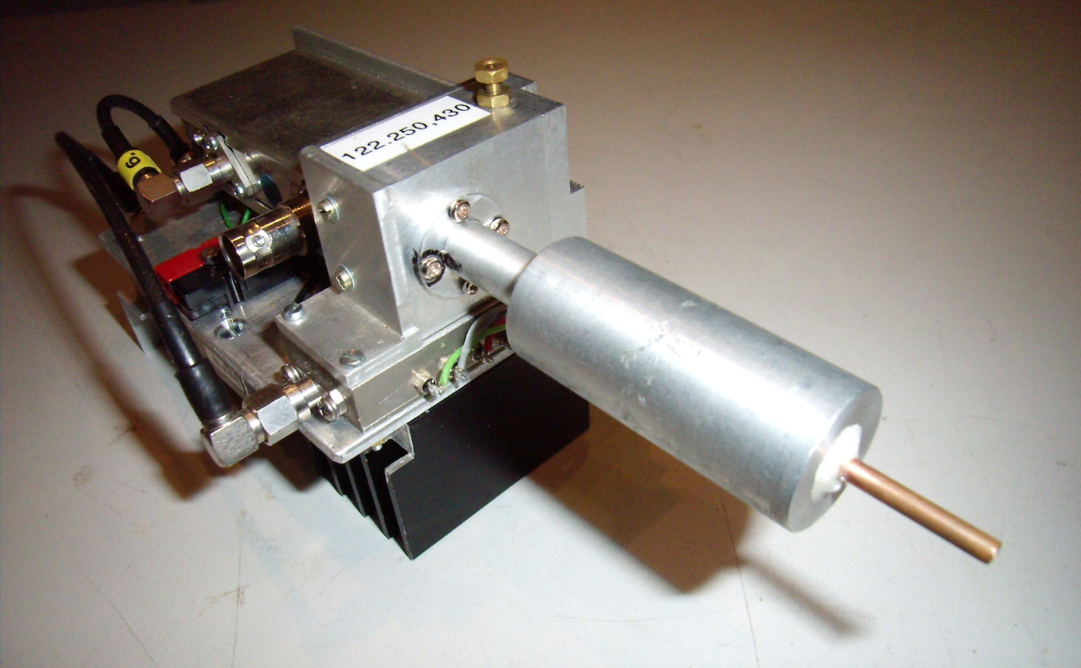
and PLL (Version 2013) The next picture shows the 122 GHz transverter and
CW transmitter from OE5VRL.
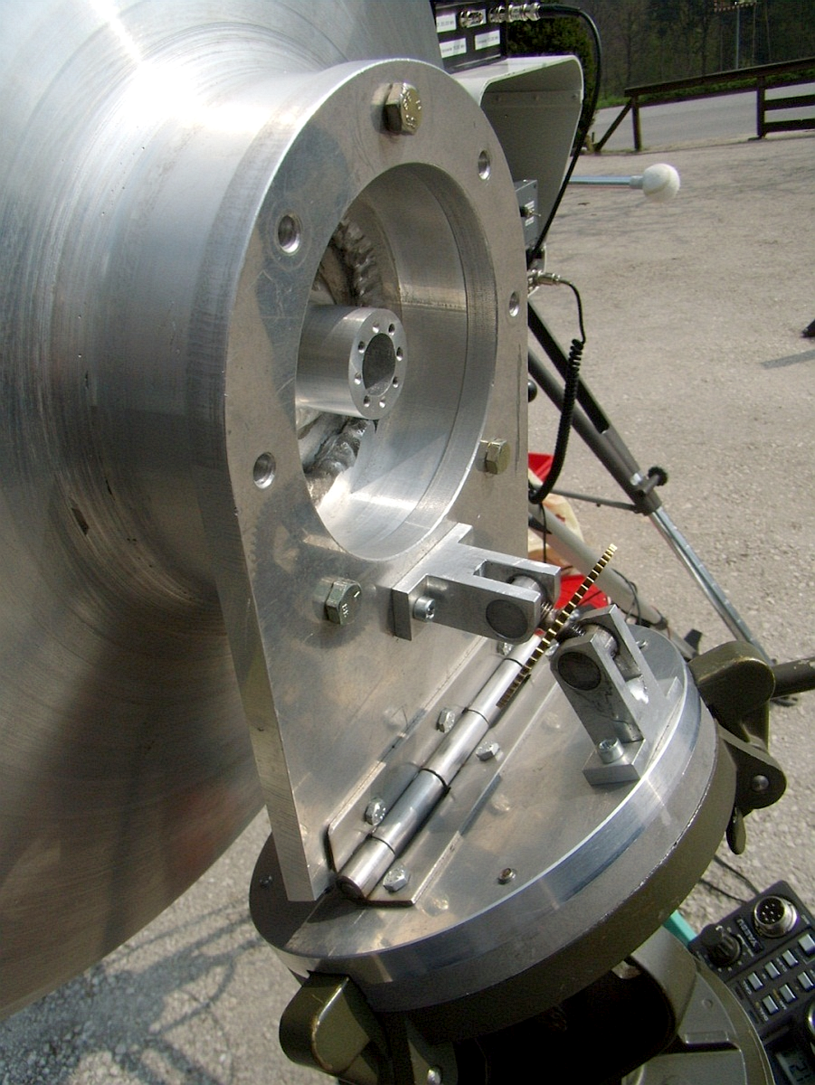
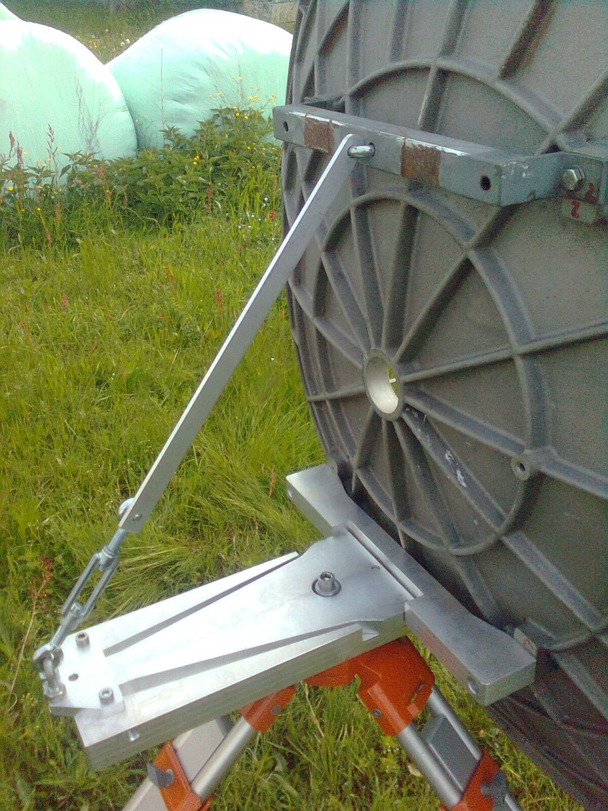
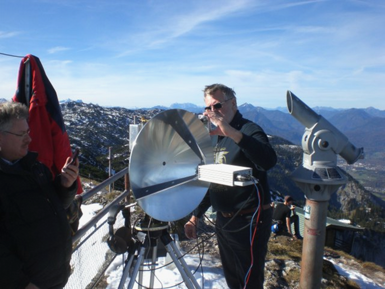
All parabolic antennas currently used on the mm bands in OE are made of solid aluminium and have been manufactured by using a CNC machine. The 121cm antenna (35kg) is also made of solid aluminium, but comes from a commercial production. Appropriate precautions were therefore necessary to adjust the 121 cm antenna, see picture. A regular meeting of the mm enthusiasts with an exchange of experiences and with equipment and field tests is essential for success on the mm bands.
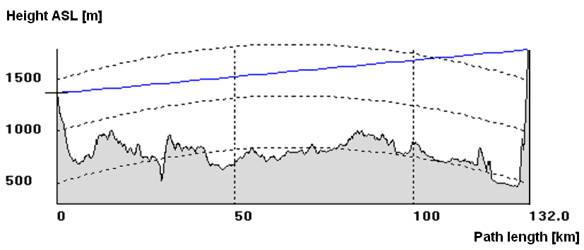
The conditions for the distance record at 122 GHz: in the picture can be seen the cross-section of the terrain from Plöckenstein to Untersberg, the path is LOS, including a free Fresnel zone.
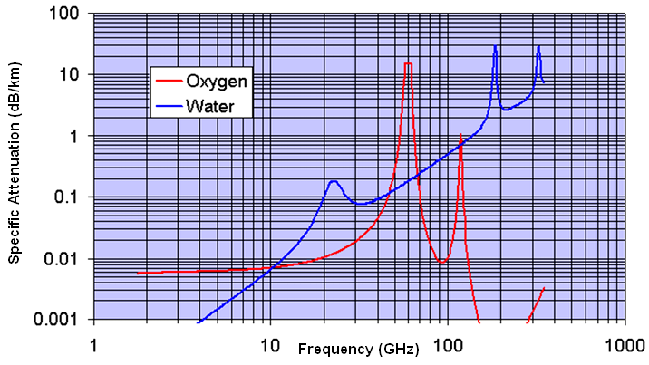
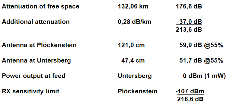
On the mm frequency bands, in addition to the frequency and distance-dependent radio field attenuation, the so-called additional atmospheric attenuation is added.
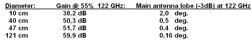
According to the table above, the received signal was approx. 5 dB above the audibility limit of our receiver, although we knew from various tests in advance that the equipment used was not the same at the last 1 dB. The CW transmitter from OE5VRL had about 3 dB less output power (-3 dBm) but on the OE3WOG's side the RX mixer was more sensitive so the differences were more-less balanced out again. We had divided the devices in such a way that the prerequisites for a possible success were roughly the same. If the additional attenuation had been only 0,05 dB / km higher (6,6 dB / 132 / km) the QSO would not have worked. Regarding the use of parabolic antennas in the mm range, it should be noted that success is only feasible with really precise antennas. In a test in 2010 we found that a 65cm DISH from SAT television showed just 1 dB bigger gain on 122 GHz than a precisely manufactured dish with 10cm diameter.
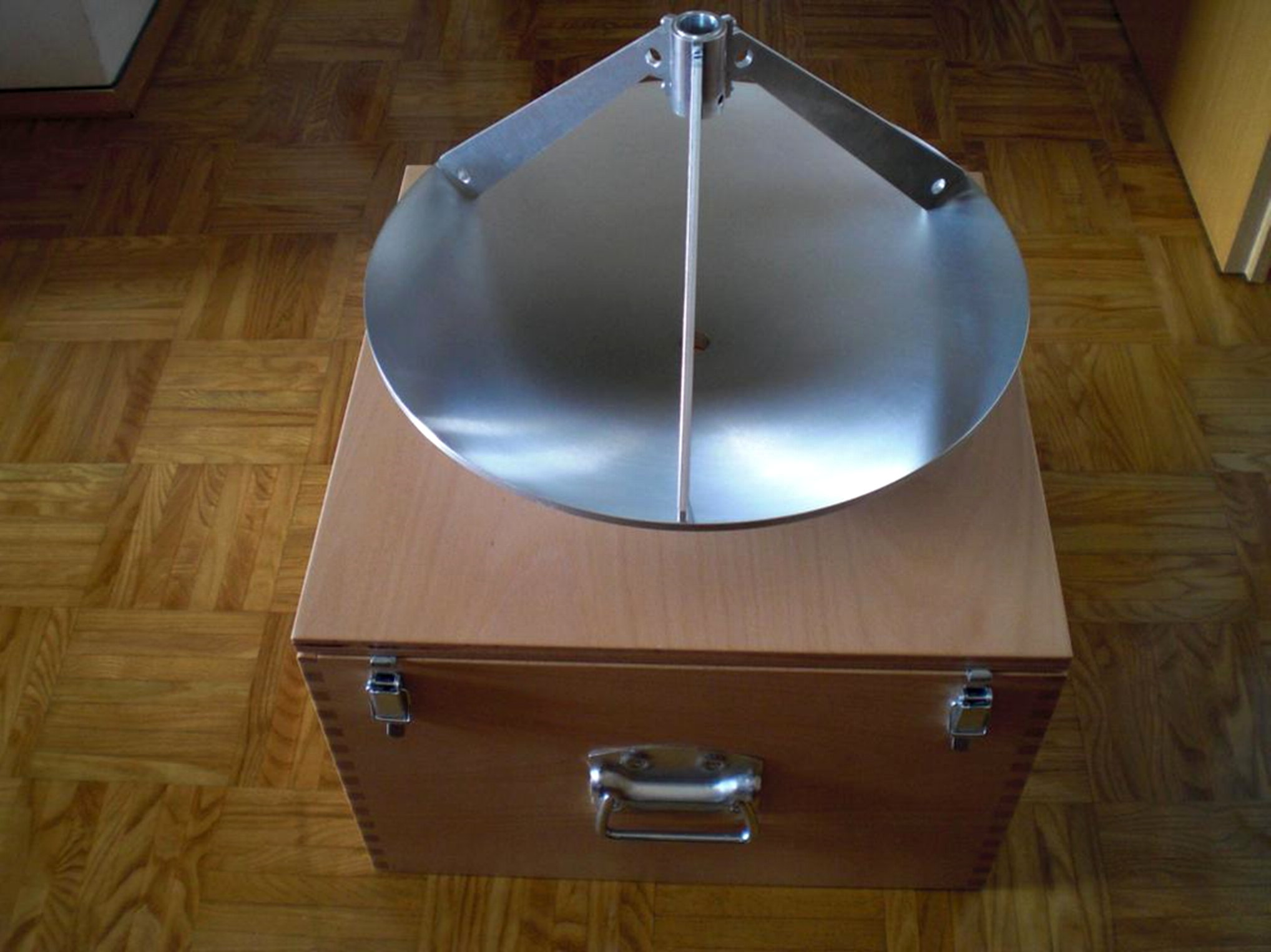
We have been using the system with the 20mm feed brackets since the beginning of our activity on the 76 and 122 GHz bands. Exactly in front of the focal point there is a sleeve mounted on a tripod with a 20 H6 bore. In this hole the radiator together with the transverter or CW transmitter is pushed in from the front and held mechanically. This also makes it possible to exchange equipment in a short time. When testing the microwave bands, it makes sense to first align the antenna at a lower frequency (10, 24, 47, 76 GHz) and then switch to the next higher band. The antenna is readjusted again and again. (as higher we go in frequency, the opening angle is decreasing). To illuminate the dish, we use suitable open round waveguides for all frequency bands from 10 GHz. The mechanism is designed in such a way that the transverter is pushed into the holder as far as it will go, so that the radiator is exactly in the focal point. Our self-made mirrors as well as the commercial 121 cm mirror have an F/D ration of 0.4. Since we all use the same assembly principle for the feed, we are compatible, which makes it easier to compare the devices. We use self-made dishes (made on a CNC lathe) with a diameter of 10cm, 40cm, 47cm, and a professional dish (aluminium) with a diameter of 121 cm.
In order to be able to position the antenna precisely at these small opening angles, a stable mechanism is necessary. Threaded spindles are ideal for fine adjustment. Of course, the tripod must also be robust in order to provide a stable and windproof platform.
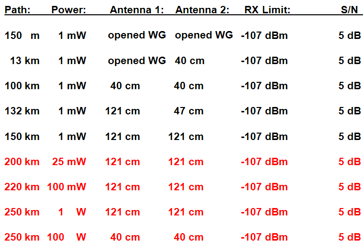
Examples of what effort is required on both sides to get over the different radio paths.
YouTube Videos related to our 122 GHz topic:
http://www.youtube.com/watch?v=JlgoepVF43E
http://www.youtube.com/watch?v=cynX4VD2n6Q
http://www.youtube.com/watch?v=E6LP6hBSeIY
http://www.youtube.com/watch?v=SHrMtOXnf98
http://www.youtube.com/watch?v=OMronFbILRY
Future projects:
60 GHz LO for 122 GHz
Subharmonic mixer
?
TNX OE4WOG & OE5VRL for approval to put their presentation at OK2KKW web - edited by OK1TEH |
||||||||||||||||||||||||||||||||||||||||||||||||||||||||||||