|
G2 voltage
regulator.
A G2 voltage regulator is a very important part of tetrode PAs. It must
work as a parallel regulator, since the current can flow not only in, but
also out of the G2 especially at higher drive. This current must be
absorbed in the regulator without changing the G2 voltage. .
Why can the current flow out of the G2? There’s following effect that
occurs at higher drive. Electrons emitted from cathode flying along the G2
are attracted more by the anode, since it’s on a higher potential then G2.
A small part of them is captured by G2 and causes normal G2 current
flowing into the grid. The electrons that land on the anode can strike
other electrons within it. This effect is called secondary emission.
Normally these electrons land back on the anode due to its higher positive
potential. However, when the drive exceeds certain level, i.e. the
amplitude of the AC anode voltage increases, the instantaneous anode
potential can get under the G2. At this moment the secondary emitted
electrons start to strafe G2 and the G2 current flows in opposite
direction then usual. This effect is known as dynatron effect and it
creates a negative internal resistance, a “hump” on the tube
characteristics. This problem can be solved by adding of another (third)
grid very loose winding between G2 and anode whose role is to capture
secondary electrons (the resulting tube is the pentode). The third grid
must be on ground or cathode potential in order to work properly.
Unfortunately, this increases the capacity cathode-anode. For this reason
there are no pentods on the frequencies over 100 MHz.
The voltage regulator described in this article can (except of the usual
voltage regulation) also absorb the current flowing out of the G2 and keep
the voltage stable at all circumstances. The voltage is determined
exclusively by the junction voltage of the Zener diods or transistors.
These transistors have relatively low amplifying factor (10-15), which
eliminates any oscilations. All circuits with operational amplifiers or
many transistors with the high gain in the regulation loop (sometimes over
1000!) (as we may see in some articles) are potential source of trouble.
Be aware that 144 MHz can get everywhere!
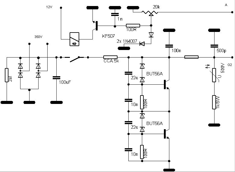
The regulator is a simple classical circuit, the Zener diodes are blocked
with capacitors to avoid their noise. The value of the resistor should be
calculated according to the voltage of the transformer for the current
about 100 mA. Except of the basic regulator there are some additional
protection circuits in the design. A varistor/resistor combination is
connected to the output of the regulator, direct to the G2 and a fuse
(about 200mA) is put between the G2 and the regulator in case a discharge
occurs for some reason in the the tube (typical for tetrodes). If a
discharge occurs the fuse will blow and split the regulator from G2. The
varistor then cuts off the voltage peak on G2 while the resistor limits
the discharge current. Without the protection the huge current caused by
the charge of the capacitors in the anode power supply would flow through
the regulator and destroy the transistors and/or Zener diodes. Another
protection circuit switches off the G2 voltage in case the anode voltage
gets permanetly lower under the G2 voltage. This is a very dangerous state
for the tube, because G2 becomes an “anode” then and takes over the whole
anode current resulting usually in the blowing of the G2 and destroying of
the expensive tube. To avoid this a relay controlled by anode voltage can
cut off the G2 from the power supply .
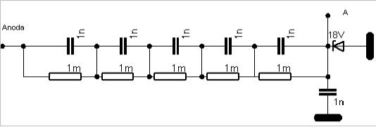
This is the circuit for the relay control. Note that there’s a high
voltage on the resitors and capacitors. They must be sized accordingly. !
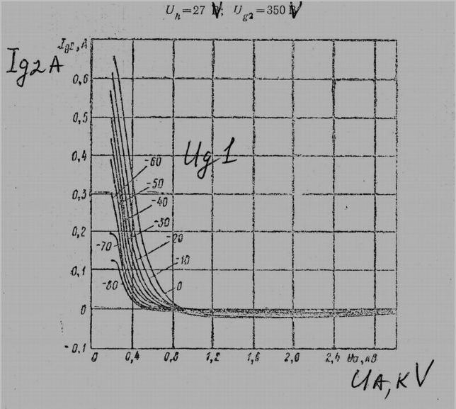
A characterictics of the G2 grid current depending on the G1 and anode
voltage for the tube GU78b. Pay attention to the spot where the current is
zero!
|