Quality of SSB signal in Kenwood TS 2000 on 23 cm
by Dimitrij RA3AQ on 18.th April 2006
Copy of the article published here:
http://www.vhfdx.ru/content/view/347/40/
Already by many was noted the terrible quality of SSB
signal on 23cm from Kenwood Ts-2000x
transceiver. Reason of
it has been proven to
be simple - output amplifier on module MITSUBISHI M57762 works in the deep class
C.
Control of module is achieved by signal 12TXB which it
ensures the bias voltage only about 6.8V DC in the
regime of the transmission, instead of
9V, as indicated in
the documentation. This bias voltage is given to the
pin 3 of module. Module begins to work linearly with
the voltage aprox. = 8V. The current, consumed on the
bias circuit of module is aprox 0.31A with 8V and
grows to 0.35A with 9V of bias.
For guaranteeing the linear operation of the output
stage it was necessary to place additional controlled
stabilizer. As this
stabilizer it is possible to use integrated circuits
such as BA09CC0WT, BA08CC0WT, KA78R08C, KA78R09C or
analogous. Possibility of use of
usual stabilizers, such as LM7809 is possible, but
then is necessary to add control
circuit by discrete devices.
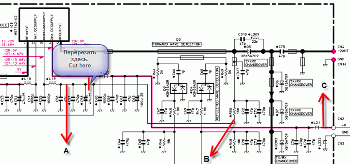
On the schematic diagram is a modifications, which
are necessary to fix the problem, here:
To the point "A" will be given the new
bias voltage of module (8 or 9V, depending on the used stabilizer.
From the point "B" is taken the signal for control of the microcircuit of
stabilizer. Voltage at this point is present only
during the transmission. The
input voltage of stabilizer is taken from the point "C".
In the case of applying the diagram of control on the discrete elements
still will be required earth (gnd).
Modification step by step:
1. unscrews the upper and lower covers of transceiver.
2. unscrew from the side the transceiver the cover, which fix
the 23cm module Ut-20.
3. unscrew the metallic cover, which closes the space of
supply connectors
4. detach the flat cable, which goes to board
Tx-rx1 UNIT (HF/IF) (CN27). Remaining joints it is possible not to touch.
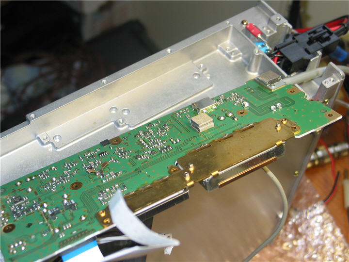
5. loose the screws, which fixing
the board to the housing and then
turn over carefully the board as shown on the
picture:
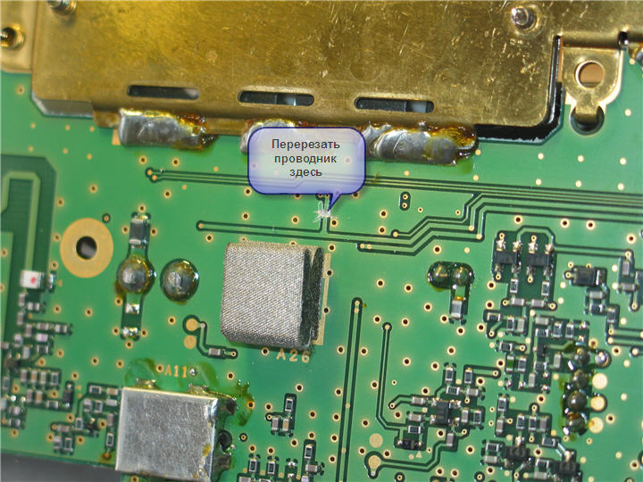
6. Cut of printed path as shown on picture and put the board back in the place.
7. install stabilizer beside in the supplying box space as shown in figure. In this case the terminal, which connects varistors with the earth can be transposed under the screw of fastening metallic cover.
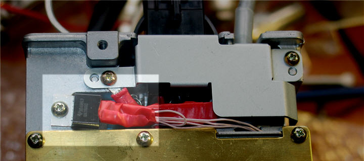
8. connect by the wires point "A", "B" and "C" with the stabilizer as on the picture (we do not forget, if it is necessary, about the capacities at the entrance and the output of stabilizer.)

Everything, it is possible to turn all screws conversely.
After this mofication all stations noted that quality SSB of signal on 23cm became the same as on 2 m band.
______________________________________________
Used automatic translation from Russian with few corrections by OK1VPZ.
Sorry, the original high resulution pics are not available any more (2022).