|
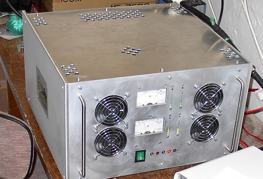
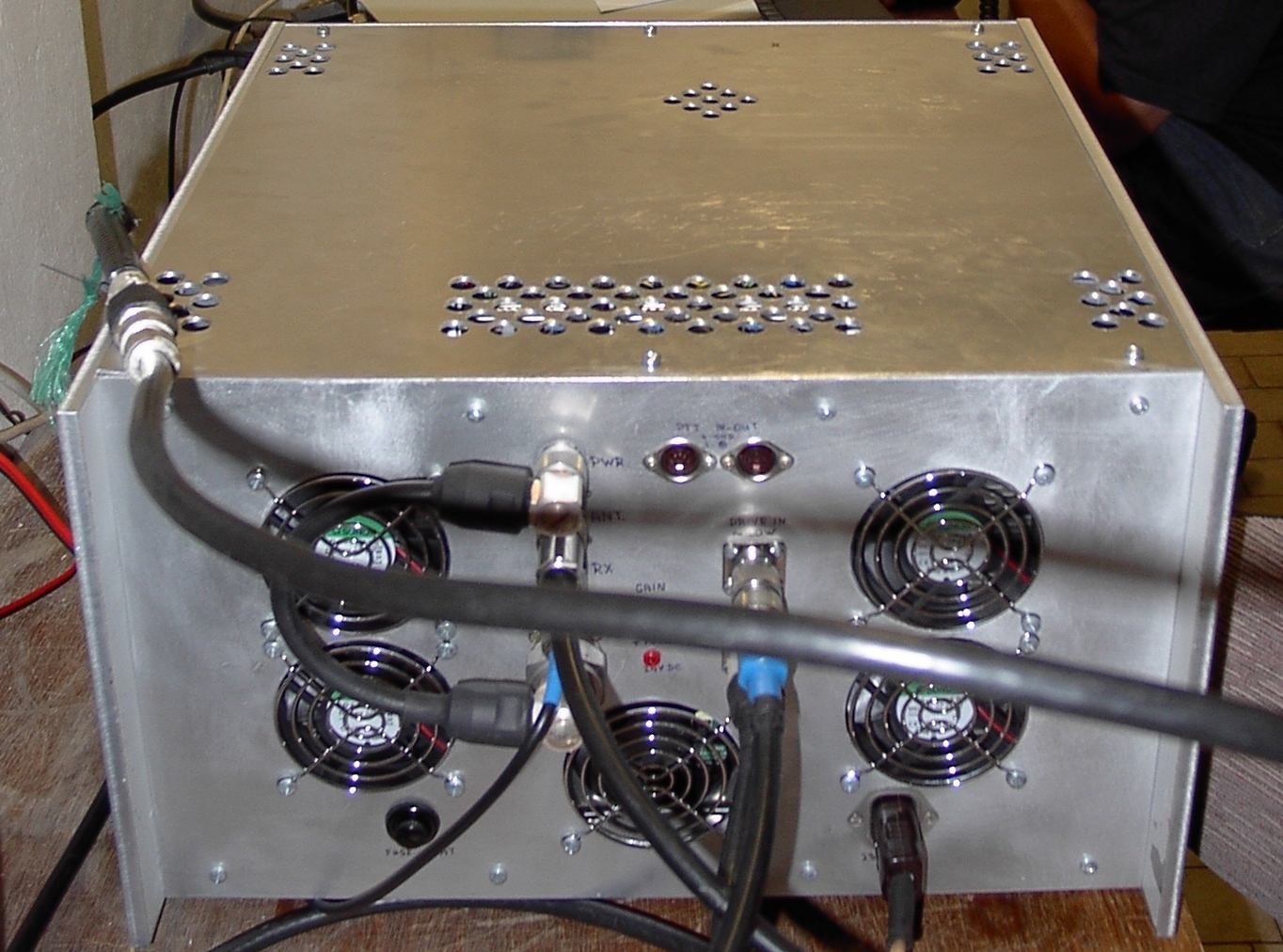
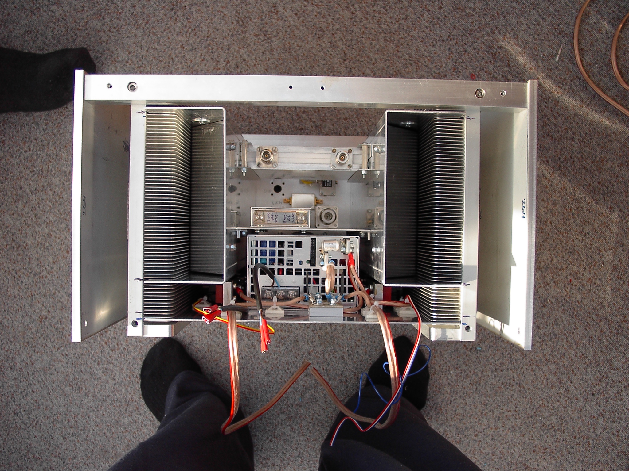
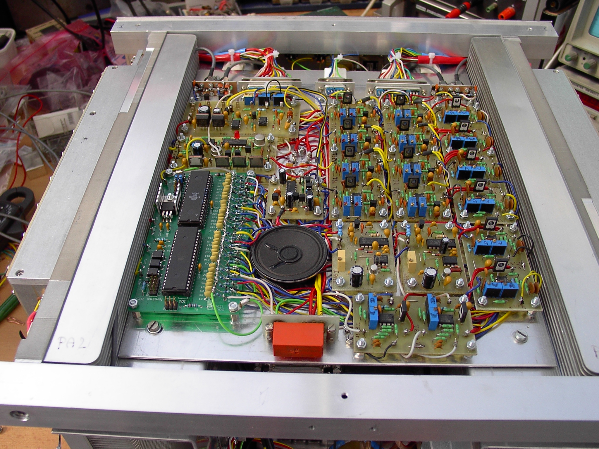
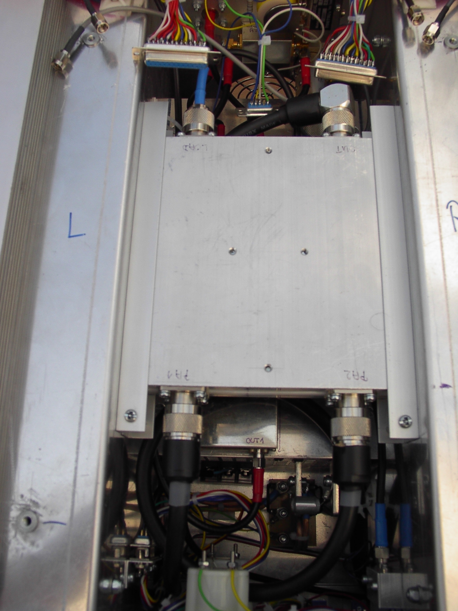
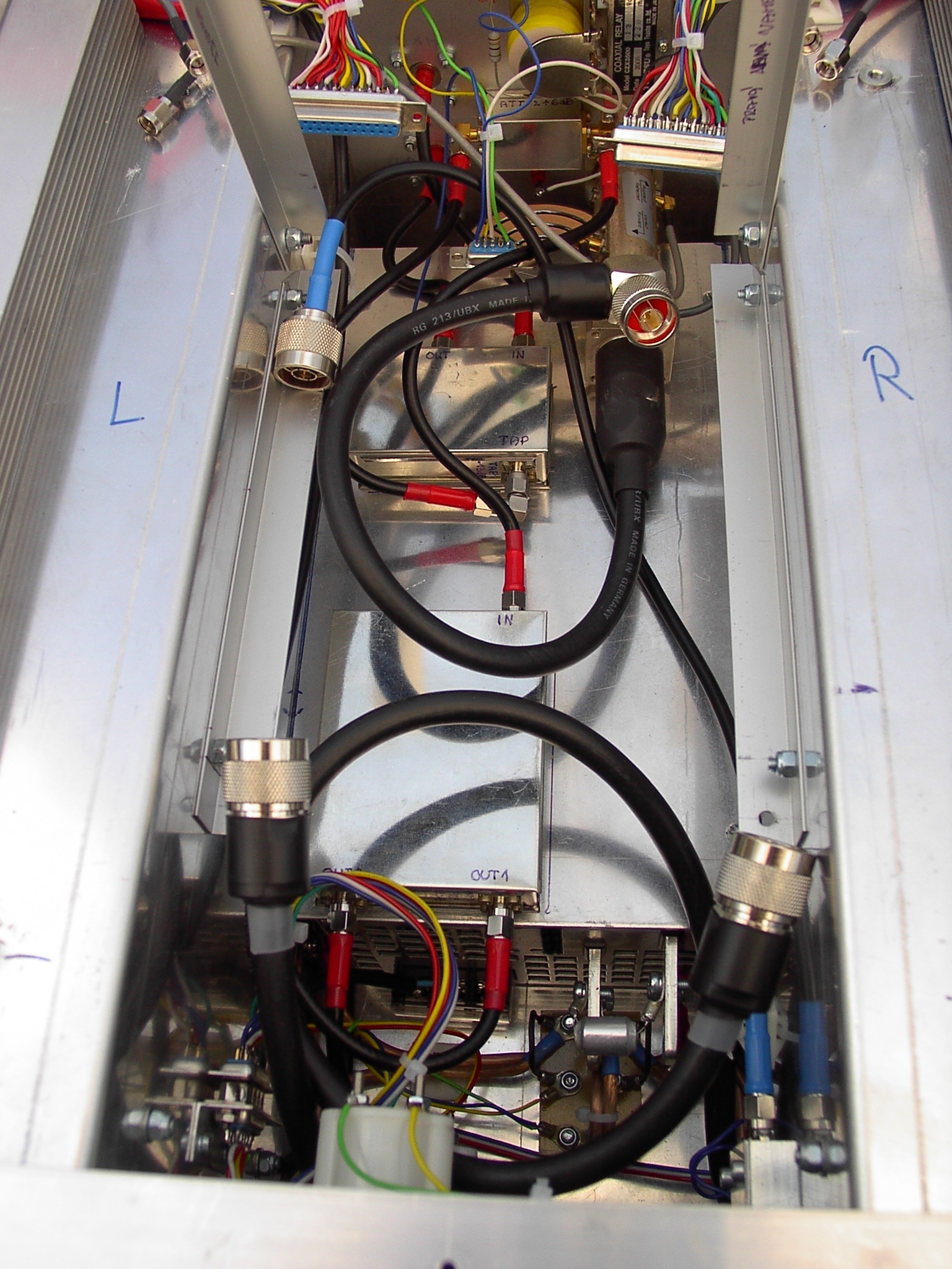
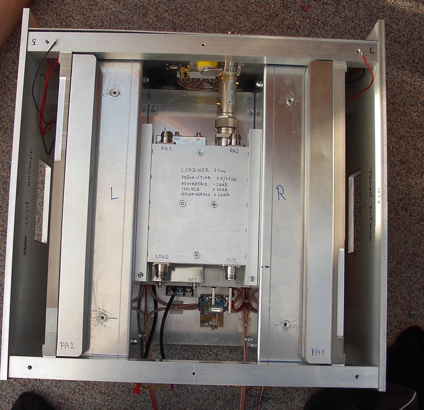
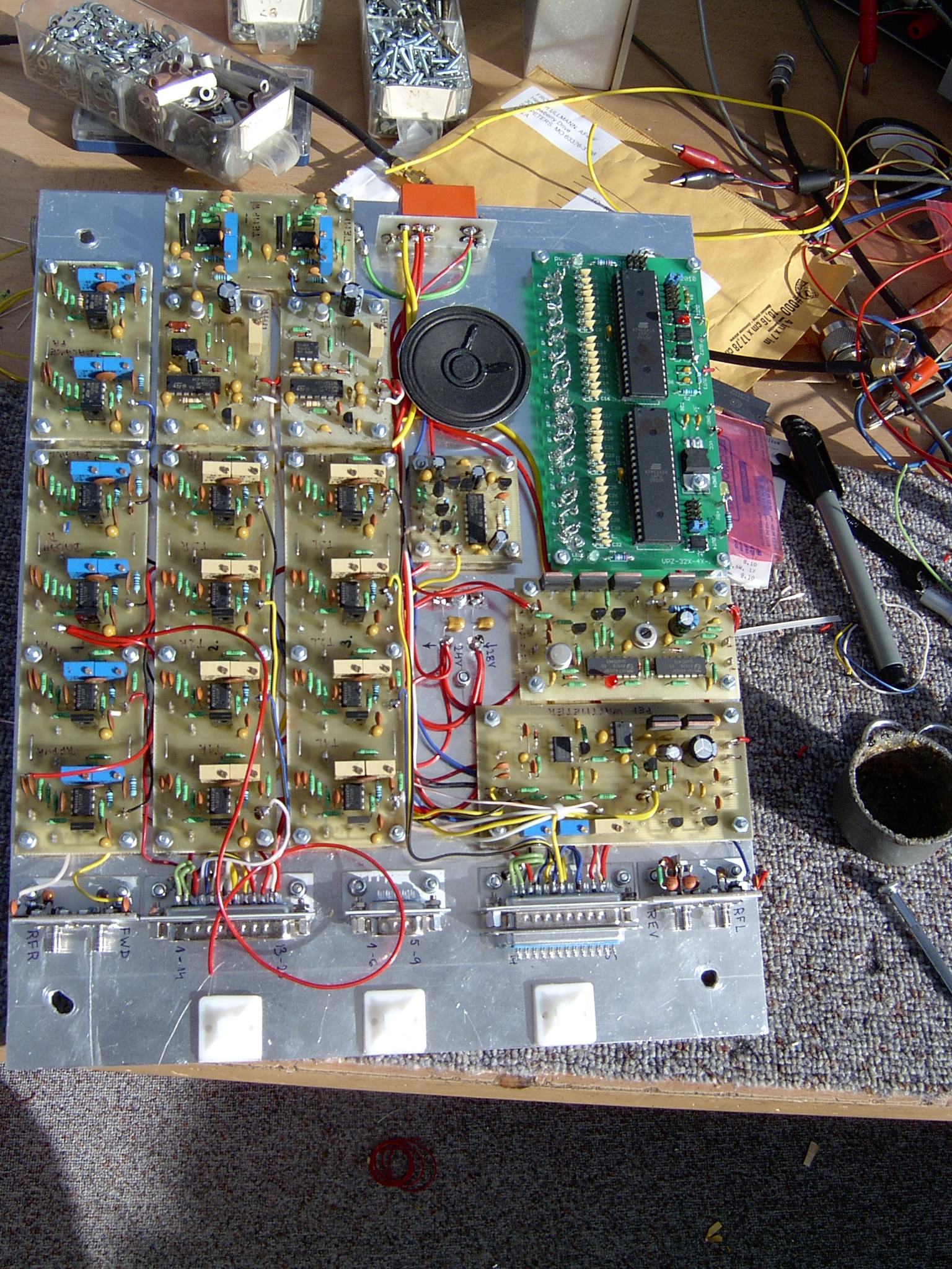
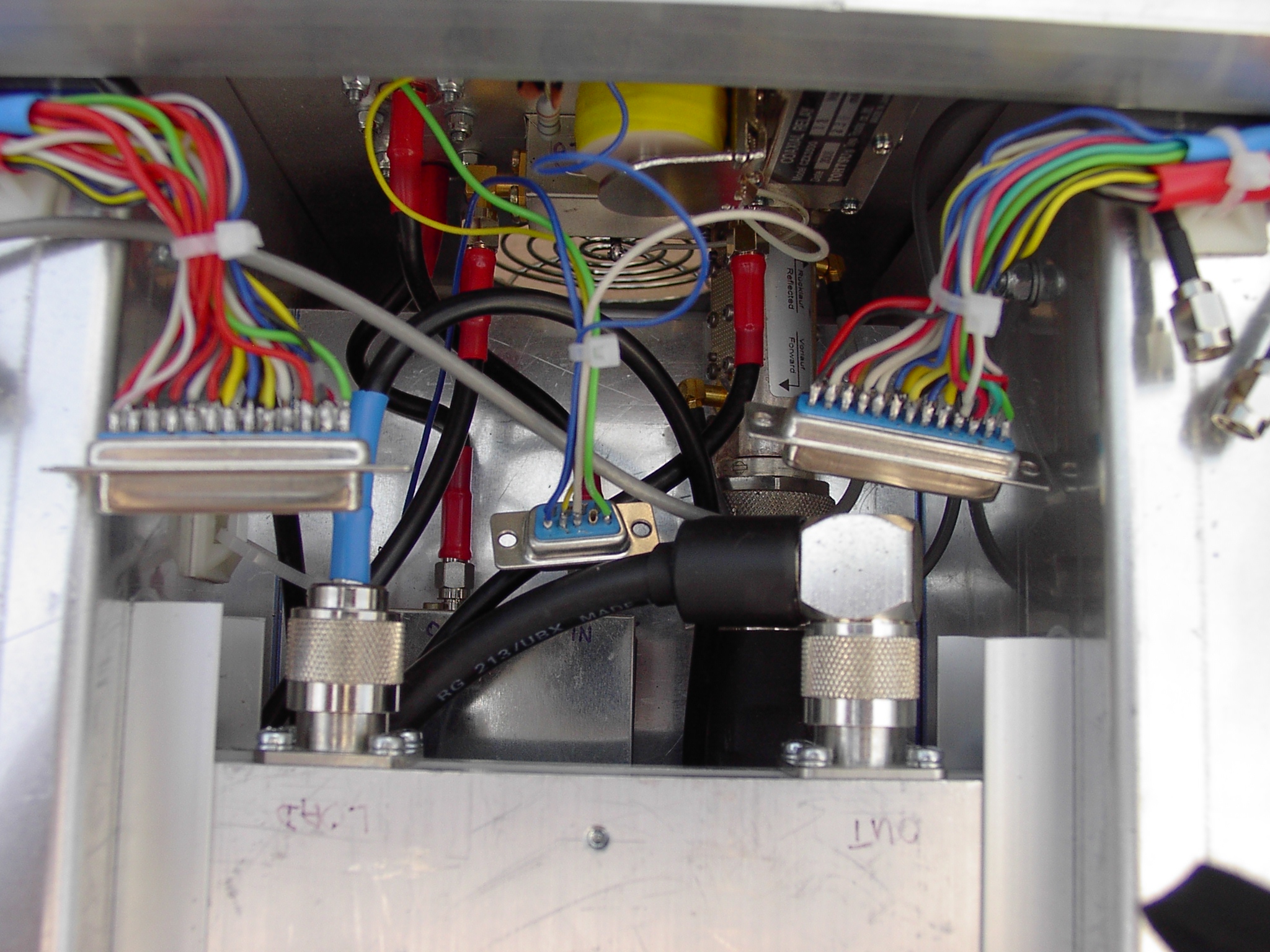
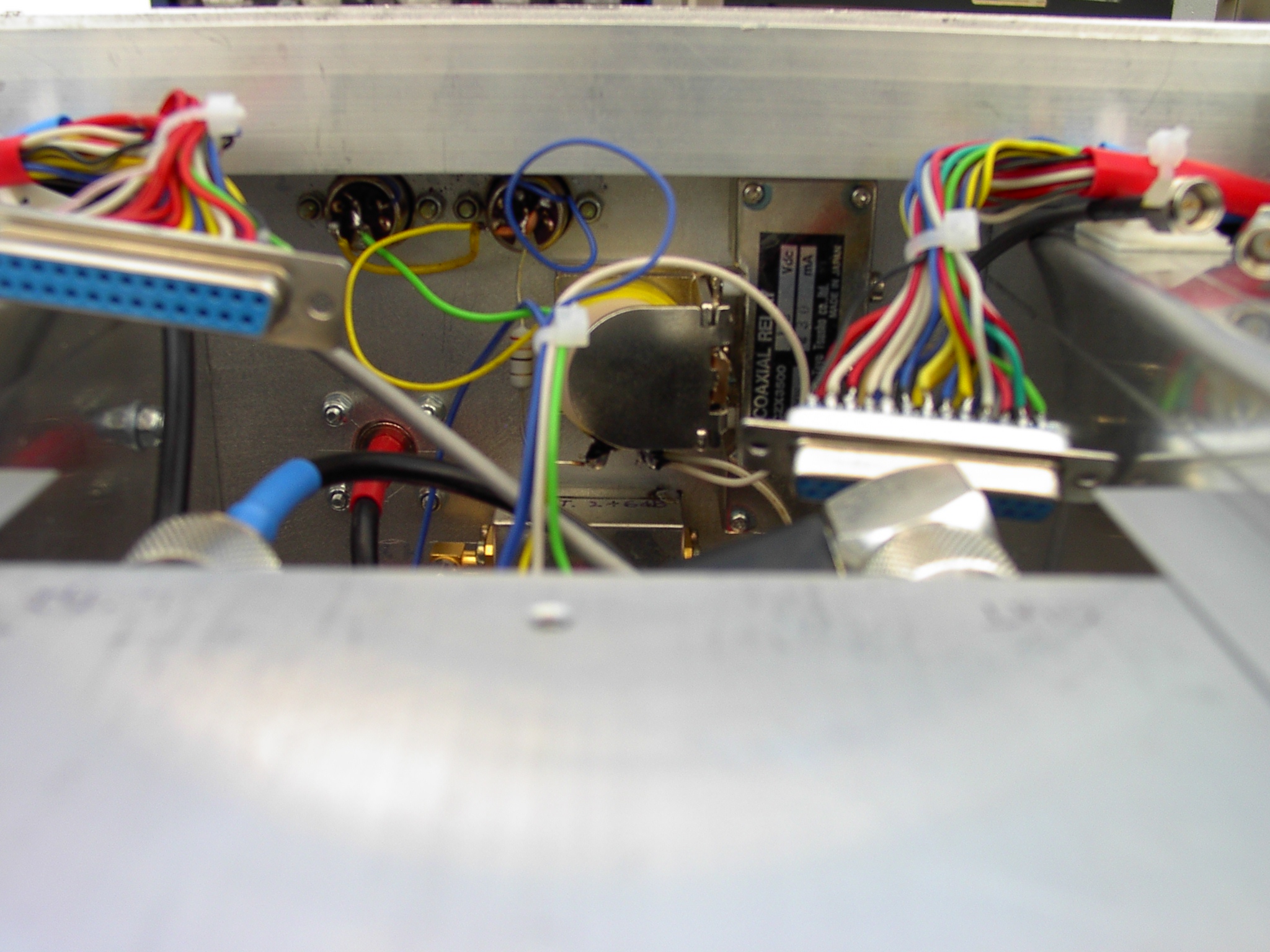
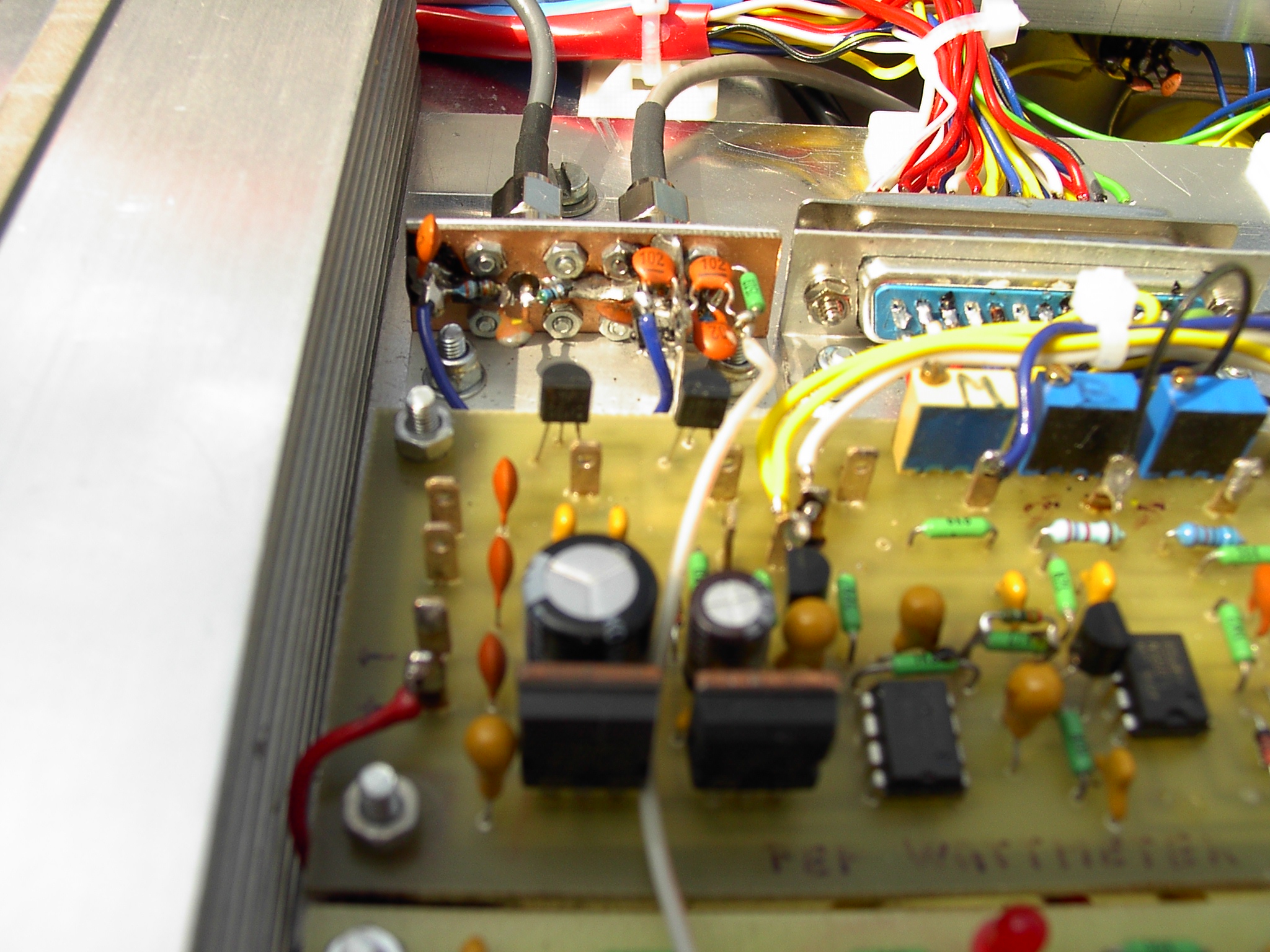
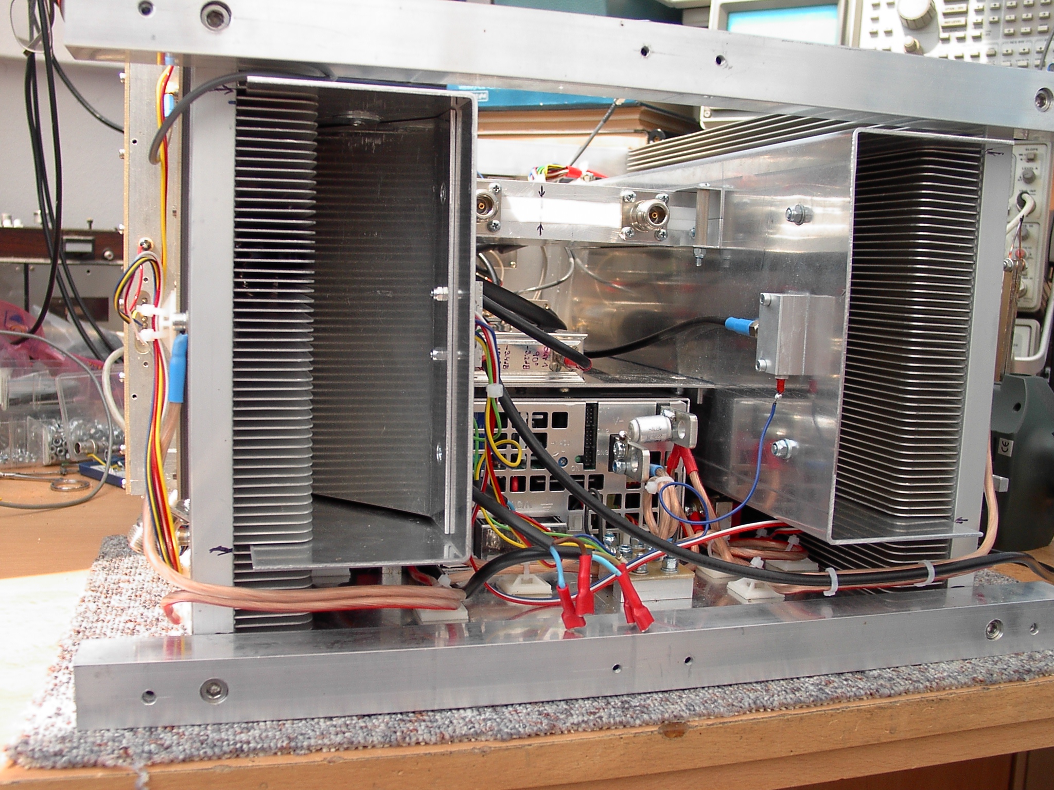
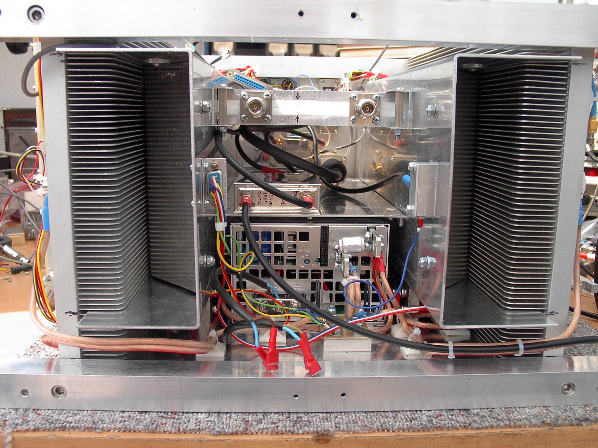
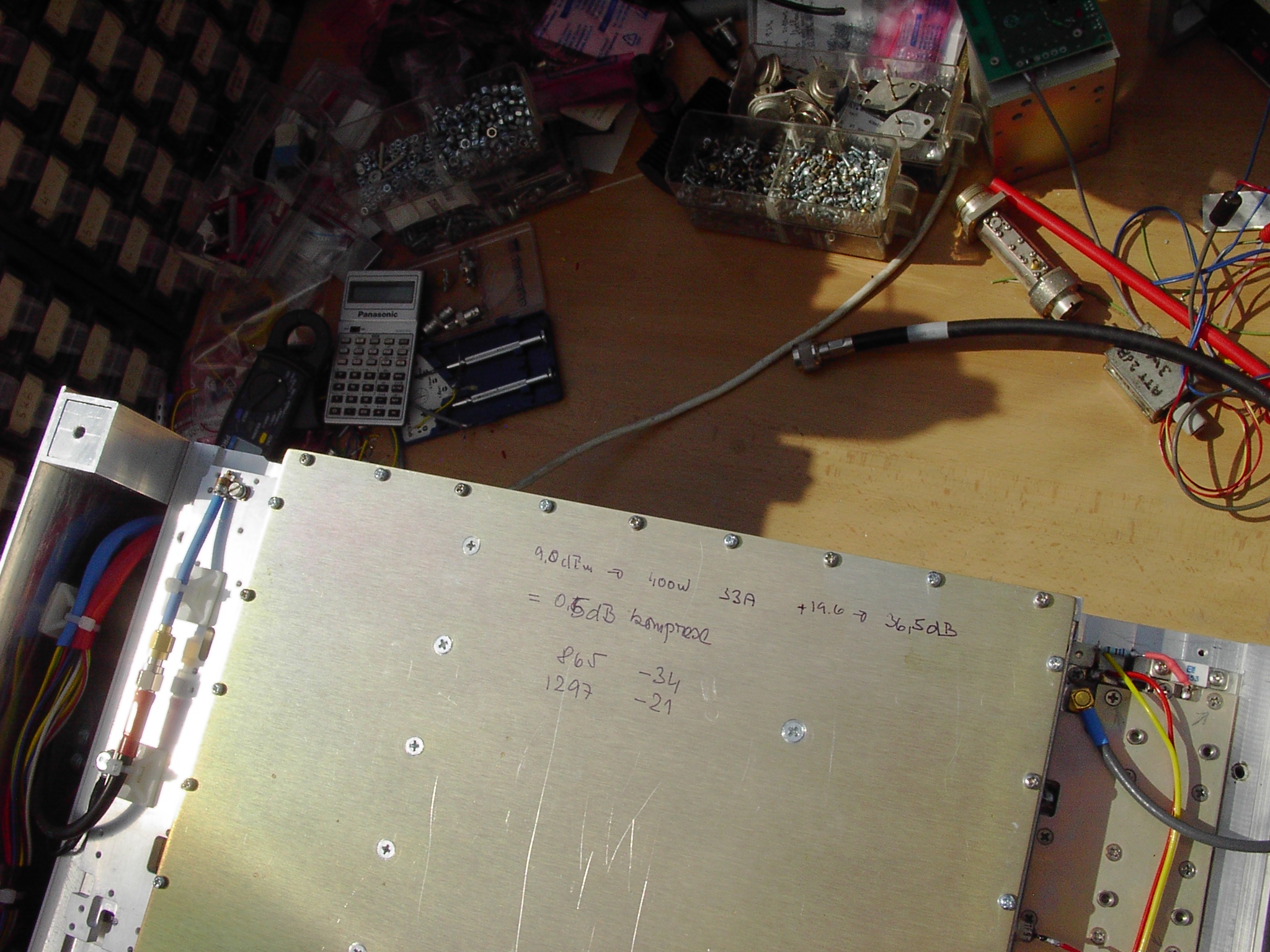
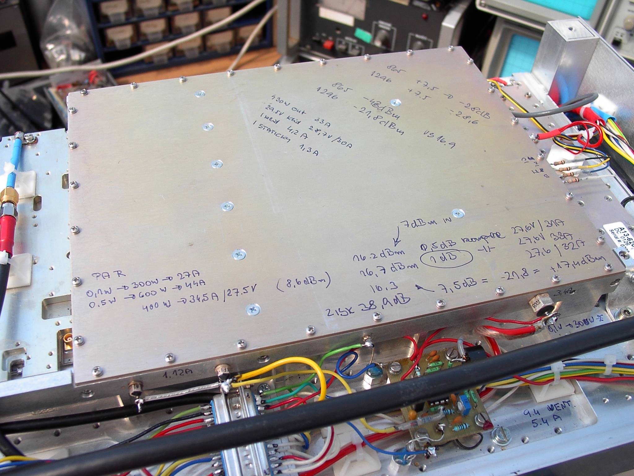
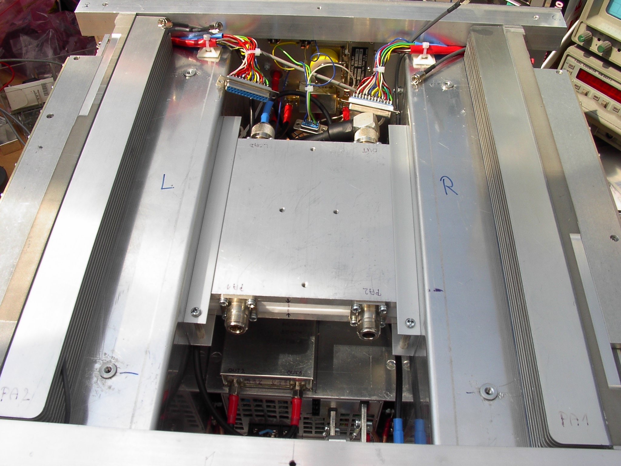
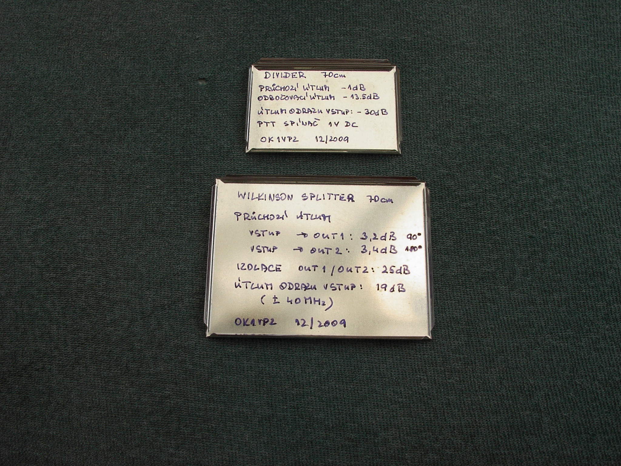
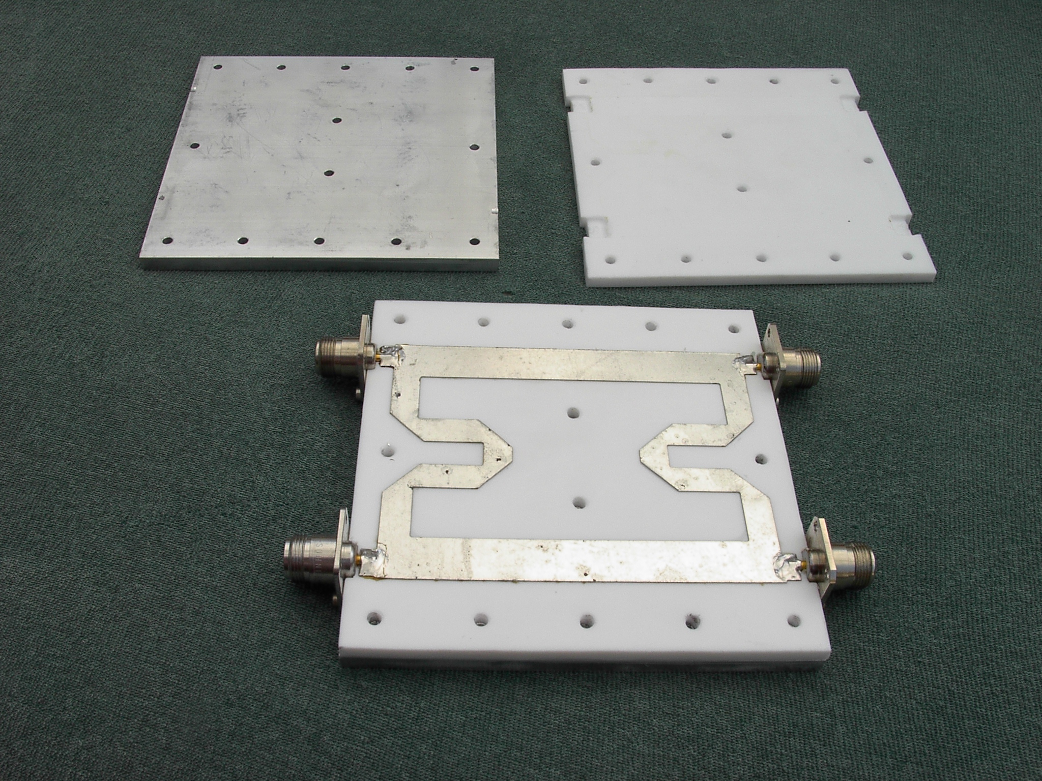
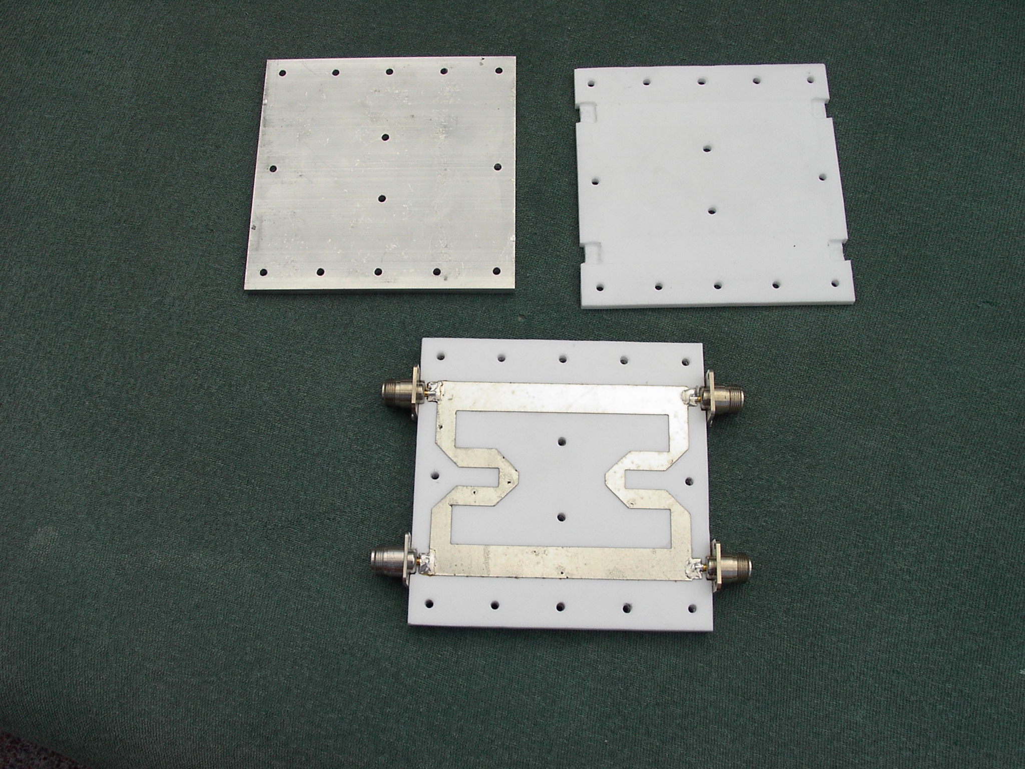
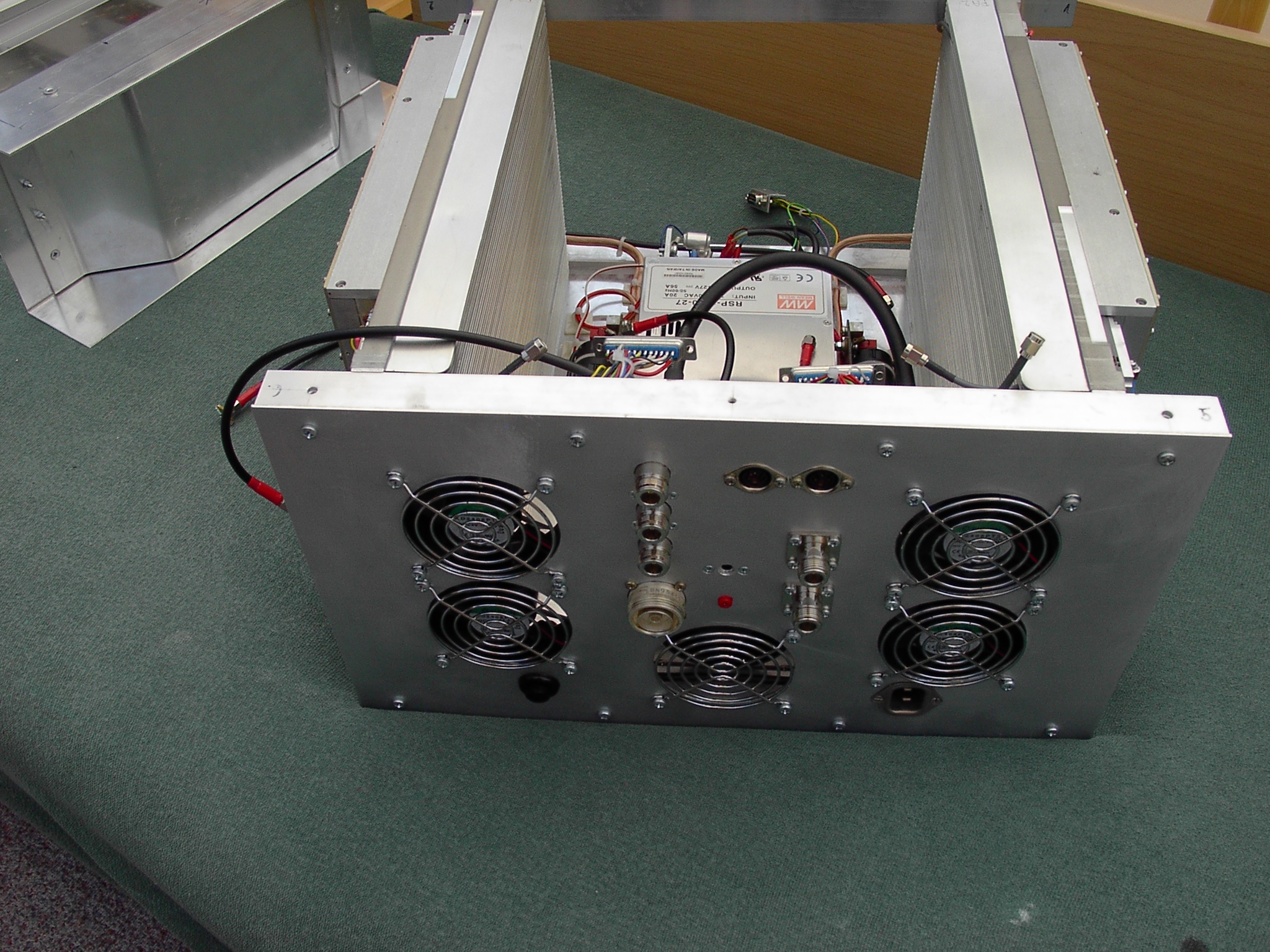
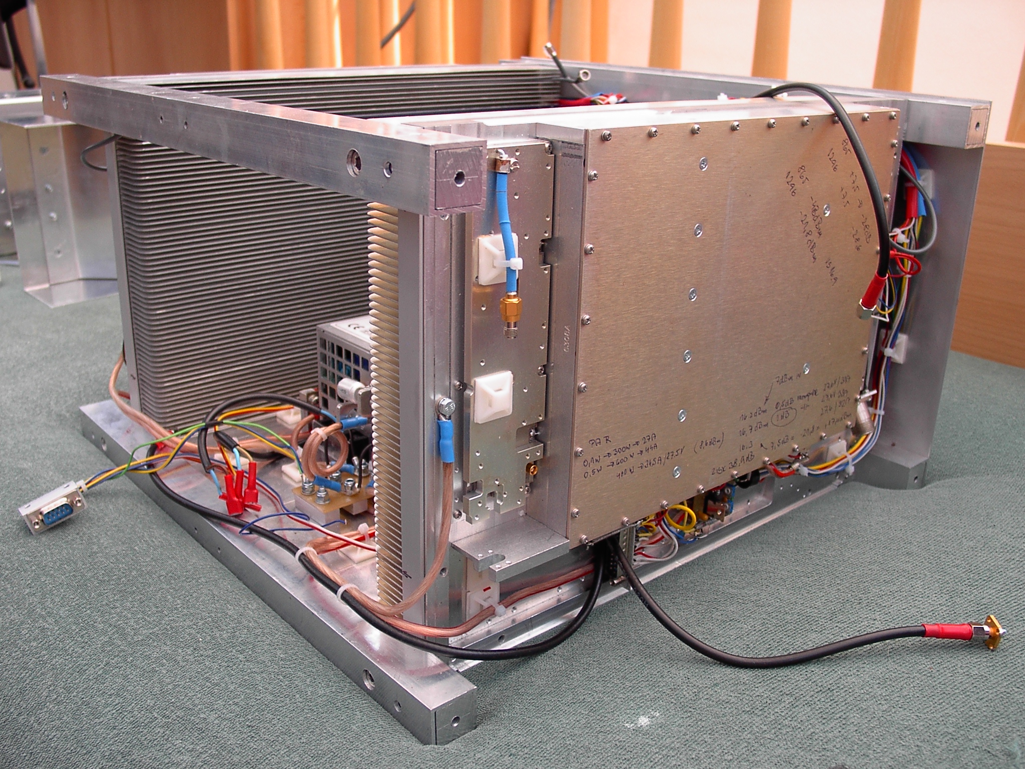
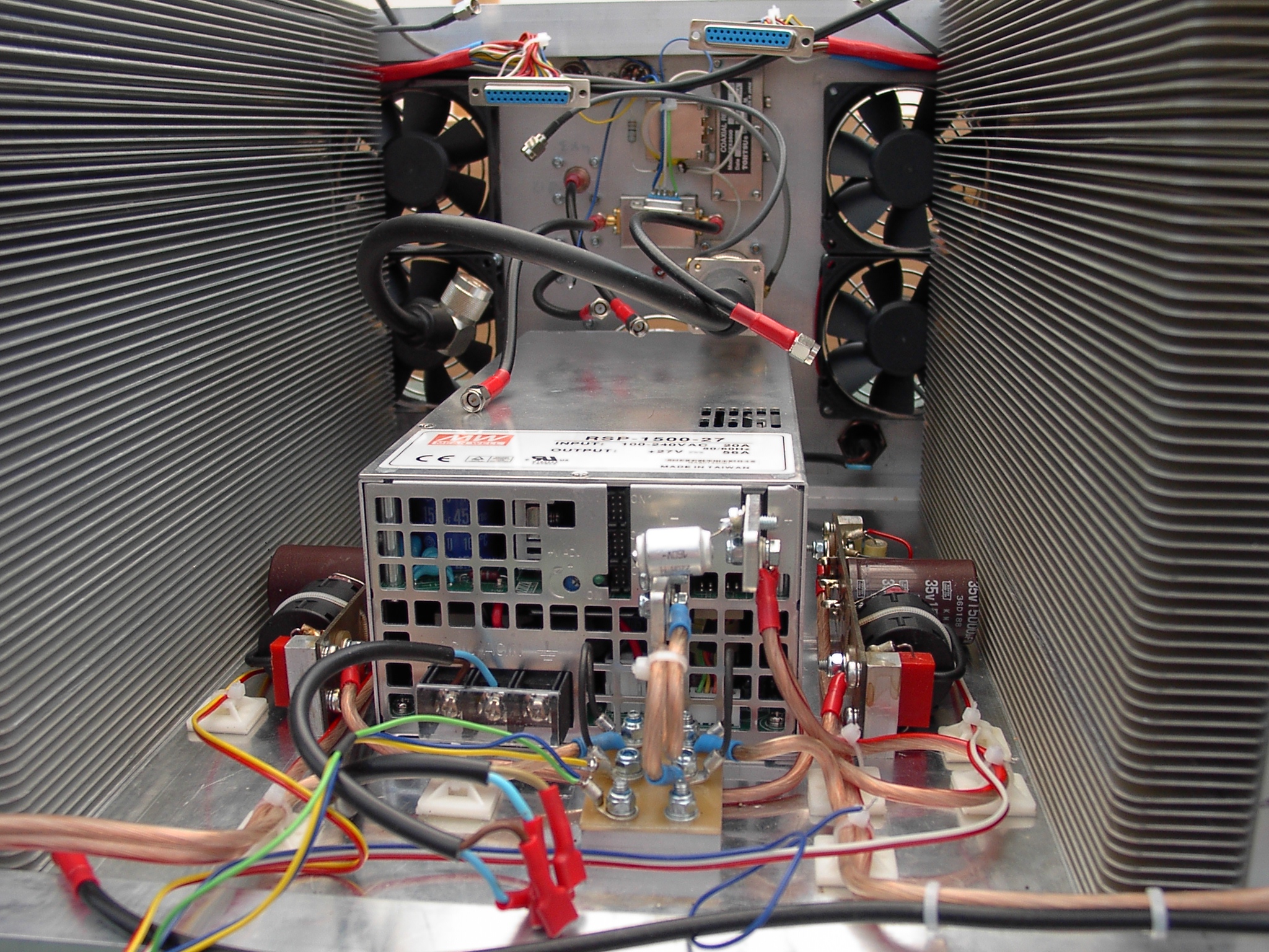
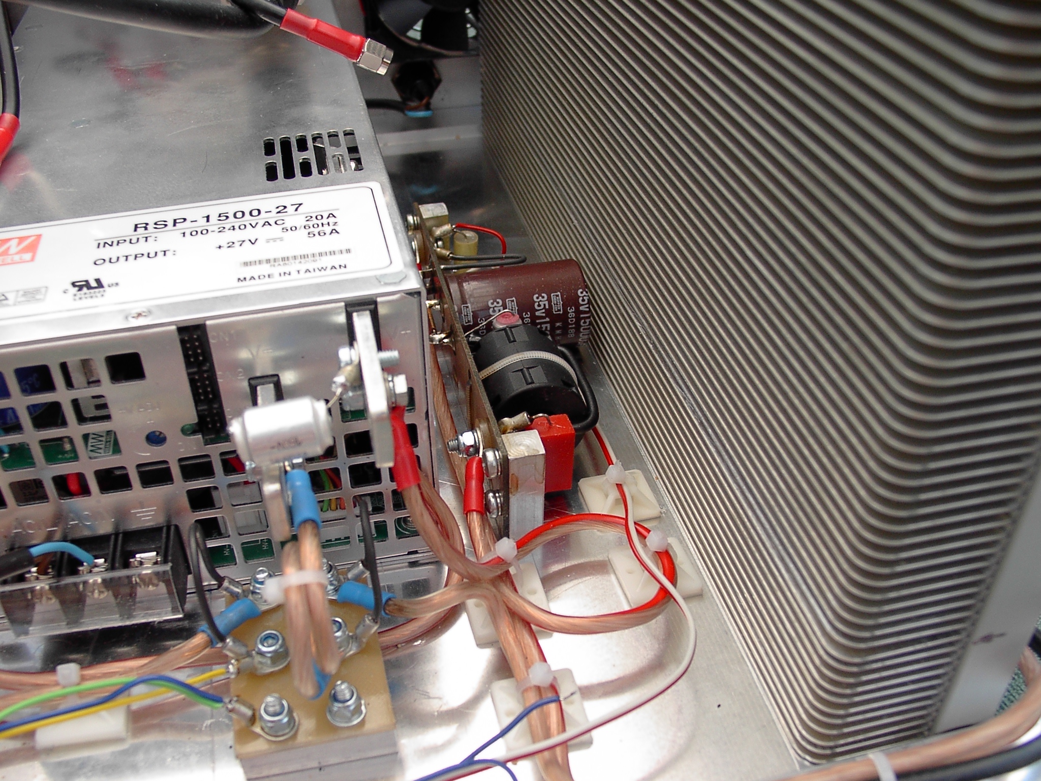
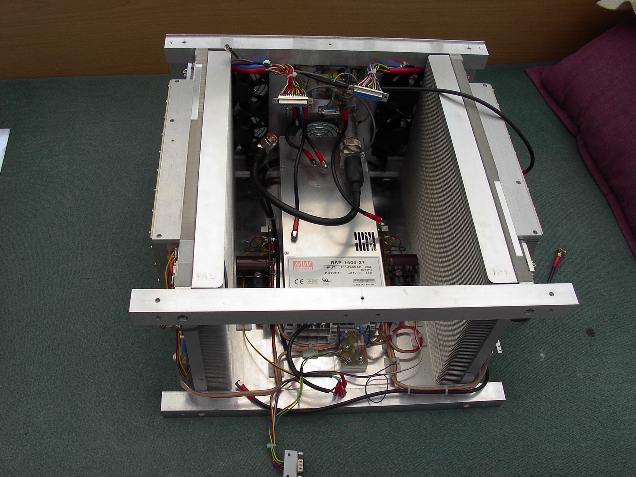
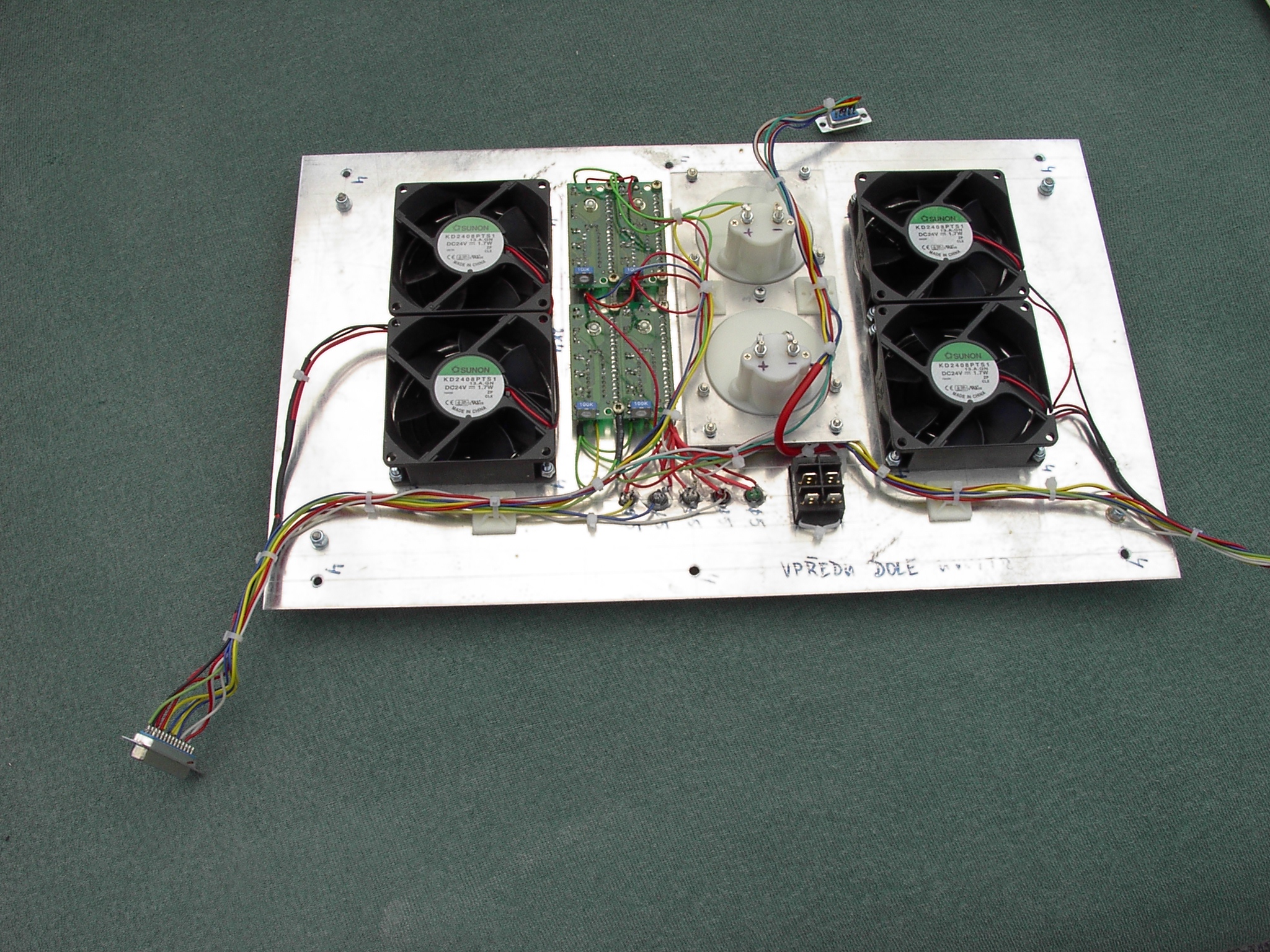
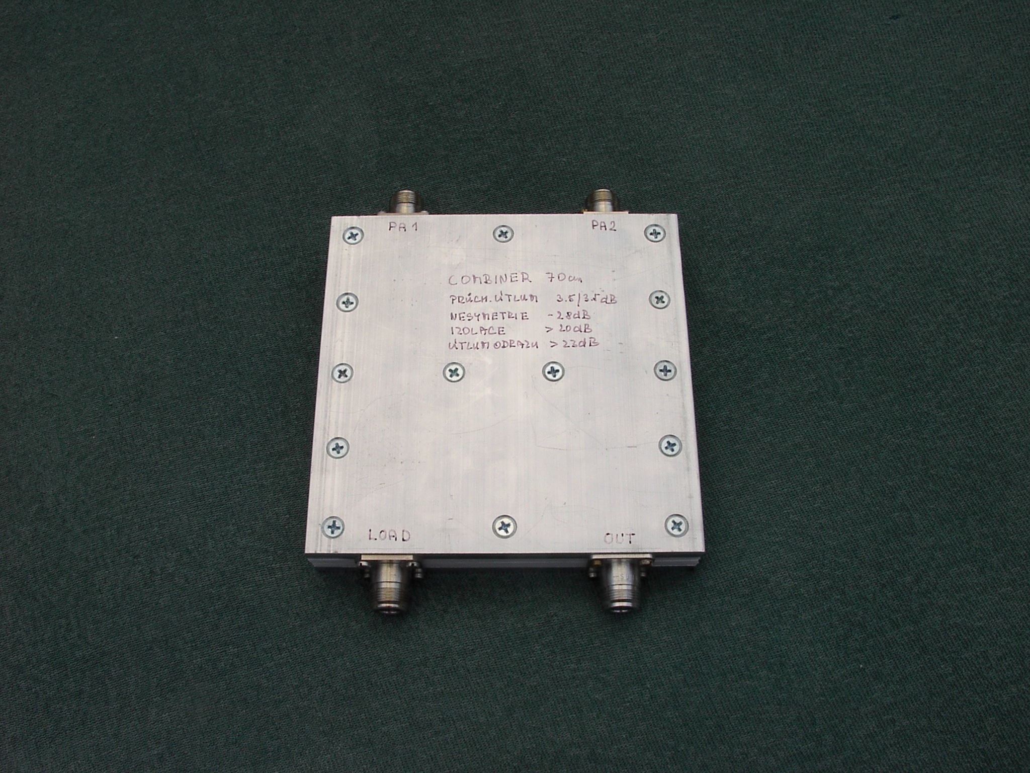
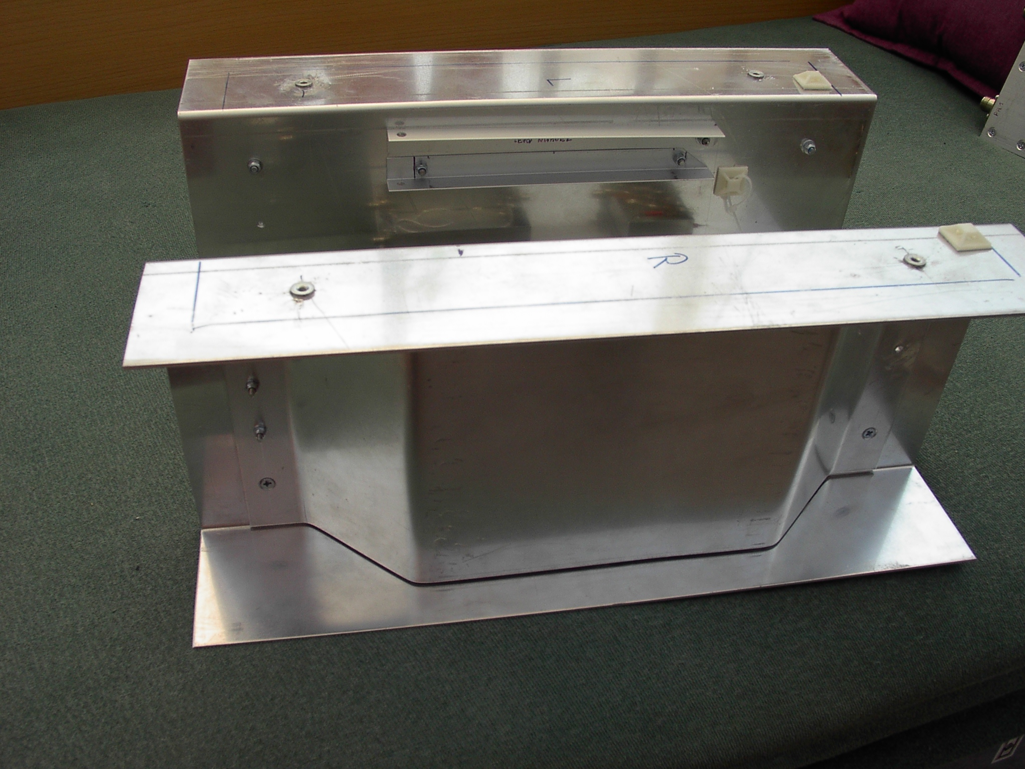
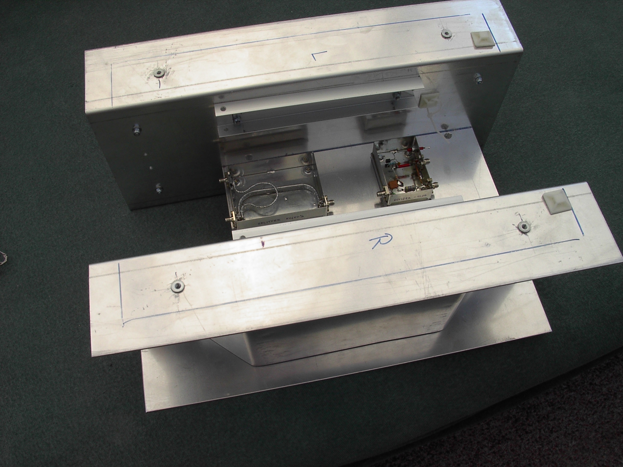
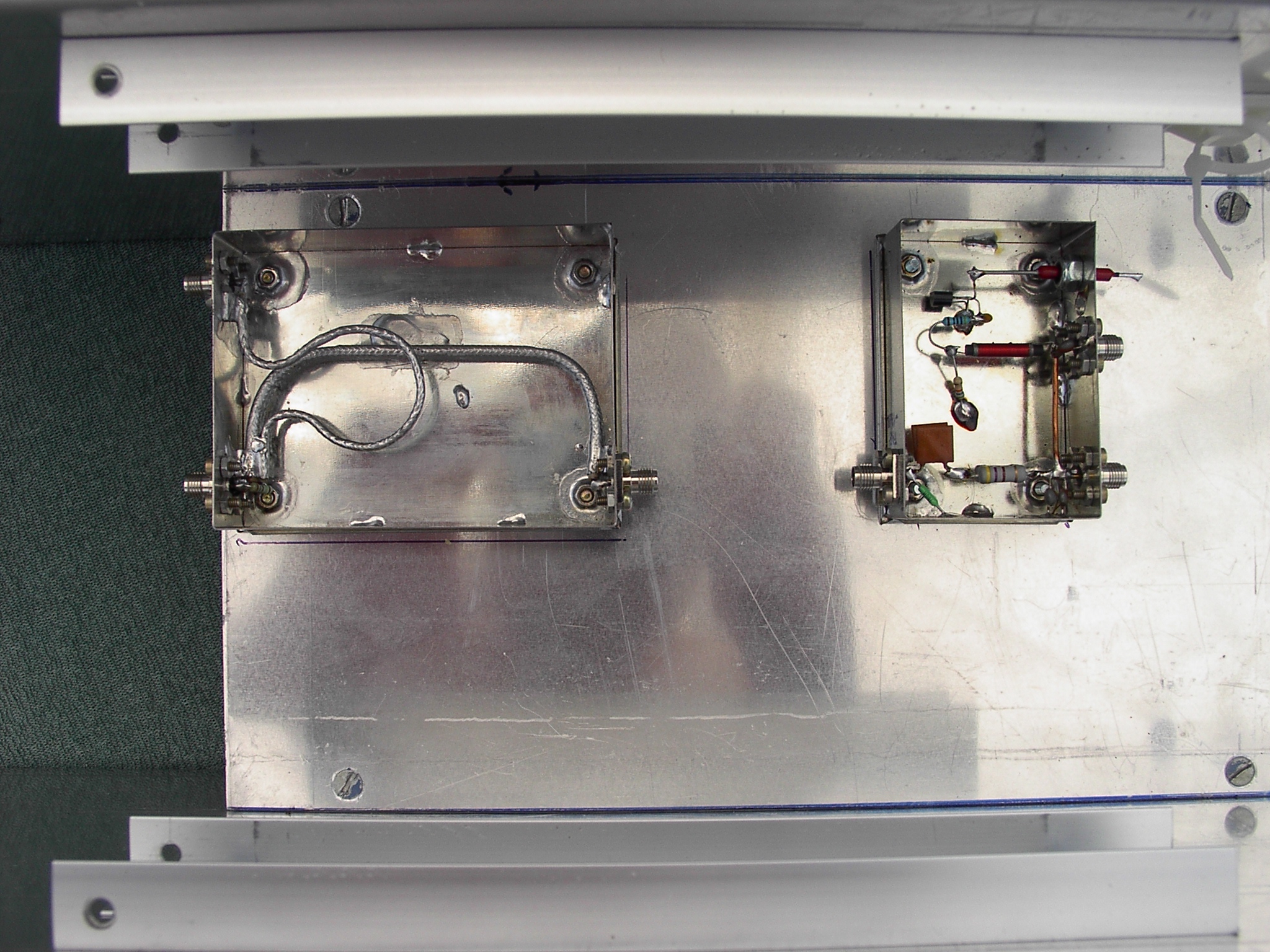
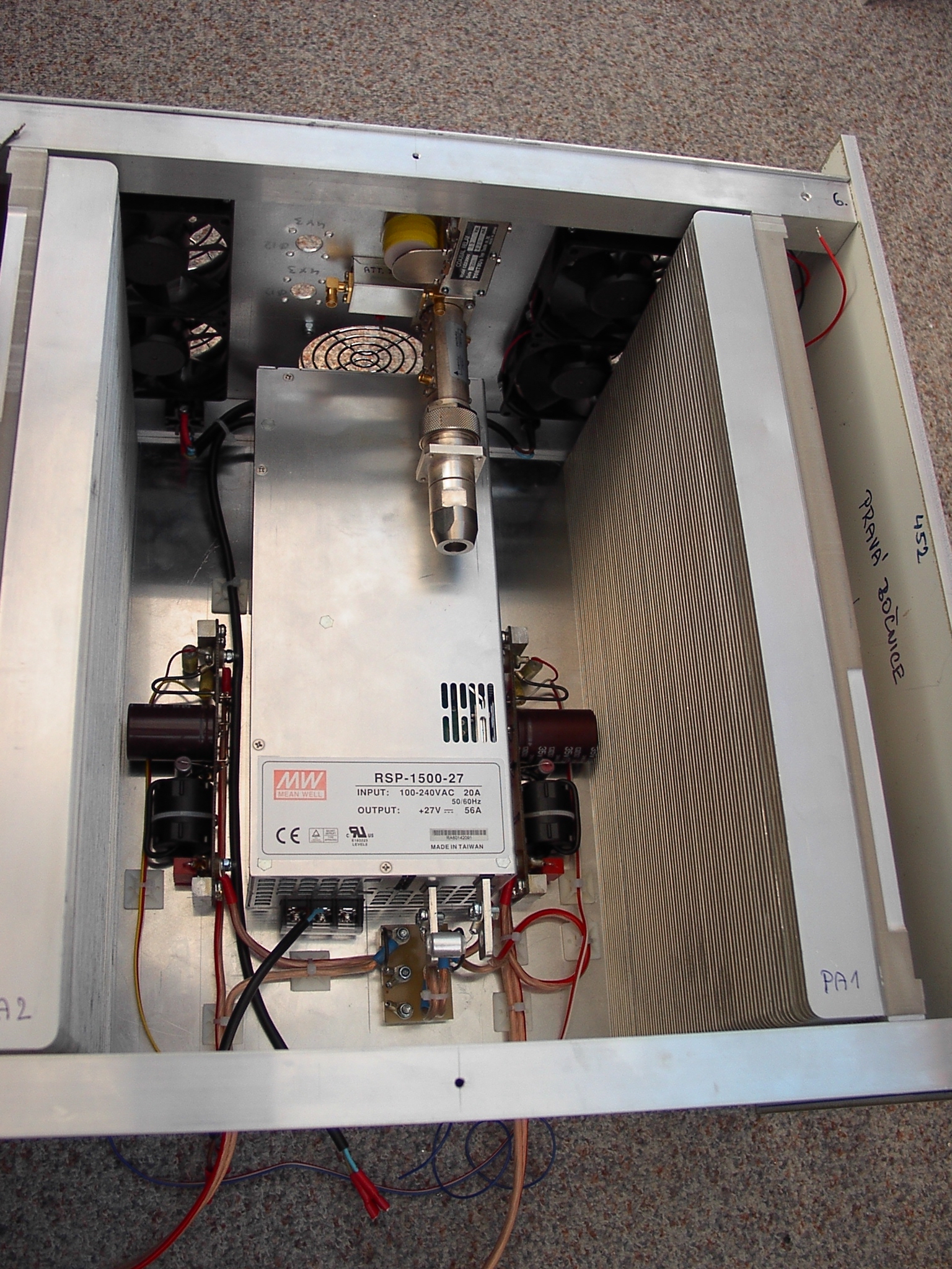
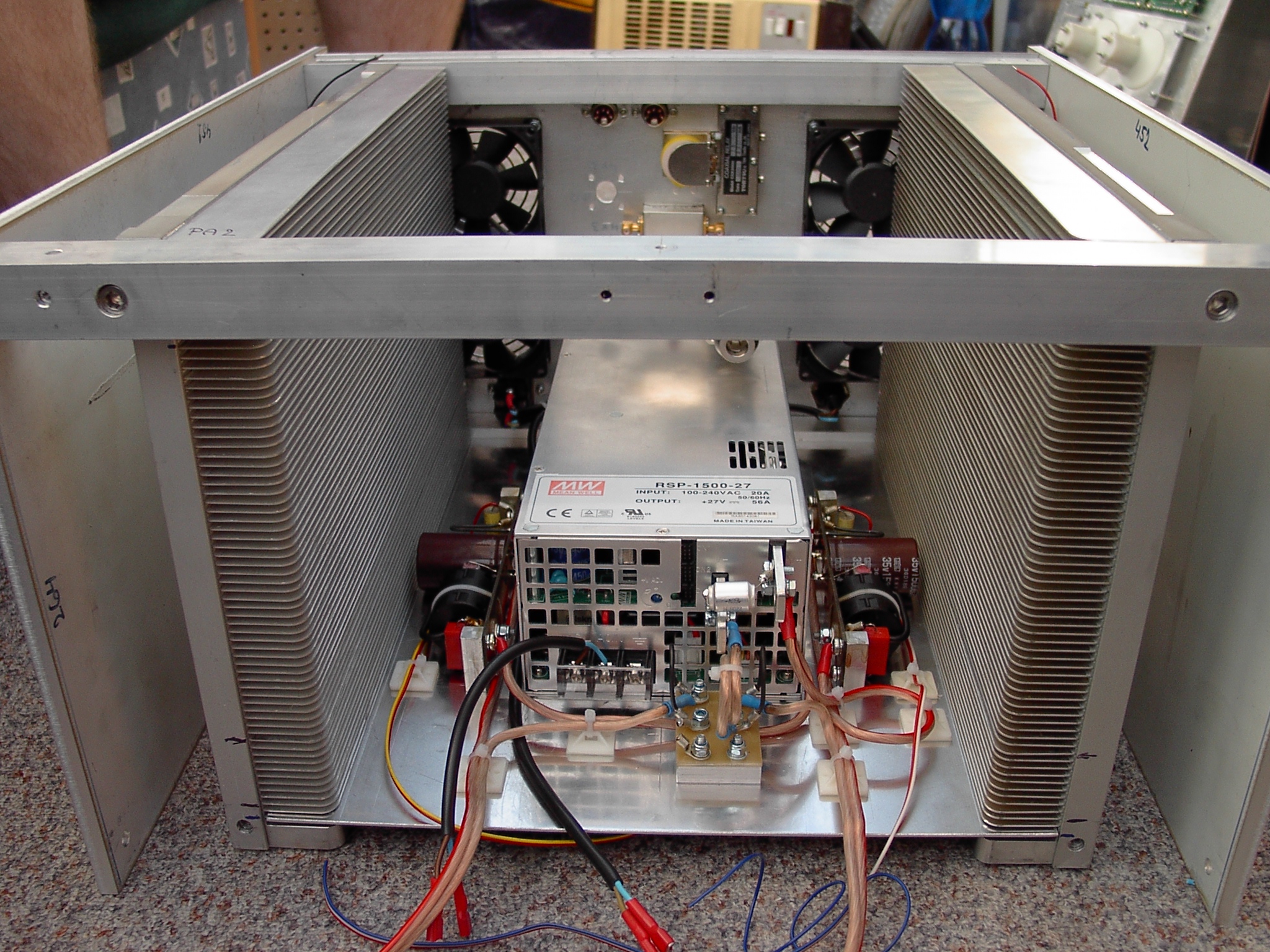
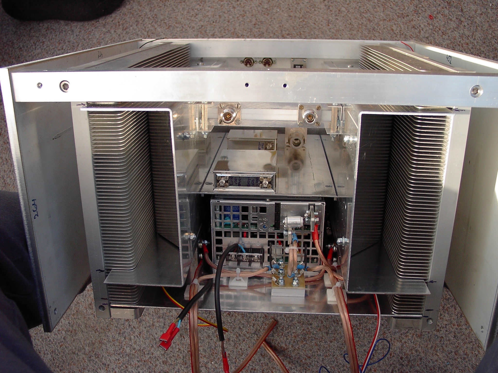
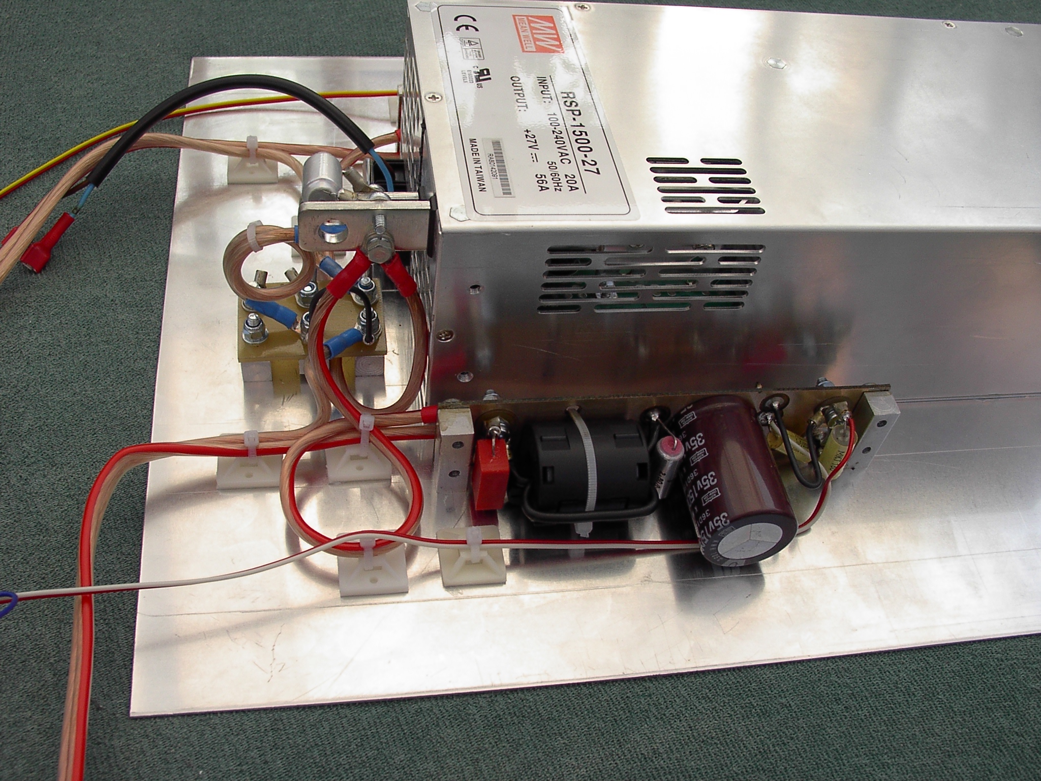
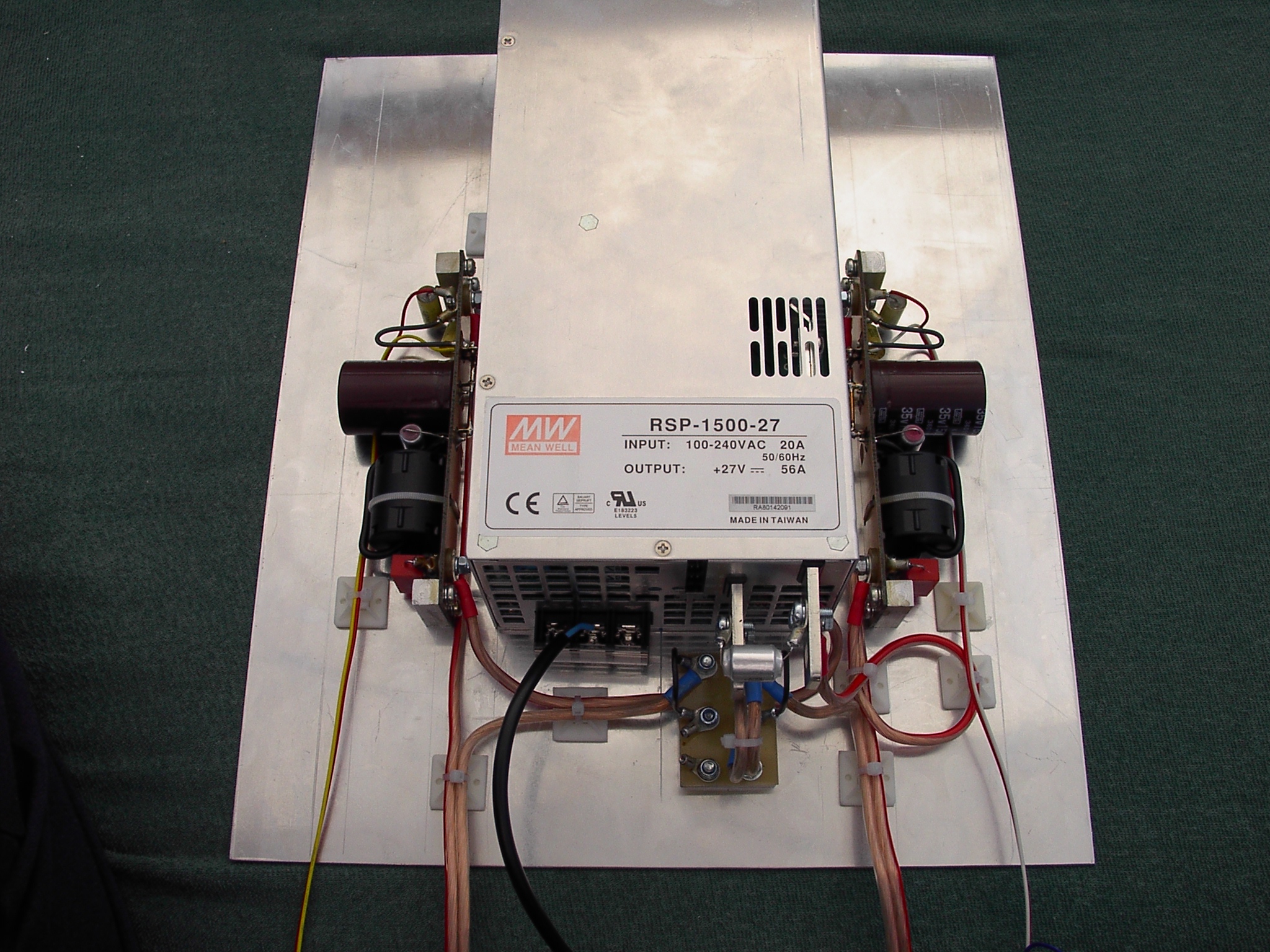
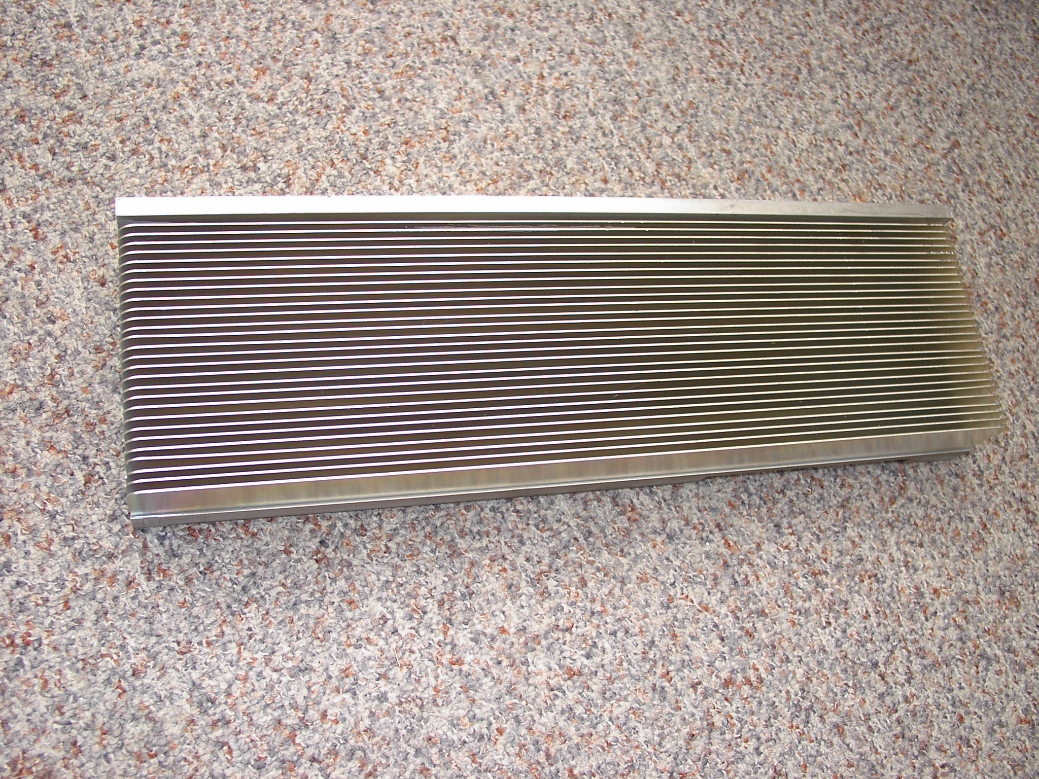
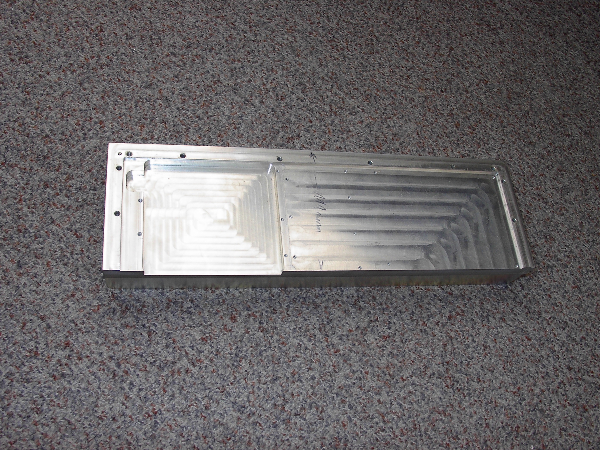
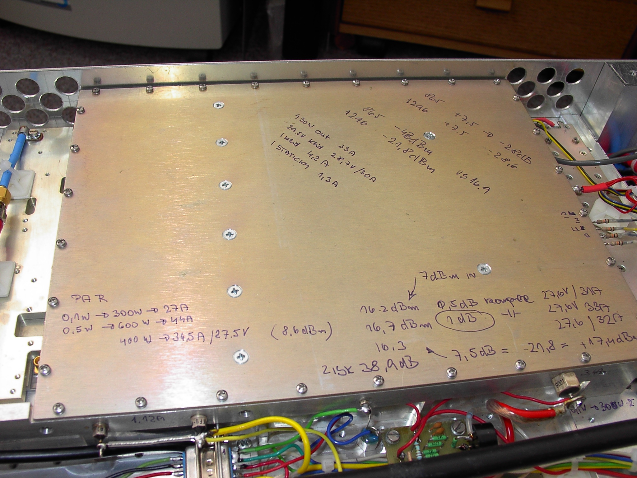
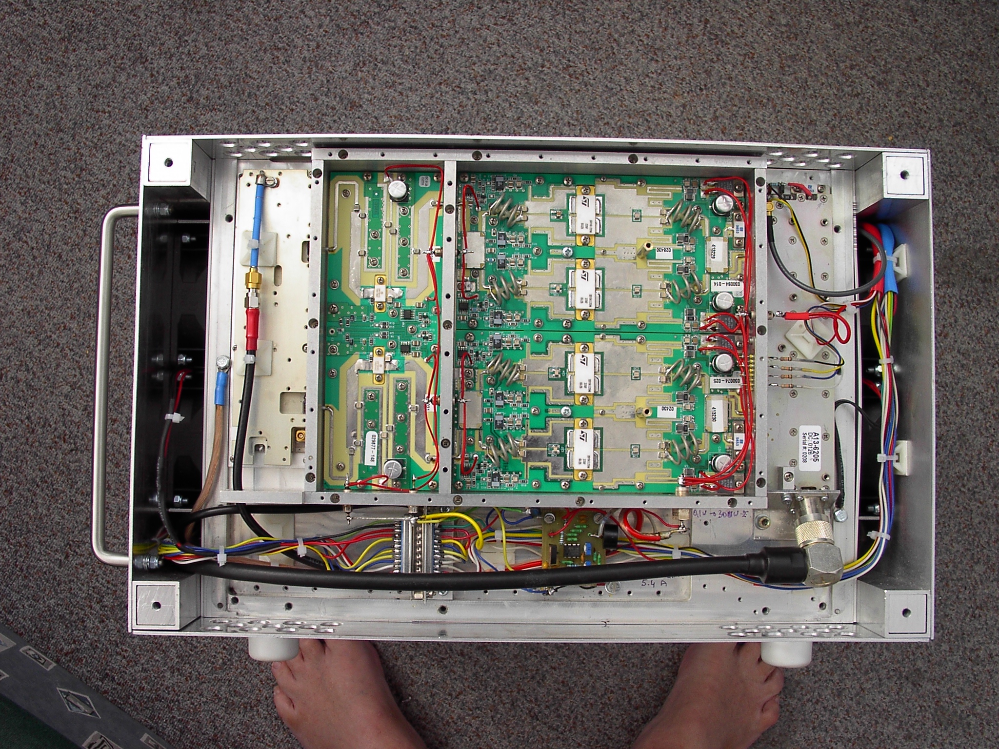
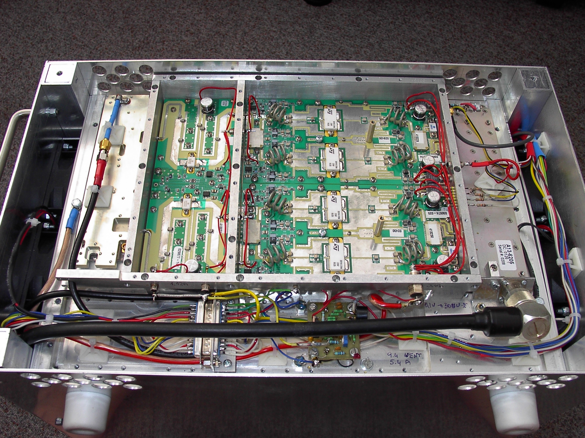
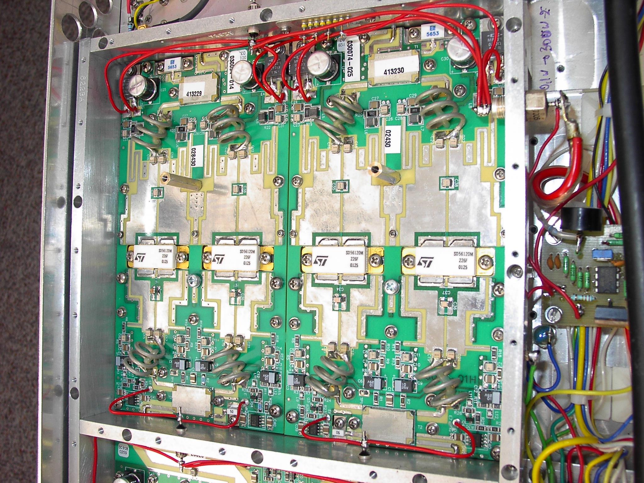
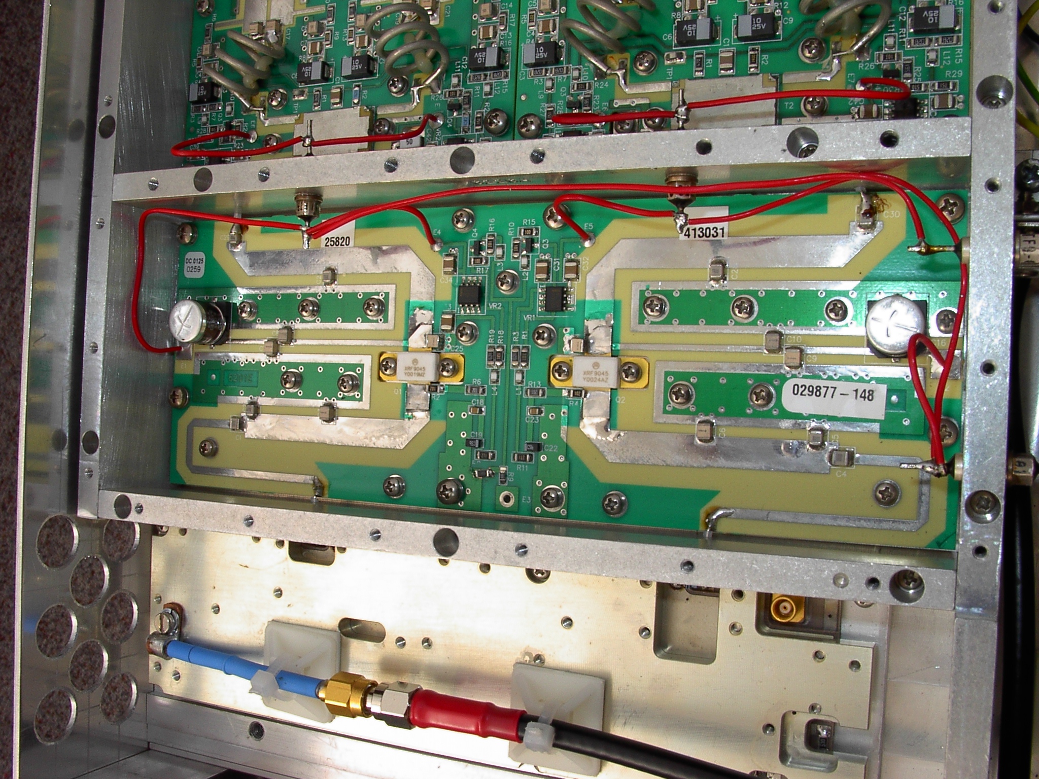
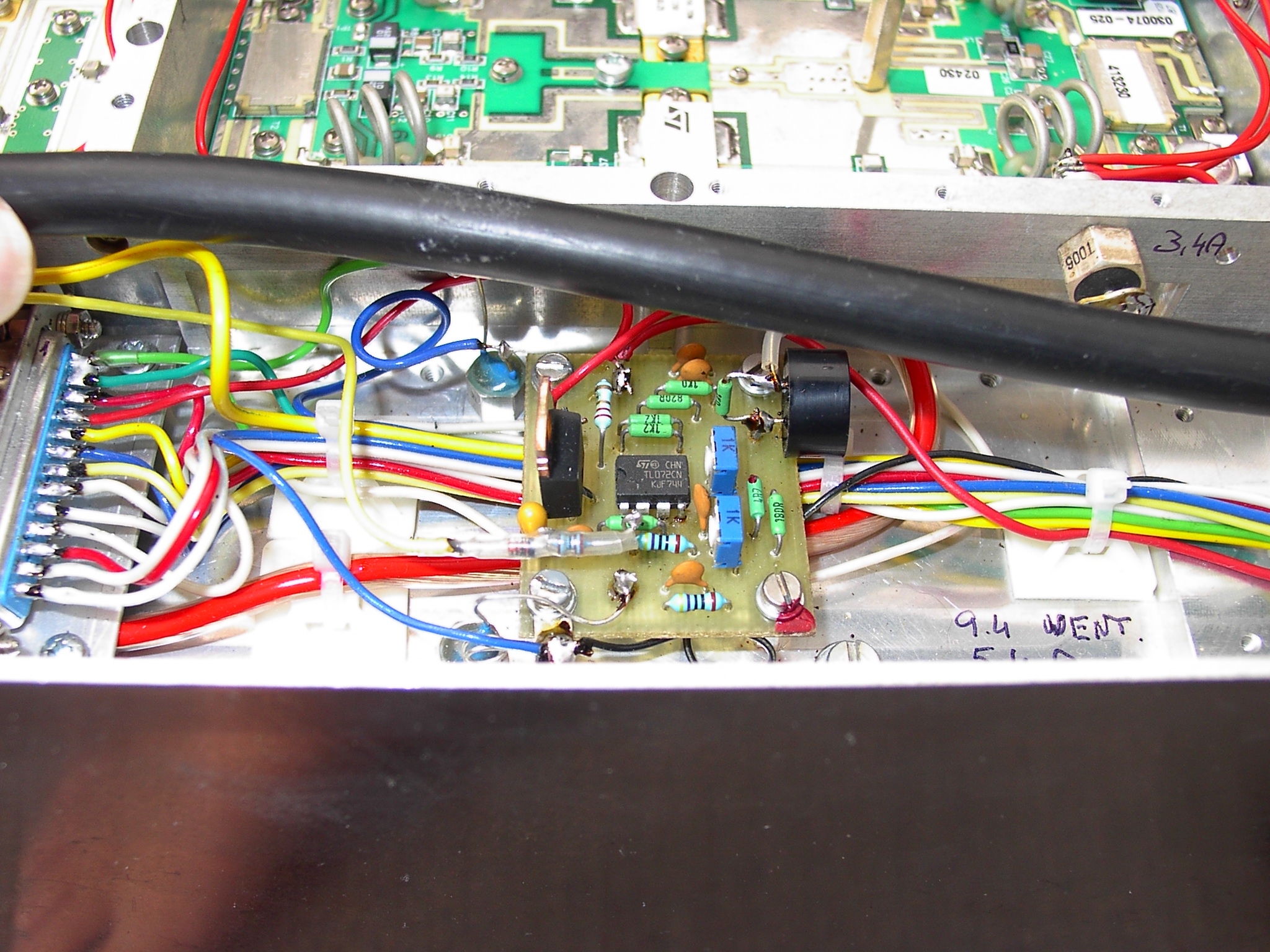
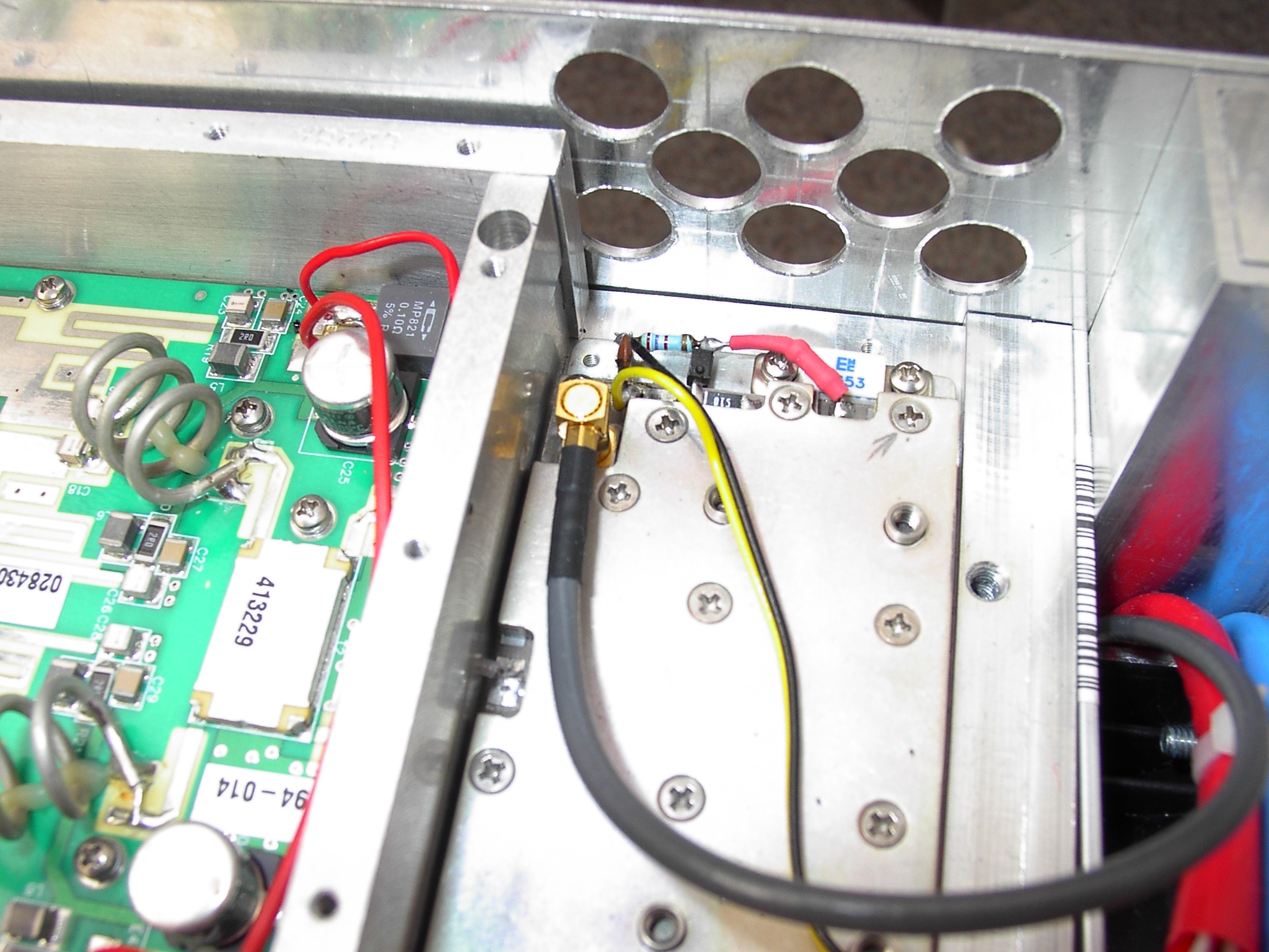
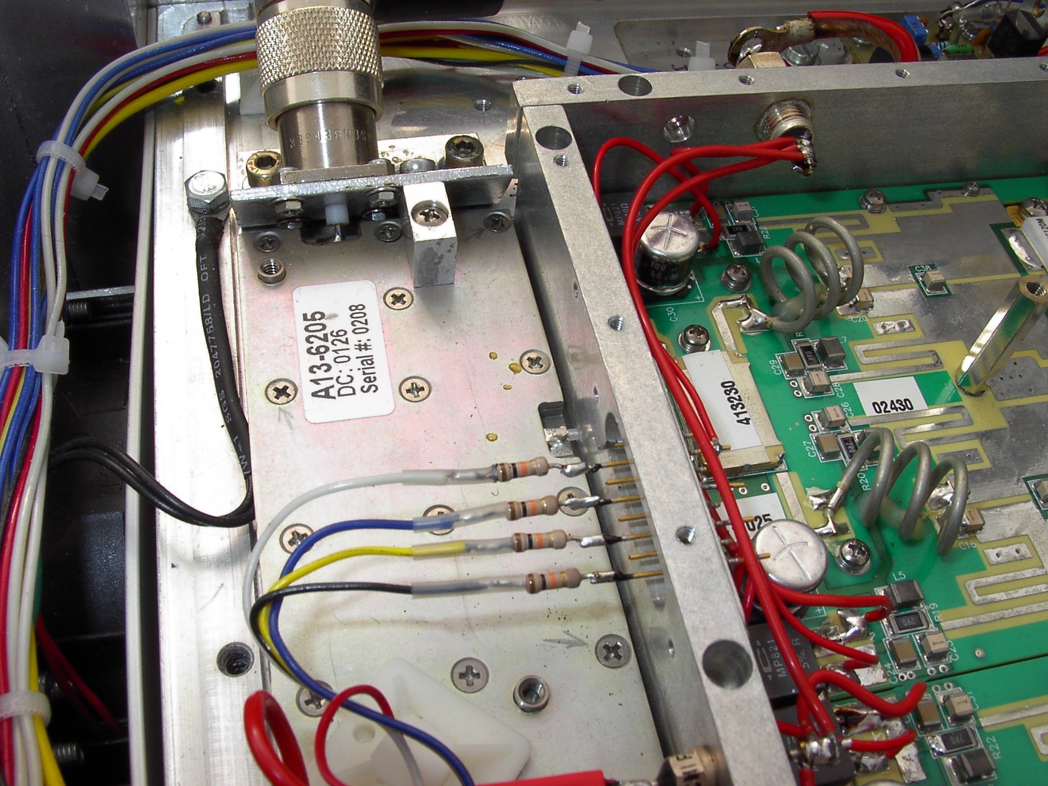
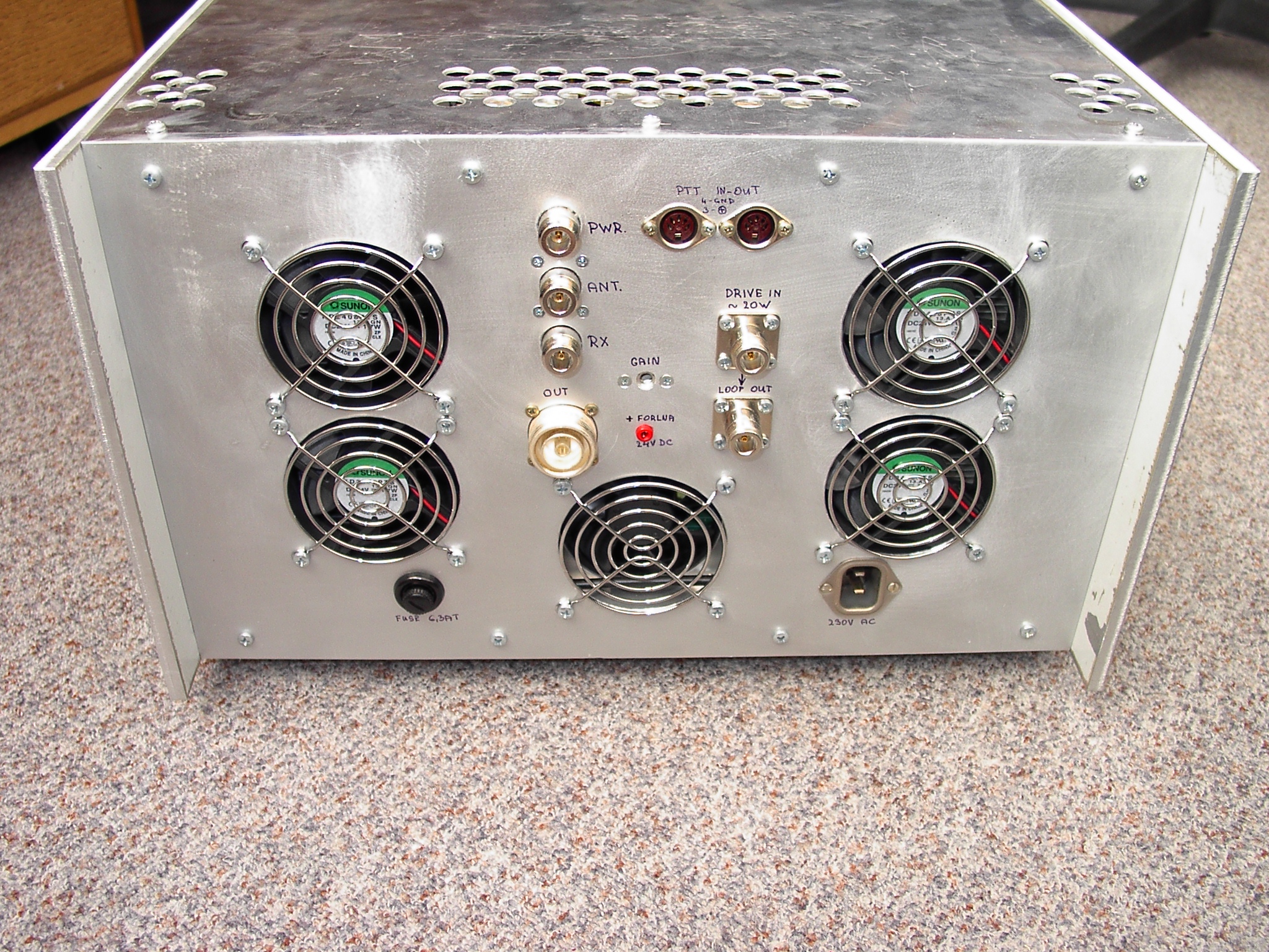
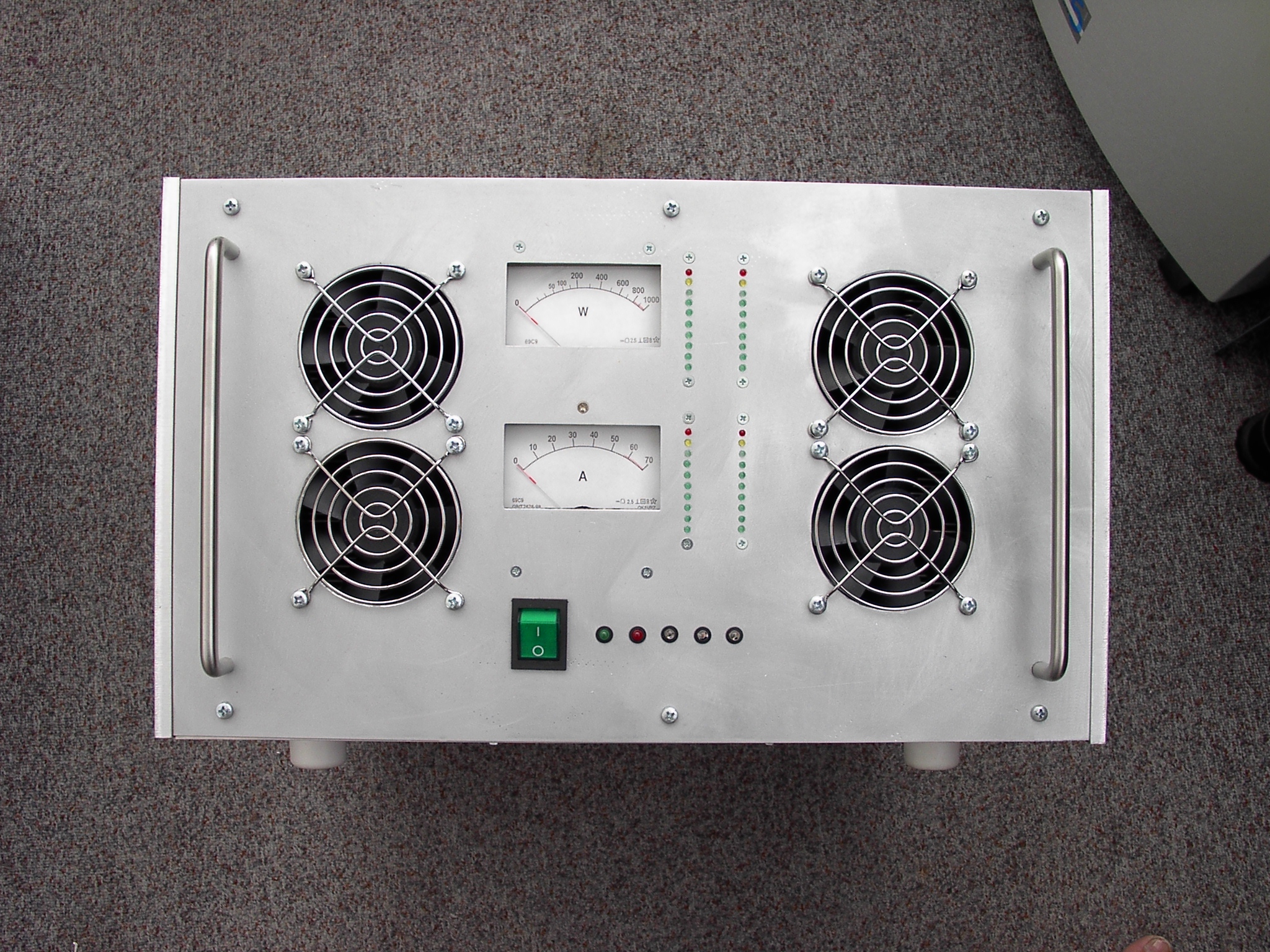
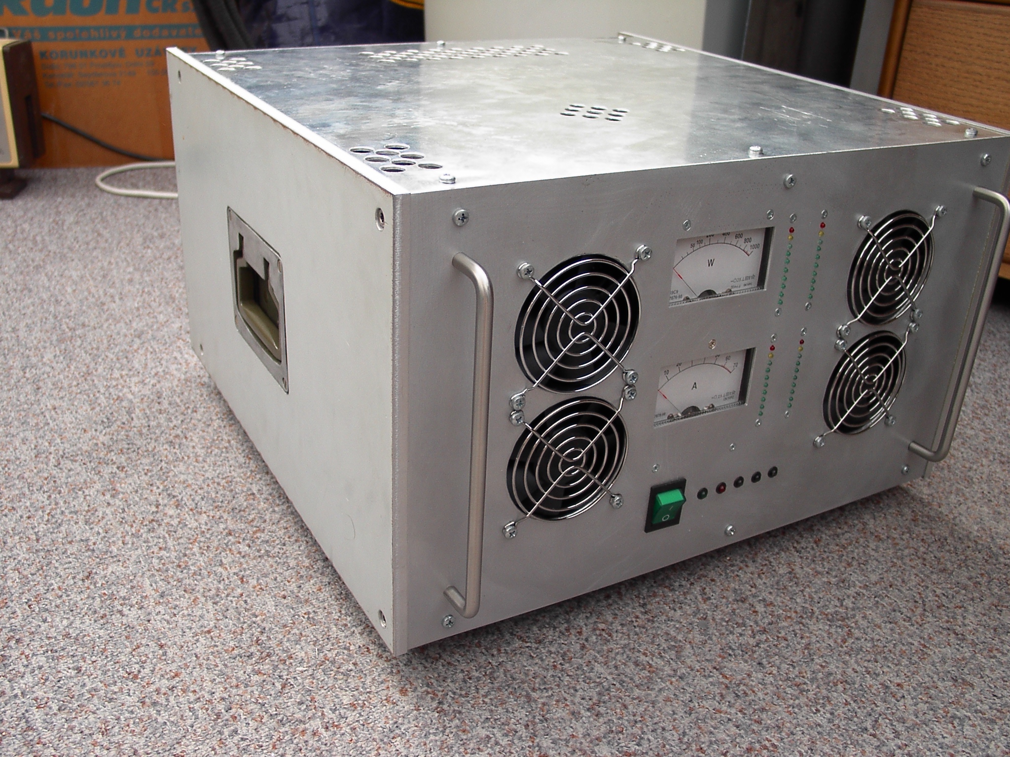
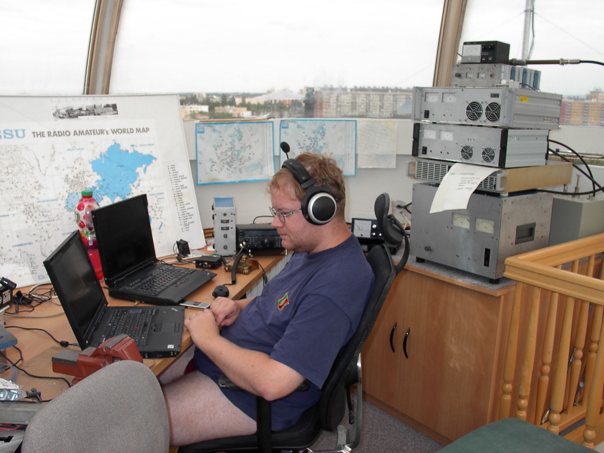
July report from Czech Field day VHF Contest 2010 remind our new solid state PA for 70cm. Although this PA design is quite ordinary, readers of OK2KKW web maybe will consider some photos and a brief commentary about it's construction as an inspiration. The PA use two surplus 400W solid state blocks, bought in Poland, probably available from upgrade of some US cell phone Base Stations. The US cell phone network operates around 450 MHz and one of these module was used in very reliable telecommunication mode for max 100W out. However the module based on four double SD56120M transistors and driver stage by two XRF9045 may deliver (based on the datasheet) about 480W RF max with no problem to operate as well as on 432MHz. Because the amateur radio operation request specific attenuation of intermodulation products, the PA blocks are operated up to 400W output limit only, when the IP3 products are about 26dB below PEP. Each PA block consist of two separated PA modules with about 200W out, the input and output are combined with 90° hybrid units consisting of original microstrips on Teflon PCB with thickness of 0,8mm. Please note that these power modules aren't identical, the left and right module differ in layout of components and position of mounting holes. The 200W PA modules (the heart of 400W PA) are bolted to the aluminum pad with thickness of approximately 8mm, which distributed the heat from the power transistors on whole surface of heatsink and can be easily removed from the cooling block. That's what I did: I dismantled both 400W PA blocks to elementary components (after PA dismantling there left a circulator which I found useless for new PA - it's just in 100W version with built in load resistor, followed by small microstrip directional coupler) and cut off part of heatsink, because the original size was too big and heavy for amateur operation, supported by ventilators. The heatsink was cut off by the water jet beam (hot laser would destroy the ribs due to abt. 15mm thick of heatsink body). The remain part of cooler with a width of 11cm will be used for some other future construction. And at last but not least reason for size reducing was the fact that all my power amplifiers since 1985 were designed for width of 19 inches, so they can be plugged into a standard telecommunication rack and I didn't want to make this PA dimensionally incompatible. :-) The heatsink blocks were used as a part of the main PA structure and I bolted them together into a sort of frame with square 30x30mm aluminum hollow profiles, which are at their ends plugged by 25x25x50mm solid aluminum profile. These hollow sections excess both PA modules and are used for bolting of aluminum side-plates with thickness of 8mm (6mm would be enough however I already had older 8mm aluminum plate so I used it). In the middle of side-plates are recessed tipping military holders which I got in local surplus store. At the bottom of the PA (in the middle of space between coolers) on 2mm thick aluminum plate is fixed switching power supply Meanwell 27V/56A. With these power supplies (by the way also used by Michael, DB6NT) I have good experiences, they are reliable and they do not produce any harmful interference. The power supply can be adjusted by trimmer to 29,5V DC, it has overvoltage, overcorrect and thermal protection and in peek it can easily deliver over 62Amps, which is for our 800W PA just about the limit of maximal allowed current of both PA blocks. Next to switching power supply are placed on both sides (in an otherwise difficult available space under the cooling ribs) the RLC supply filters, which are designed to remove the remaining power supply's voltage switching peeks. The cooling of both PA blocks is solved by tunnels from 2m thick AL plate, which are bent into a U-shaped and lined with another plate of trapezoidal shape, which forces the air flow through the cooling ribs. On the front panel are situated two ordinary 80x80 axial 24V fans (operating at 29V) which blow air to cooling tunnels and at the rear panel are similar two fans which drain hot air out. Fans run during TX period and if cooler temperature exceed 40°C, fan continue running even during RX mode. PA was tested with full power out in FSK441/JT65 in warm room during 24h Field day contest 2010, Perseids 2010 and long time EME operation and PA cooling was found more then sufficient. Above the switching power supply was found additional place for input direction coupler, 90° divider of driving power (Wilkinson type with lambda/4 phase line), 90° hybrid output coupler for combination of both PA modules output PWR and a direction coupler for PWR measuring and SWR protection. On the top floor are situated electronic circuits for controlling and monitoring the entire PA. After assembling of PA mechanic I mounted PA blocks back to coolers blocks (don't forget to remember to suitable thermal conductive grease). For the complete description of the PA mechanics left just the front panel, which carries two analogue meters (for summary supply current and output RF PEP), followed by two double bar graph indicating the current and RF power of each side PA power module. On the rear panel between the fans and connectors I found a place for Tohtsu CZX-3500 coaxial relay. So that's all about the description of mechanical design. Maybe I should mention, that both PA blocks are able to deliver on 70cm 400W of RF power at about 1dB compression and therefore it's not advised for SSB operation to run with bigger power output. The gain of each PA block is around 38 - 39dB and it depends piece by piece (for 400W out and 29V). The bias current of one PA block is around 3A and efficiency with 400W RF about 45 % (with current of about 31A). Each PA block is able to deliver on 70cm even higher power, which - thank to mistake - we tested :) During a brutal overdrive (with compression near 6dB) the one PA module delivered output of nearly 600W at 44A power supply (!) and survived... However such a mode is strongly NOT recommended - firstly such a operation would destroy PA in first minutes in contest and secondly such a overdriving will for sure produce strong splatters all over the the country... The power limitation of whole PA is also caused in the combiners with microstrips circuits on output of each PA block - although the microstrips are placed on teflon PCB, their thermal load during an operation is high which causing thermal expansion of PCB and it could damage fine interconnections on two side PCB, what may brings degeneration of coupler performance. For the future we should consider to look for a different solution or let build spare couplers.. I heard that in Poland such a failure of microstrips coupler resulted in destruction of several SD56120M transistors. One note - the one plain 400W PA block doesn't meet requirements for suppression of harmonic radiation at 23cm. The second harmonic is due to symmetrical involvement over -50dB. After connection of both 400W blocks of the harmonic levels dropped down below limit, however third harmonic would still not meet the demands of Telecom authority, so I solved it with using of coaxial wave-trap on 23cm. As far as microstrip couplers in each PA block are undersized for ham-radio usage (don't forget that each of the original PA block was originally designed for 100W RF out only), the output microstrip combiner is oversized. The picture of solution can be found below. If you consider what kind of power coupler should be used in solid state PA, you certainly would not use Wilkinson coupler, it's instead necessary to use 90-degree phased hybrid coupler to ensure enough isolation between both PA blocks, so even if one of the them failed (for example even in case of mere loss of driving power) then RF power from the second PA unit would be blocked to turn back. The usage of 90° coupler will be reflected during a failure of one PA where will be transferred 25% of power to output of coupler and second 25% will end in termination resistor which is connected on 4th port of coupler (and that's the point where is possible to measure RF power caused by imbalance of both PA). For Wilkinson coupler which has a termination resistor connected directly between both PA ports, it's not possible in the case of failure of one PA block to ensure adequate cooling of this dummy load resistor, so such resistor will be burned out and functional PA will send significant part of power to the second PA and it may resulted by fatal failure of both PA blocks. Nevertheless such a solution with Wilkinson coupler in ham-radio construction is widespread because PA's authors didn't consider such basic fact... However Wilkinson coupler is possible (and well suited) to use with divider at the input of both PA because this circuit doesn't contain high power, but because the Wilkinson coupler doesn't have his both outputs in 90° phase shift, for combination with 90° hybrid output coupler, we'll get such a phase shift simply by using of lambda/4 phasing line placed to one of its output. In the end I mention one more gadget of our solid state PA: since each solid state PA is sensitive to proper handling so operator have to be well informed about various operation parameters (power, current, temperature, SWR, etc ..) is necessary to measure and based on measurements result to operate automatic protections like overcurrent, overvoltage, overload and overheat protection as well as protection against bad SWR, and because PA consist of several parallel power modules, it's important to include protection against unbalancing of combined PA modules. This leads to a large number of sensors and comparators, which determining if the certain parameter is OK, or if it has already reached the alert or even alarm state when it's necessary to prevent damage of the PA by blocking it's function. Usually these parameters are monitored by some measuring device with display on the front panel of the PA. Unfortunately in our PA project we had no more free space left so OK1BAF made a microprocessor gadget which reports any "out of limit" parameter in telegraphy using small built-in speaker. Finally what a good idea to use microprocessors in power amplifier.. :-) The text ends with couple of photos documenting the PA construction. I hope you consider this description at least as an inspiration. 73 de OK1VPZ
For final: if you have any question to this PA construction, send me an email. In the next article you can read more about RF sensors of this PA. |