|
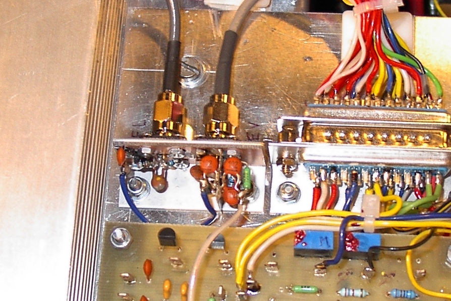
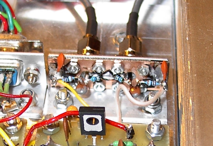
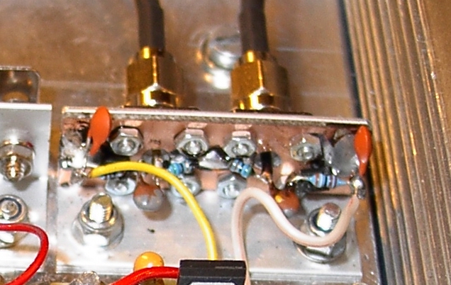
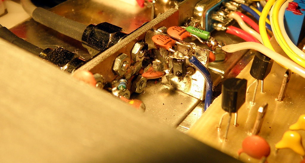
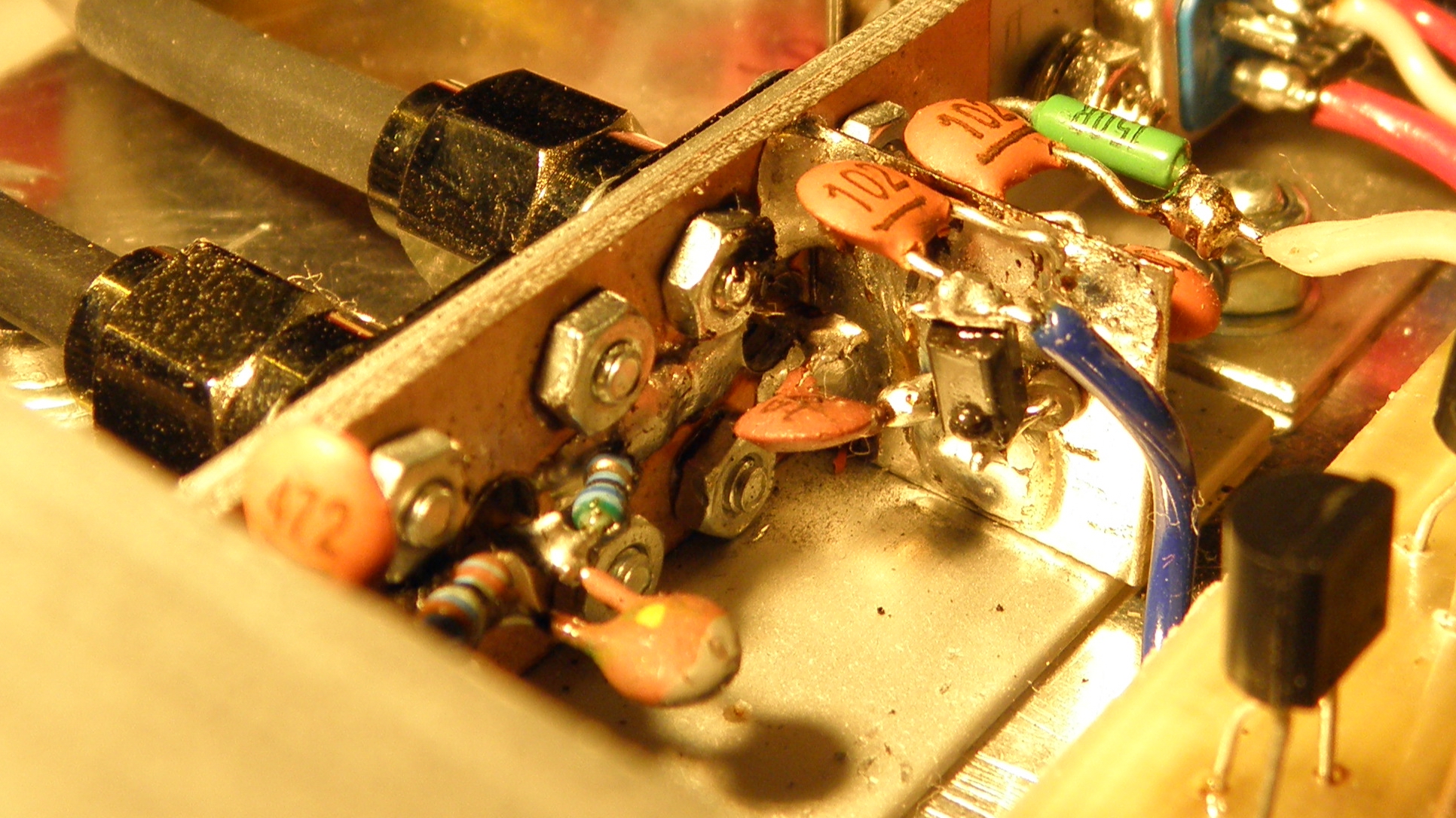
In the article focused to the mechanic construction of our new SSPA has mentioned protection circuit focused to the RF limit and SWR protection as well as monitoring of balance of both parts of PA. For such RF level monitoring are needed detectors of small RF power. Maybe the below notes would be helpful for your own construction of similar SSPA: First of all I should emphasize, that this article is not focused to the sophisticated commercial RF detectors, for example ADL5504, of course not because it would be not perfect solution for some specific demands, but because I did not need such detector in our PA. My solution is wholly primitive and thousands time used. The reason, why this article has written is prozaic. Within measurment of PA I made some notes of used detectors and when it was already saved in PC, I thought it may help to someone sometimes if it will be on the web. Detectors in my PA were realized as twin detectors on AL "L" form profile 15x15x1mm and with lenght cca 5cm. Each of detectors begin with SMA connector and a strip of double sided PCB 1mm thick and cca 14mm wide, fixed to profile by 4 srews M2 of SMA connector flange. To prevent problems with length of coaxial interconnection to detector (for example from directional tap), it should have an impedance as close as possible to 50Ohms. This is realized by miniature metalized 56Ohms resistor with 400mW pwr limit and lenght of body cca 4mm. Local electronic devices shop has them below name MRR56R. From the centre of SMA the RF sample is connected via coupling capacitor to Schottky diode rectifier and from the cathode of diode the DC voltage is connected by 2k7 isolating resistor into operational amplifier input shunted by RF blocking capacitor 1nF (part of comparator) with very high input impedance. The open detector construction of course need to keep UHF construction principle - consider each milimeter of any wire lenght. Schematic is here: Detection
Schottky diode in the sample was old Slovak KAS31, but it's fully
repleceable by ordinary BAT15,
Within measurment I have changed value of C1. Results are in the table:
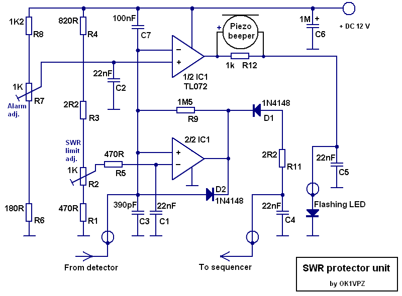
Rectified DC voltage may of course be different in the accordance of detection diode capacity, but is clear, that for such simple sensor on 70cm is not needed more sophisticated detector (for example this one). This detector even can be used up to 23cm, if the C1 will be 1pF - and it was not anticipated indeed... If you need to detect higher pwr level, of course the load resistor must be able to absorb it and have an appropriate cooling - but you need as well as to decrease capacity of C1. Because such capacitors with 0,2pF and less are not available, use on this place small metalized rezistor abt. 1MOhm, which will have such small capacity. In any case the maximum detected DC voltage should not exceed cca 8V DC, because Schotky diode have max. reverse voltage usually abt. 20V max. For SWR protection such detector is not usable of course, because reflected power has normally much lower power compare FWD PWR (both RF samples of RF are of course divided by directional coupler), because RF signal will be below detection ability of Schottky diode. Thus is needed the RF signal reflected from antenna to amplify. This solution has been desribed already here, and in this PA has used schematic shown below. Mechanic design of detector uses the same devices as above, only piece of tinned plate in the size cca 14x20mm with few small holes for amplifier:
And there are measurment results of such detector:
Measurment results shows, that active detector is usable well for SWR protection, albeit the input reflection attenuation on 23cm is already not good enough. But it could be fixed by use of different MMIC amplifier or by some compensation. However - if the detector will be installed in the PA with fixed length of coax cable between directional coupler and detector, mistake of measurment could be compensated by adjustment of protection unit and thus will be not harmful in practice. The last issue is suitable directional coupler. For our 70cm SSPA with 800W RF has been used directional tap from GSM surplus by Kathrein and which still time to time are for sale on flea market. Here is the measurment result (avg from 3 pcs):
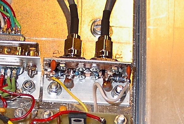
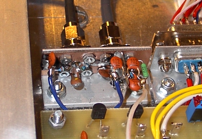
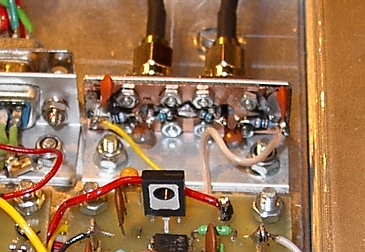
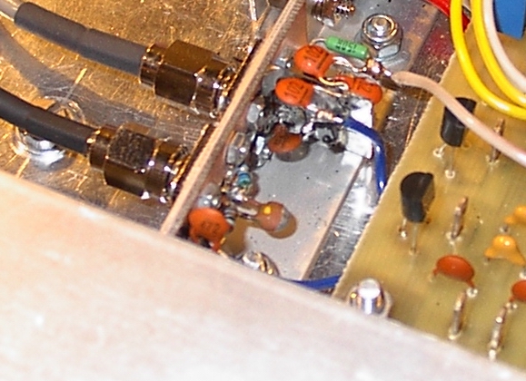
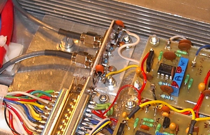
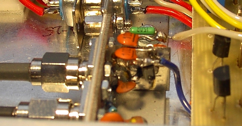
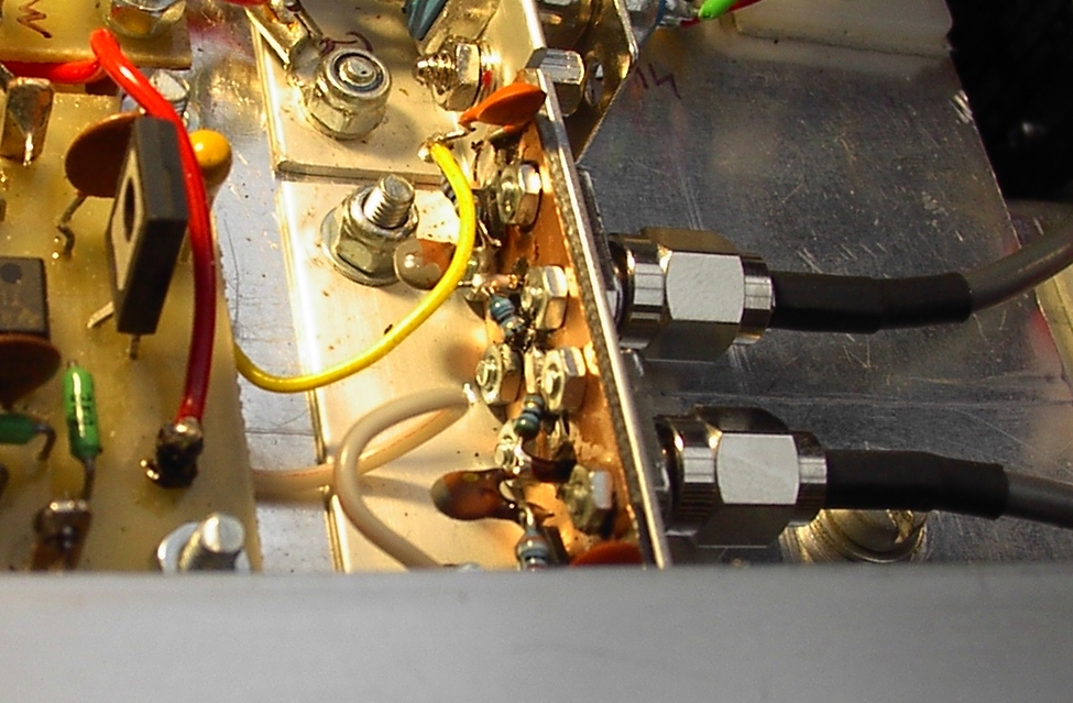
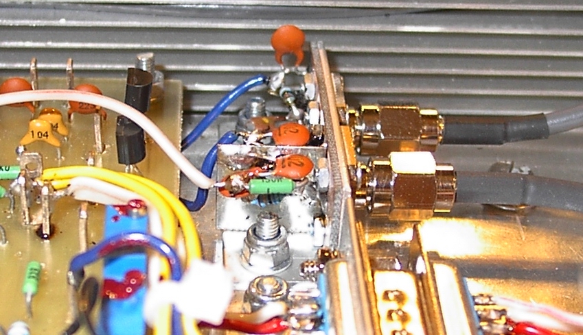
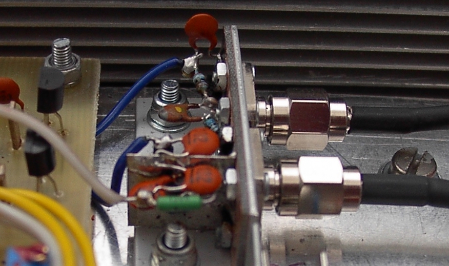
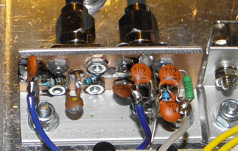
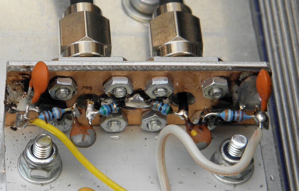
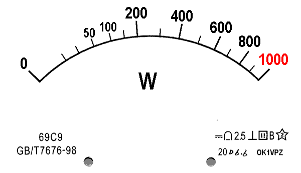
And now few comments to the directional tap measurment results: With forward PWR 800W (+59dBm) will be on 70cm level on the (FWD) tap of coupler abt. +22dBm (160mW), thin cable interconnection to the detector add some 1dB and on the output of simple detector we can await cca 1,8V DC. It is not a much, but in case of use of wattmeter with operational amplifier (consisting of PEP detector) the measurment will be good enough. If you want, the scale for cheap chinese measure you can download here, print out on self adhesive label and stick on. If the reflected power will be 50W (+47dBm) we can await on the tap cca +10dBm (10mW) signal, what in case of use of active detector create decrease of output voltage from 5 to cca 2V, what is substantial change, which we can evaluate by some simple comparator and make an alarm or stop the TXing to prevent PA from damage. I hope you may consider this large description of the very ordinary matter as useful. For final few pics of detectors: 73 de OK1VPZ
| ||||||||||||||||||||||||||||||||||||||||||||||||||||||||||||||||||||||||||||||||||||||||||||||||||||||||||||||||||||||||||||||||||||||||||||||||||||||||||||||||||||||||
_small.jpg)