|
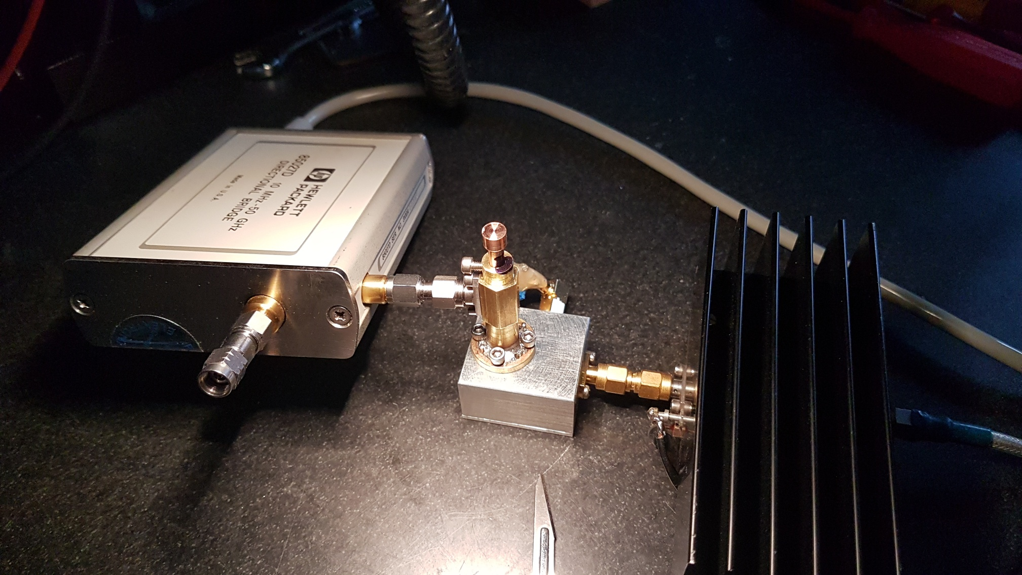
47 GHz EME – „facts and findings“ [2020] Progress with 47 GHz EME in 2019 DL7YC & DC7KY (translated into English by Matej, OK1TEH) In February 2020, the 42nd Microwave Conference, held in Dorsten where Klaus, DC7KY and Manfred, DL7YC gave a lecture on the history and current capabilities of 47 GHz EME. The lecture has based on experience and large knowledge (as of January 2020) from more leading stations focused to this band such as Mitsuo JA1WQF, Jose EA3HMJ and Iban EB3FRN, Hans PA0EHG, W5LUA, VE4MA, K6MG (ex. AD6FP), DC7KY, DL7YC and Sergei RW3BP as a background consultant (although he currently experimenting rather with 76 GHz EME hi). DL7YC continue: together with Klaus DC7KY, we have been intensively working on this topic during 2019 and the result is this article where, although the EME contact with W5LUA has not yet taken place, we can already announce some partial successes. Measuring technology Proper measuring technology is always a key element of any serious work on microwave bands. In the 47 GHz band, the measurement of parameters is a bit more complicated, because the usual 50 GHz VNAs with accessories are very expensive and only a small number of amateurs own them.
During 2019, I was
pleased to expand my measuring components by a few new
parts.
Interestingly, I found that K-type connectors aren't so good for measuring
on 47 GHz. The K-type connectors are usable, however, just like SMA
connectors on 24 GHz, you can't make any accurate measurements with them!! Thus, it is clear that the utmost attention must be paid to both parameters, the precision of the dish surface AND its shape. It is no coincidence that “professionals” use rotary solid parabolic reflectors up to 122 GHz! Based on this knowledge, we asked the dish manufacturer to check whether the accuracy of the production mold would fit the 47 GHz band. We took advantage of the fact that in 2018 the manufacturer intended to check the surface accuracy of the 2.4 m dish with a specially designed optical measuring device. The mirror that was measured by the manufacturer had a diameter of 2400 mm and a focal length of 910 mm (f/D = 0.385) and the method for measuring these reflectors is the so-called Photogrammetry. Unfortunately, after completing the measurement, the manufacturer could not improve the accuracy below 0.5 mm. But sometimes you're lucky!! In the end, the actual value seems to be much better, as shown in Figure 2 below. In the picture you can see the reflection of the Sun reflected by two narrow reflective strips perpendicularly glued to the dish surface.
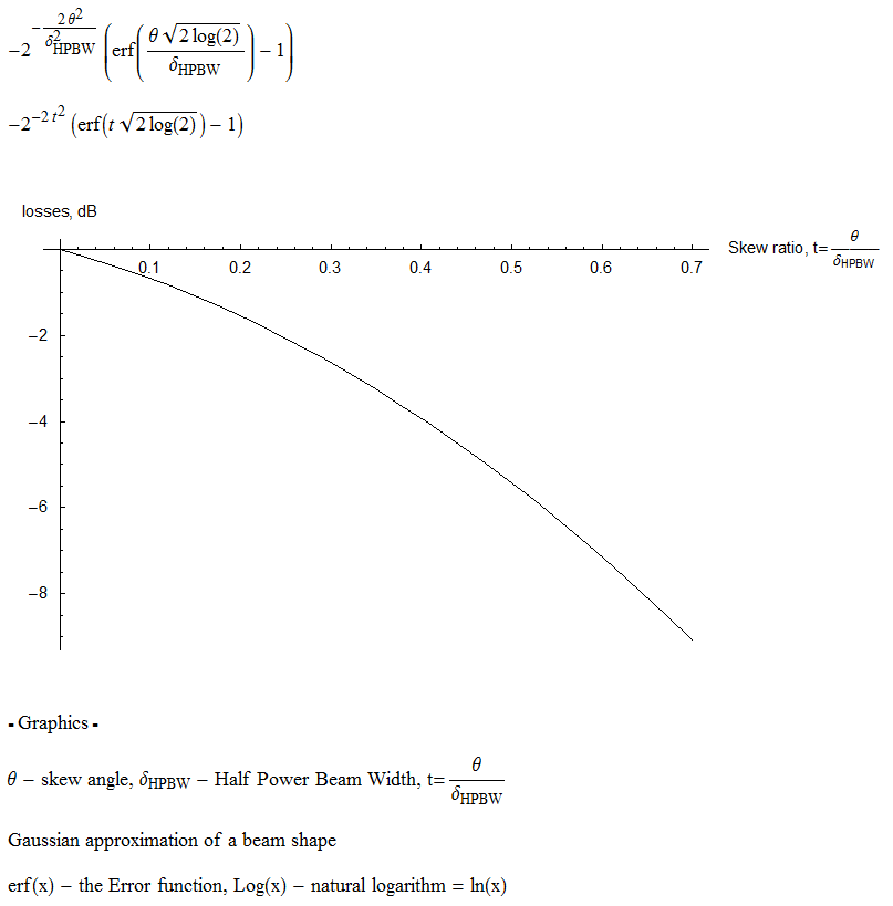
Amazingly, it turned out that tracking the Sun with the dish was EASIER than at 24 GHz. What caused it? The -3dB opening angle of the antenna is only 0.19 degrees at 47 GHz - but the Moon is about 0.5 degrees wide when it's viewed from Earth. Since the electromagnetic radiation from the Sun "apparently" goes from a disk (the edges are further away, but it is not coherent radiation, the phase position is irrelevant), you can move 2.5 times over the Sun with the antenna lobe, before the level changes !! A completely unexpected phenomenon... In the case of echo tests,
however, the situation is exactly the opposite. As Dimitry, UA3AVR has
impressively calculated, if the center point of the "spot" generated on
the Moon is 0.026 degrees wide for -1dB, signal is lost and if the
inaccuracy from the center of the moon is 0.015 degrees, it results in
-0.5dB loss.
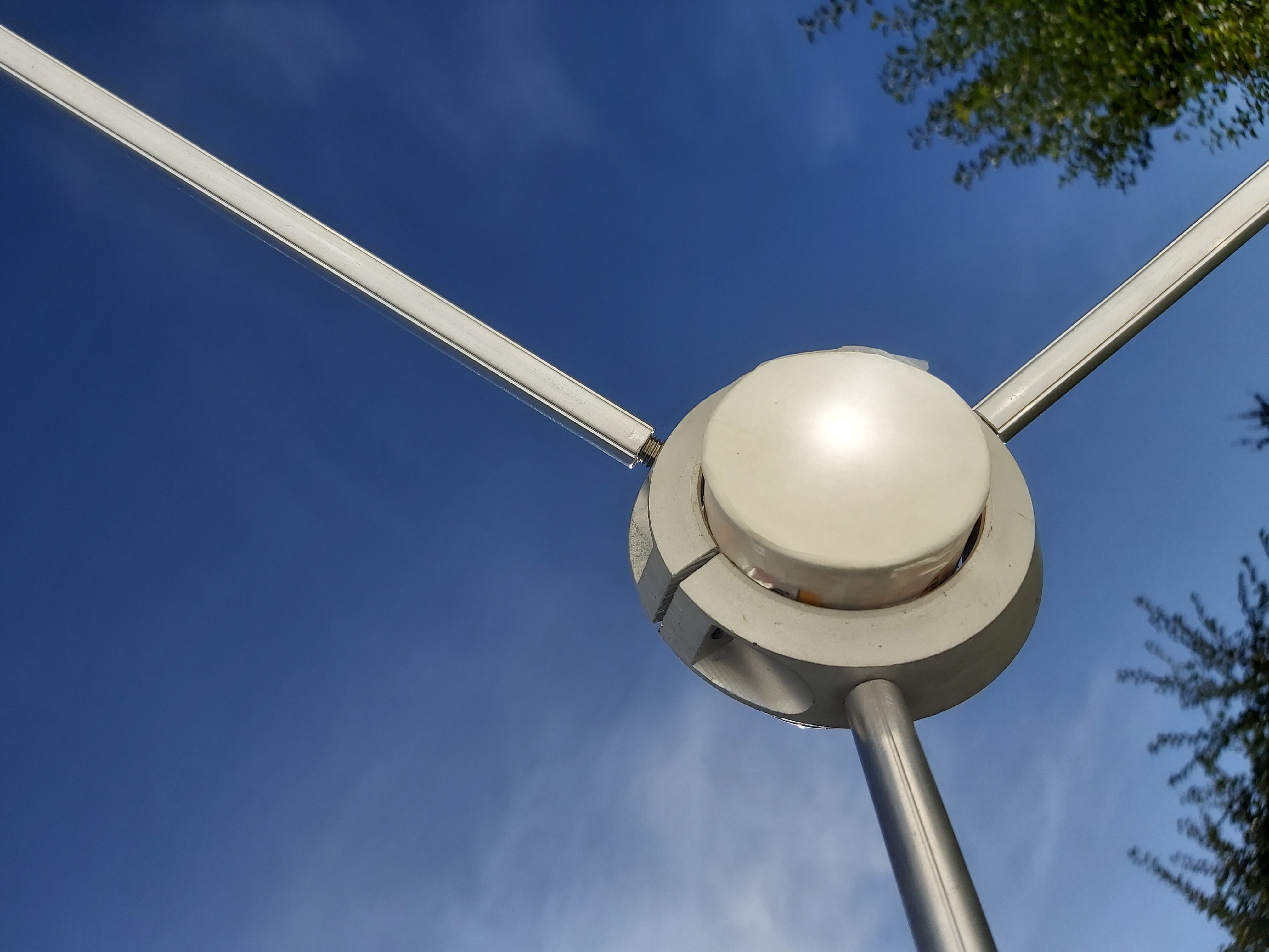
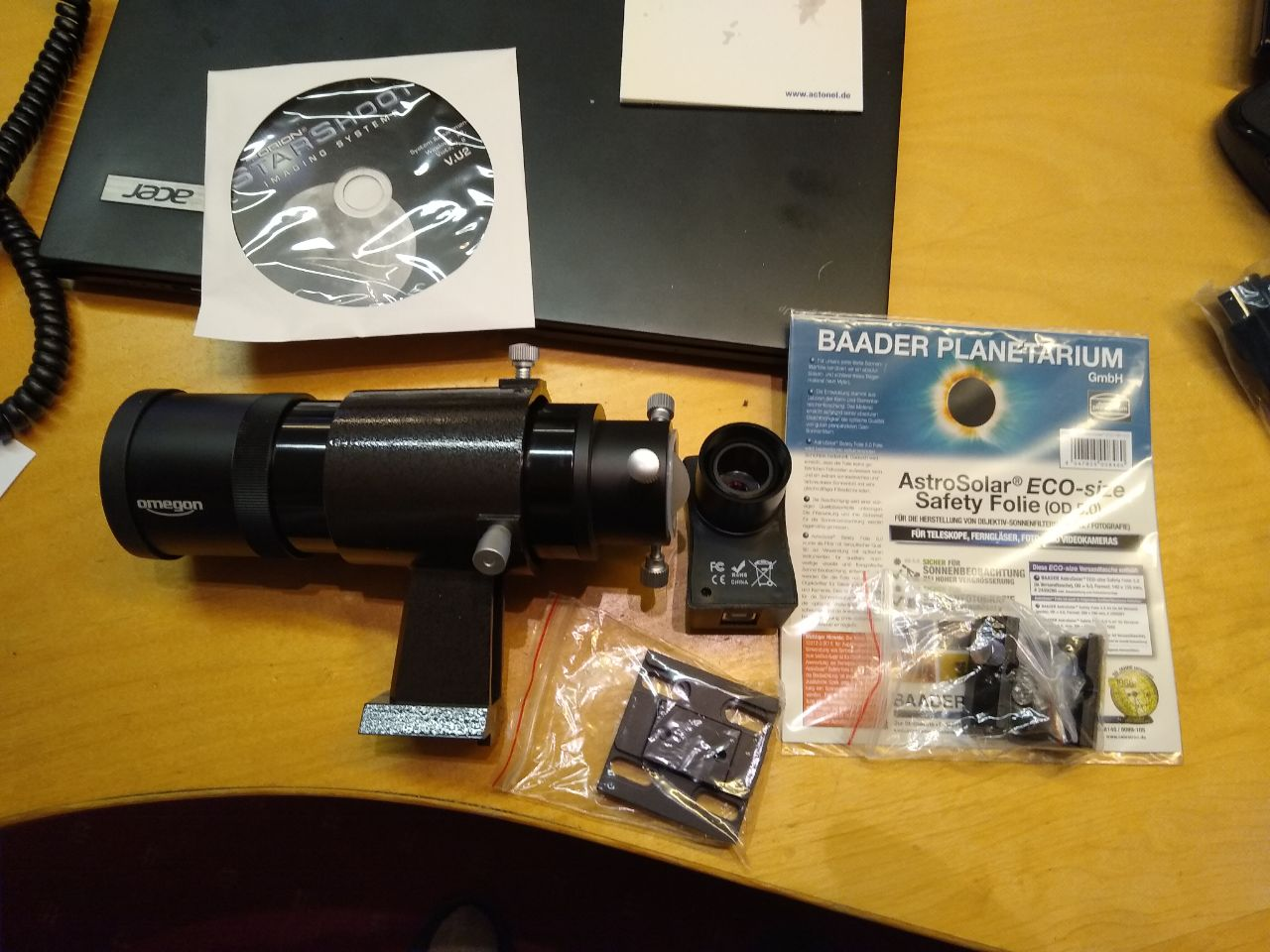
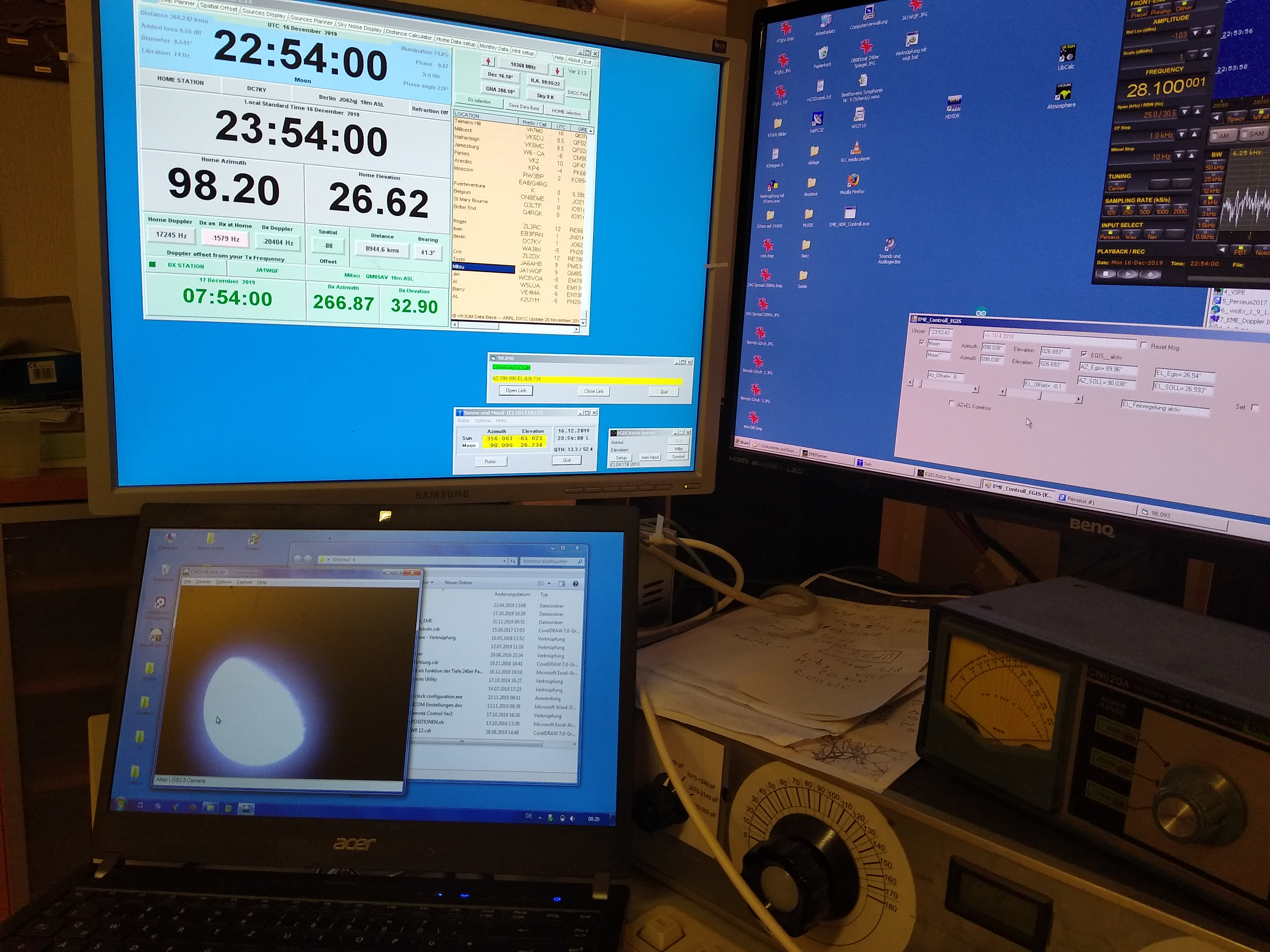
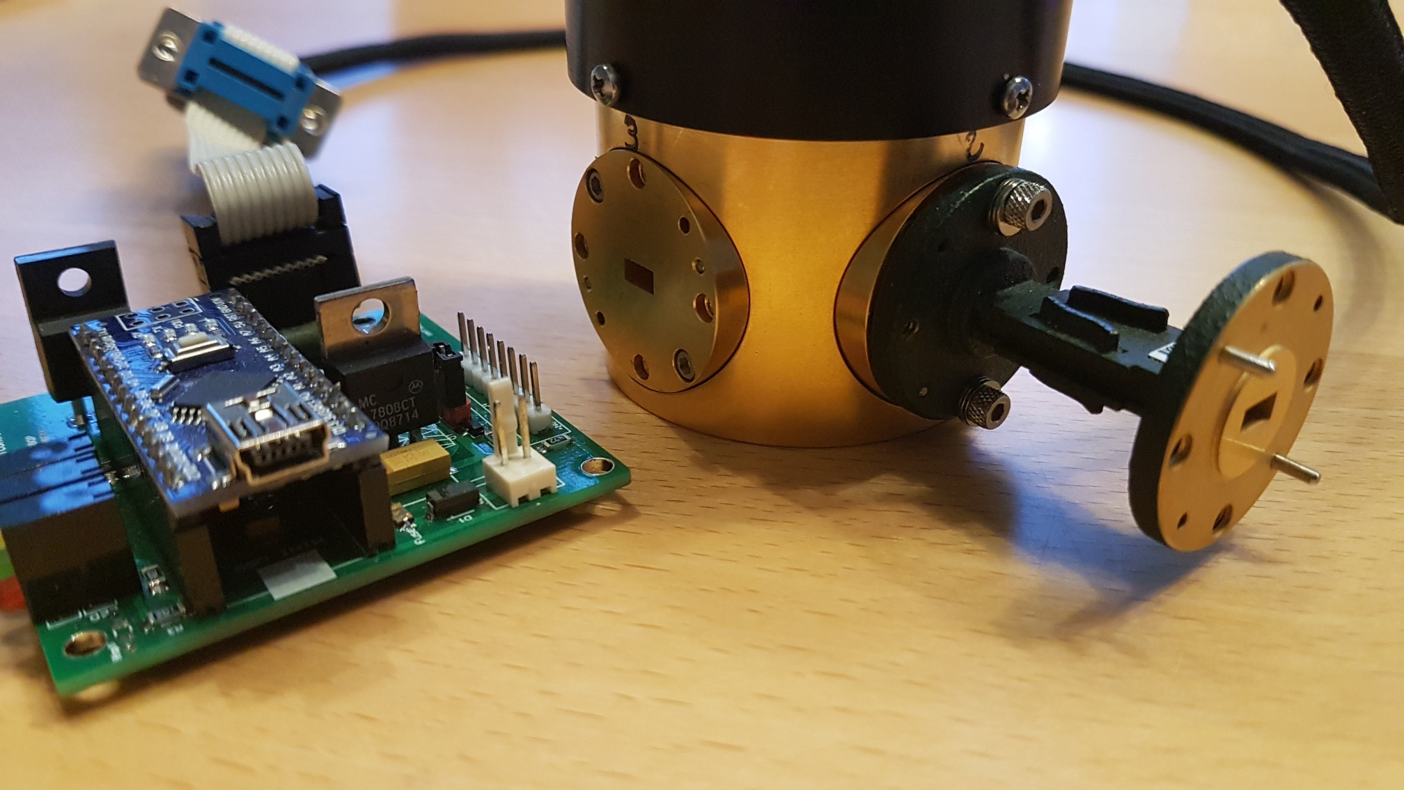
The required viewing and tracking accuracy is hardly achievable under amateur conditions. However, the optical sighting method known from the beginnings of EME operation, as DC7KY did in this case (but only works with cloudless sky), can be used: Moon tracking using a high-resolution astro lens and web camera. You will quickly realize that only well arranged Moon tracking is really effective because it keeps the antenna's weight in motion without shaking.. Another ongoing project is the modernization of EGIS rotors using stepper motors. (Source for camera, lens and sun and moon filters for € 285, - available here: www.astroshop.de / Omegon Module Finder, Orion StartShoot US, Omegon Advanved Finder Base, Omegon Finder Shoe Vixen, Bader sun filter film) Note
OK1TEH: Another option is to use the F1EHN tracking system for automatic
tracking, which allows you to rotate the antenna when using a multi-bit
encoder with an accuracy of up to 0.01 degree. Such a system is used for
example by OK1KIR, where they rotates with 4m dish with accuracy 0,02deg
using IRC sensors produced by Czech company ZPA Netolice.
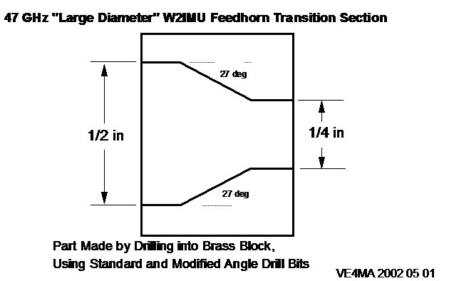
Feed-Horn As you can read in the W1GHZ's Antenna Handbook, a specially dimensioned feed horn is required for a certain F/D. For a cylinder dish (mostly F/D from 0.32 to 0.45) is suitable VE4MA super-feed-horn with a narrow rim. For an offset dish you need a primary feed with much more gain, ie with a smaller opening angle and thus a larger aperture area. The feed horn usable for 47 GHz EME must have a waveguide output (WR-19 or WR-22) which allow connecting it directly onto the RX/TX WG switch. Now the network analyzer with reflection bridge mentioned above is used again. In both of the primary emitters mentioned above, "beam forming" attempts to achieve a somewhat more rectangular assignment of the main reflector. 1) With the Kumar horn, VE4MA has reached a middle indentation of the lobe by choosing the outer ring trap, thus producing a higher energy density on both edges; the so-called VE4MA Superfeed .... 2) In the multi-mode emitters, a higher energy density is generated on the secondary emitter by superimposing the TE10 wave with a TE20 wave (transitional widening of the emitter). Such a solution is suitable just with a larger F/D ratio. The transition section that creates the second mode is shown separately at next picture. The accuracy of compliance with the feed dimensions should be better than 0.1mm - at 47 GHz the accuracy should be around 0,02 - 0,03 mm.
Initial "blind attempts" to optimize feed without using a network analyzer were not very successful. The feedhorn should have at least a Return loss (SWR <1.2) of 20dB, so that a) The LNA will not oscillate and b) The measured NF values can be transferred into practical operation. To measure the Return Loss values (RL) of the various feeds we used the coaxial 50GHz measuring bridge, five WR19 waveguides/coax adapters with precise K-connectors (made during Spring 2019). By comparing the length of the center conductors and the spacing of the back shorts, excellent transfer values could be achieved (> 25 dB RL). The measured transmission loss was too high at approx. 1 dB. However, further measurements with these transitions repeatedly (if you changed the measurement configuration) led to strongly fluctuating results. Even the smallest changes in the length of the waveguide changed the measurement results on the feeds significantly. It must have been due to the K-connector, which is no longer suitable for 47 GHz, and in fact, waveguide/coax adapters with 2.4 mm connectors immediately made stable results! WR22 / WR19 waveguide switch As is well known, mechanical rotary waveguide switches for 47 GHz are very complex if a very low attenuation and good port isolation (> 60dB) between TX and RX is required. Home-made constructions of such a switch isn't a good idea! Thomas, DC7YS took on the task and built such a small WG switches for 47 GHz and 76 GHz. Even after gilding, they do not achieve the precision and low loss like the: Professional versions of FLANN Microwaves or Millimeterwave Products
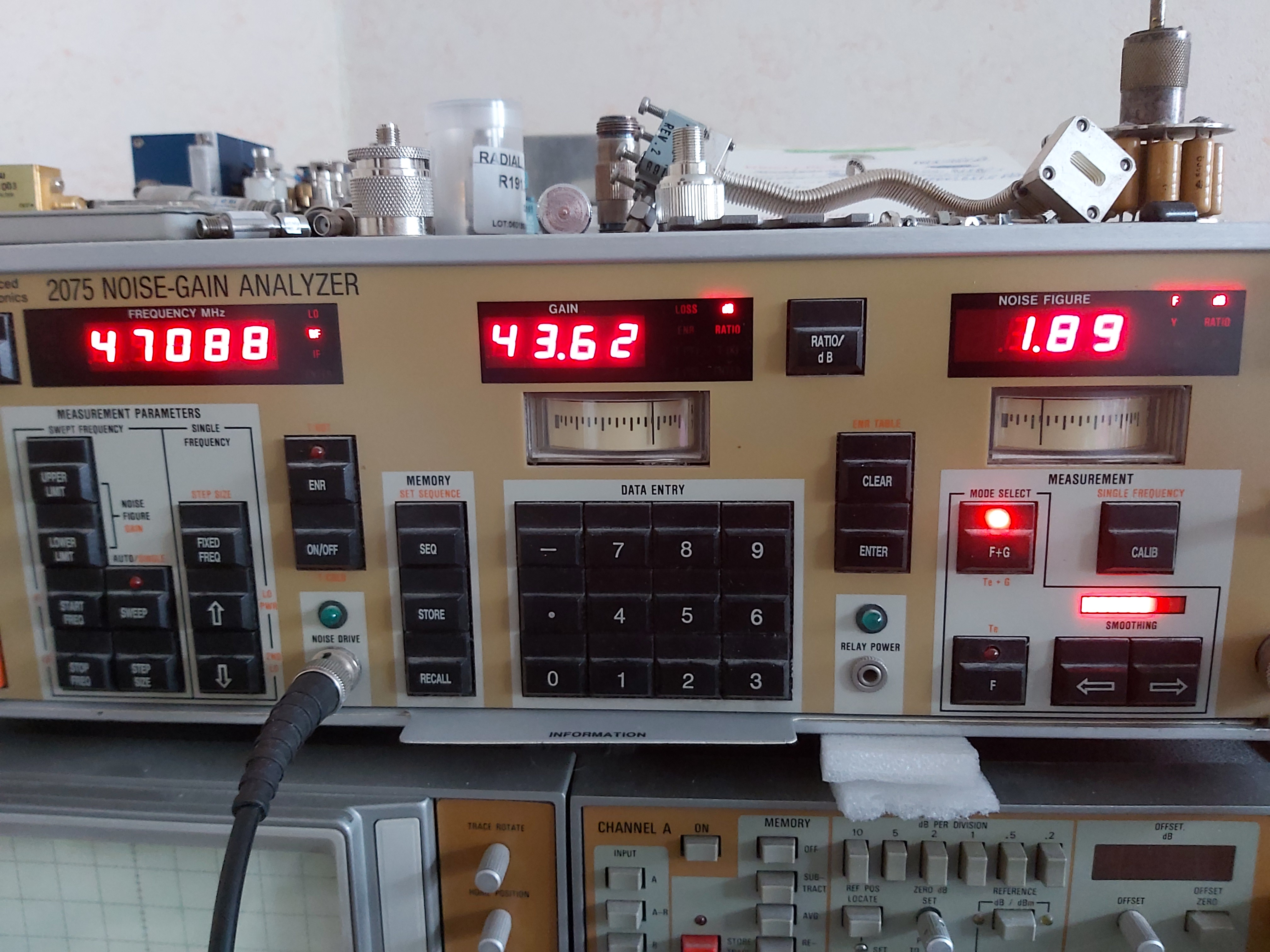
As already explained above, the (expensive) measurement technology helps us to find out such a differences. After changing the coaxial part of the network analyser to 2.4mm, we were able to determined that the loss of the whole chain (measuring bridge/coax transition/WR22 switch/ WR 22 detector) was about 0.1dB. 47 GHz low-noise preamplifier In the meantime, we have also continued to develop a suitable LNA. We bought 10 pieces of CGY2260UH/C1 MMIC transistors and produced several home-made waveguide preamplifiers. The achieved results are amazing!! In the first batch of 5 pieces of WR22 or WR19 preamplifiers, we measured gain over 20dB and noise figures about 2.3 - 2.0 dB @ 17 °C. Two chips became "victims" of LNA development and thus unusable. The second batch of 5 pieces is currently in production.
An attempt to cool the
amplifiers to 0 °C with cold spray improved the result of the noise figure
by 0.2 - 0.3 dB!! Note of OK1TEH: The problem where to get a suitable low-noise LNA is currently being solved by many stations that want to start EME experiments at the 47 GHz band. Production of such an LNA in domestic conditions is extremely difficult due to the unavailability of a high-quality noise number meter (or better said noise head) and another problem is the knowledge of bonding technology. If you don't have a quality laboratory, you can buy Kuhne 6mm LNA, which reaches about 5.0dB NF. Almost 0.5dB better LNAs were manufactured earlier by Ales, OK1FPC. If you are rich, you can get inspired by LX1DB, who ordered from SPACEK LABS (W6) fully customized LNA Model SL 472-18-3m which achieves 18dB gain and noise figure at room temperatures between 2.4 to 2.8dB.
47 GHz „Power-Amplifier“ The biggest problem of 47 GHz EME is to generate at least 10 watts of RF needed for EME contact. If you want to get more power output than the transverter does itself (50-100mW), you can use the TGA4046 chip from Qorvo (transistor is used at MKU PA 6MM PA). With this widely used chip it is possible to safely generate > 1.2 watts of power. EA3HMJ managed to get more power by combining these amplifiers. He combined two pieces of MKU 6mm PA and used the third as a driver. The results are shown below:
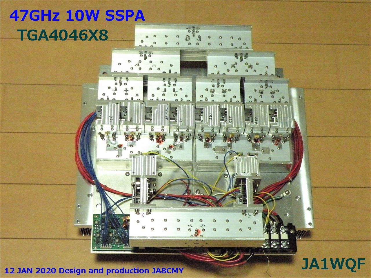
4 x TGA4046 (7-9 watts possible ??) The following picture shows an admirable attempt by Mitsu, JA1WQF and Yuki, JA8CMY for a 10W PA with TGA4046. Unfortunately, this amplifier is not yet fully functional, although half of the modules provide 5W of output power. The main problem is to combine the two halves using the correct phase alignment.
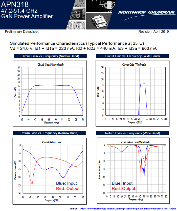
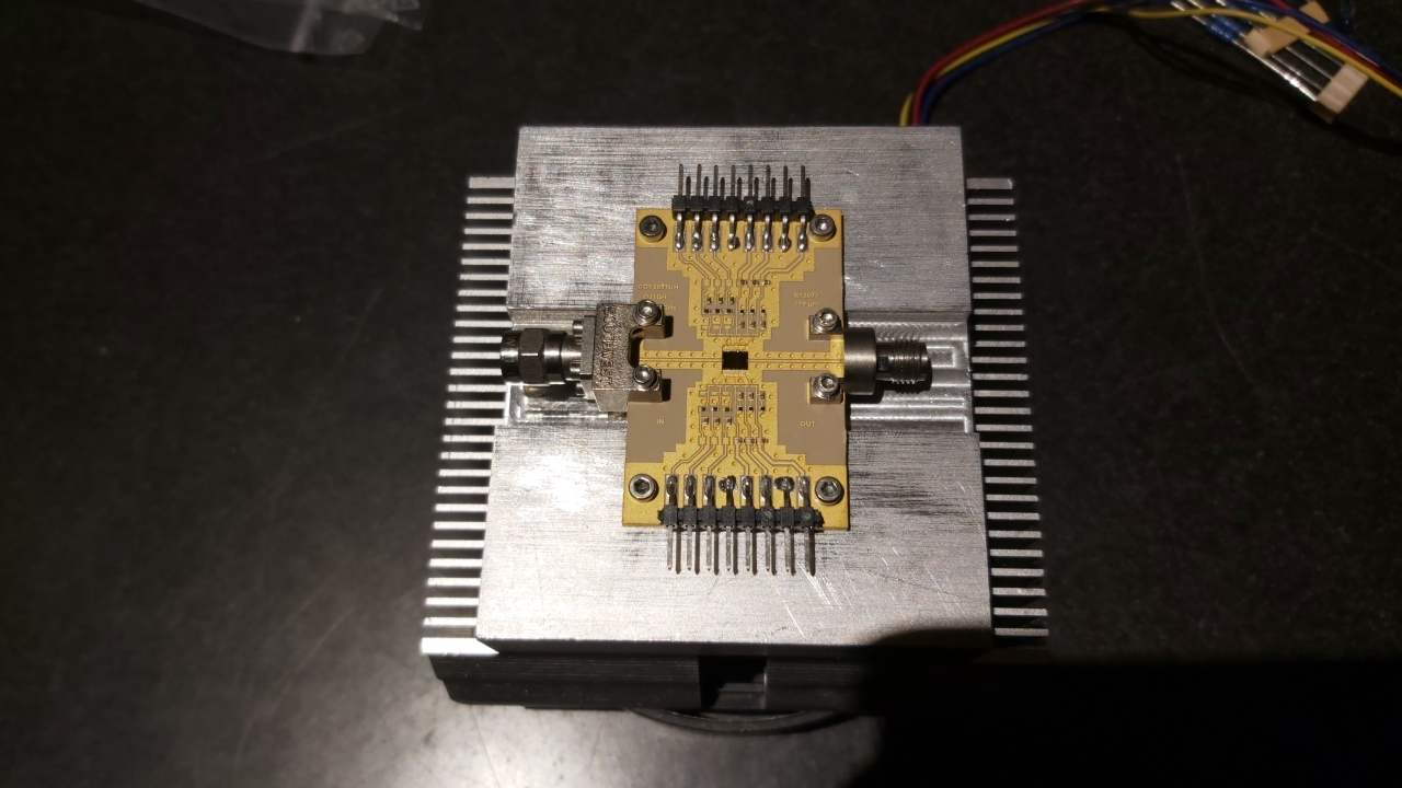
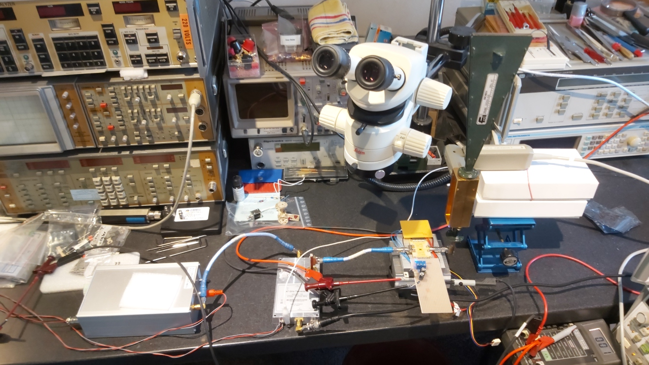
In any case, the driving power for such a 9-10 watt SSPA is 2x +30 dBm (> 2 W). APN167 (43-46GHz / 9 watts of saturated power output) As already reported in 2019, in addition to the well known TGA4046 from Qorvo, there also exist the APN 167 MMIC from the American company Northrop Grumman. Unfortunately, this technology is subject to the expanded American export regulations and it has so far not been possible to import this MMIC to Germany. (GaN Power Amplifier Web: http://www.as.northropgrumman.com/mps ) Thank goodness - you almost have to say, because for a short time 5G applications will become possible with new MMIC: APN318 (47 - 51GHz / 12 Watt of saturated power output) It is likely that as the 5G technology becomes more widespread, this MMIC chip will be much more available even in Europe. In the meanwhile, DL7YC is trying to make 10W PA with French OMMIC chip: CGY2651UH/C1 This OMMIC transistor is designed to deliver 10W output at the range of 37 - 43 GHz !! The published "On-Wafer" measurement data ends at 44 GHz, but still with the full saturation power of + 40dBm (10Watt). At the following pictures you can see DL7YC's tests with his laboratory setup:
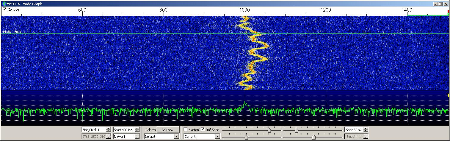
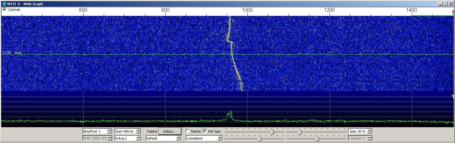
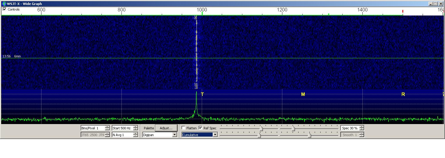
So far, it doesn't look very promising that I could achieve the expected performance with this chip, and by the time this article comes out it is uncertain whether this chip can be used. According to Sergei, RW3BP, it seems much more difficult to use the chip at the higher frequencies for which it was designed than vice versa. The power dividers / couplers at the chip can be influenced in a certain range by adding external transformation elements, but unfortunately not the elements around the middle stages. However, we haven't given up yet, and in case of success we will inform you. Oscillator stability Up until a few months ago, we all, including the author, believed in the frequency stability and accuracy of GPS-disciplined LOCAL oscillators. For the first time I became changing my opinion in early 2019 during the occasion of a 47/76/122 GHz session with the participation of many portable stations. Why does the CW signal sometimes sound so “rough” - and at SSB is signal sometimes unreadable? And I forgot it again - until Klaus, DC7KY was obsessed with the idea of using WSJT, especially JT4G or JT4H at 47 GHz EME. As is known, the such a mode is based on the transmission and reception of 4 different frequencies with 3 equal intervals. Due to the Libration on the EME path, reception of EVERY of these 4 tones will result in more or less large frequency distortions. The "art" of the decoder is to create a unique QRG assignment of the transmitted frequency, even if there is a significant deviation from the center frequency. This works quite well until the tones are lost in the noise (even if the decoder knows when AND where noise increases SHOULD occur). Now it quickly becomes clear that any additional contribution of a statistical deviation from the (transmitted AND received) frequency can make decoding difficult or impossible !! This prompted Klaus to conduct a comprehensive, week-long investigation of all available GPS-controlled OCXO's and Rubidium standards. As a result, except one, they were all unusable for the 47 GHz band !!!!! Below are a few pictures from the test series. You can clearly see what is useful - and what isn't. The control loops of the 10MHz oscillators are usually not designed for "end use" in the mm-wave range. The actual 10 MHz frequency is always reached - but with often “moving” into the surroundings. A deviation of 0.1 Hz at 10 MHz leads to a deviation of 47 Hz @ 47GHz! The deviations are often much larger, which has catastrophic effects. There are also big differences in the accuracy of the actual GPS receivers. These additional fictitious 47 Hz, occurring at the wrong time, can “shift” the transmission signal in addition to the Libration, for example, and cause the WSJT decoder to record a tone higher (or lower). This makes error-free decoding impossible even with sufficient signal strength. The above explanations also make it completely clear why a Libration of 150-200 Hz obviously marks the absolute upper limit when transmitting digital signals. Then it is possible to use ONLY CW (with quality of signals similar to for Rain Scatter)! Back to the 122 GHz portable station: For reasons of simplification, I used a MORION 10 MHz oscillator without GPS. It may not always be on the right QRG, but it doesn't "wobble". So as you can see, thanks to EME experiments it is possible to gain knowledge useful in a completely different topic!!
All WSJTX pictures show transmissions directly on 47 GHz and separate reception again directly on 47 GHz !!! The spectral images are examples of a large number of GPS-disciplined oscillators that have been investigated and were selected randomly. (OK1TEH's note: When I asked Manfred about Leo's Bodnar GPSDO http://www.leobodnar.com/shop/index.php?main_page=product_info&cPath=107&products_id=301 , he answered me "As far as I know, the Bodnar GPSDO IS VERY bad and not usable for 47 GHz EME yet.") Sun / Moon tracking of the dish at 47
GHz
In order to automatic tracking - "keep the dish on the Moon" by means of a control by means of a Moon noise meter and control optics, as already stated, further efforts are required, such as replacing the DC motors with stepper motors and tensioning the internal gear ratios. Appropriate components are available and are in the test phase. It is known from the 24 GHz band that it's possible to tolerate inaccuracy of dish tracking, if it reduces the Moon noise from 1.7dB by 0.1 - 0.2dB! At 47 GHz, the requirements increase again because the full moon diameter is no longer illuminated. As already described above, even the smallest deviations from the center of the moon lead to a considerable loss of signal. The antenna had to be updated at least every 15 seconds at 24 GHz; at 47 GHz, this value then drops to 3-5 seconds tracking update - or better: continuous tracking using stepper motors solves the problem of the accuracy and the vibrating masses of the antenna with greater angular acceleration. This is also a finding resulted from the measurements of Moon and Sun noise !! Negative influence on the transmission
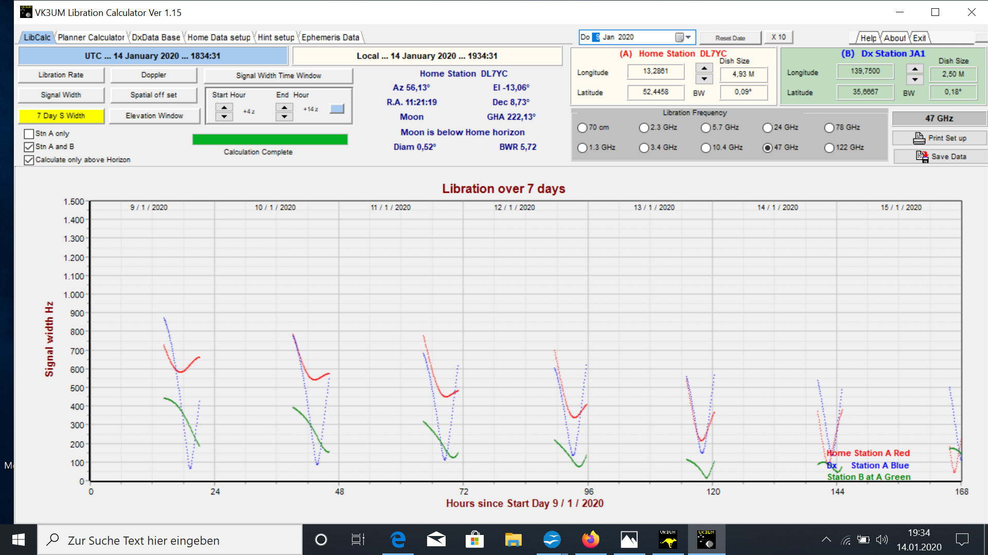
path through additional attenuation (EMEcalc, Atmosphere Absorption and LibCalc from VK3UM SK) Libration influences by spreading the
backscattered signal from the Moon.
With an elevation of 45 degrees and an
assumed atmospheric attenuation of 0.2 dB / km @ 47 GHz, the additional
signal loss in the atmosphere is approximately 2.0 dB / transmission
distance. Under an elevation of 20 degrees, the loss is already 3dB !!
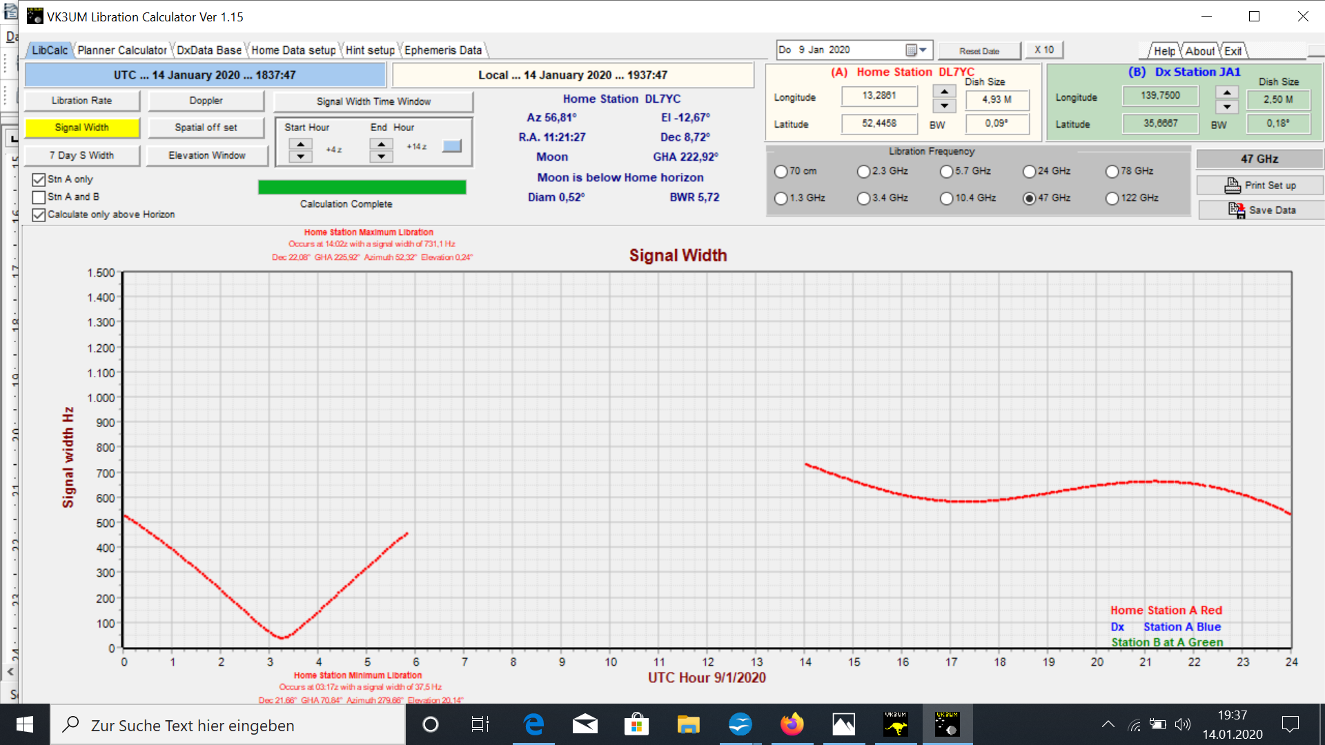
Fig.17– Graph of the spectral width of the echoes as a function of the elevation angle. Minimum at 03:15 UTC. Choosing the right time for a QSO or just for the echo test is extremely important, because when you distribute the backscattered energy over a large audio frequency range, you may not be able to hear anything or see it in the waterfall graph. However, there is a conflict between the smallest spectral width (spread) of the signal (during minimal Libration), which only occurs in the temporal proximity of the Moon rising / setting, and the associated longer path of the signals through the atmosphere, and the lowest atmospheric attenuation, that can only be achieved at high elevation angles. With high elevation, however, the Libration also reaches a maximum !! The best possible time for maximum echoes will have to be determined in more precise experiments; may be it's around 25 - 35 degrees of EL..
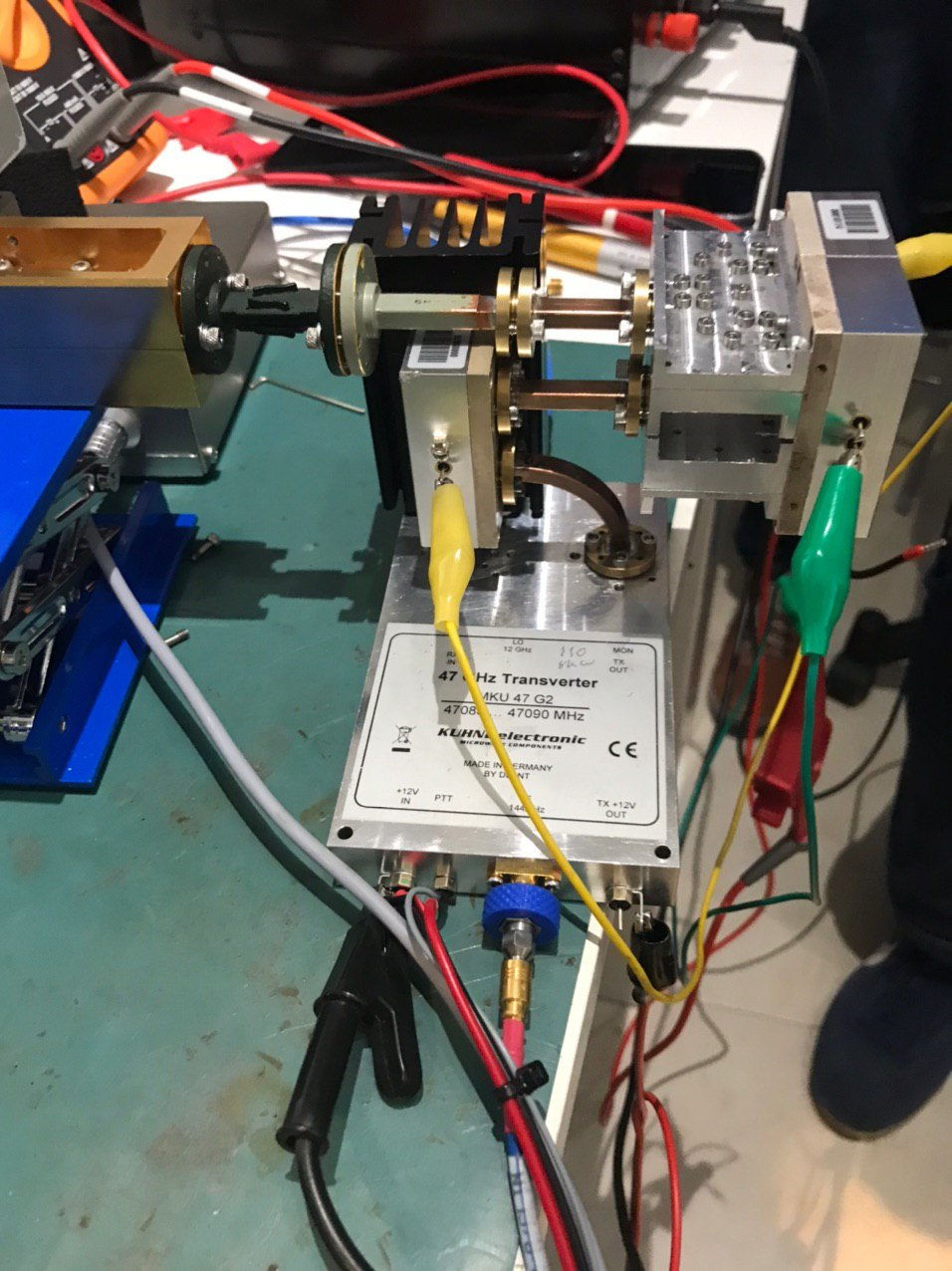
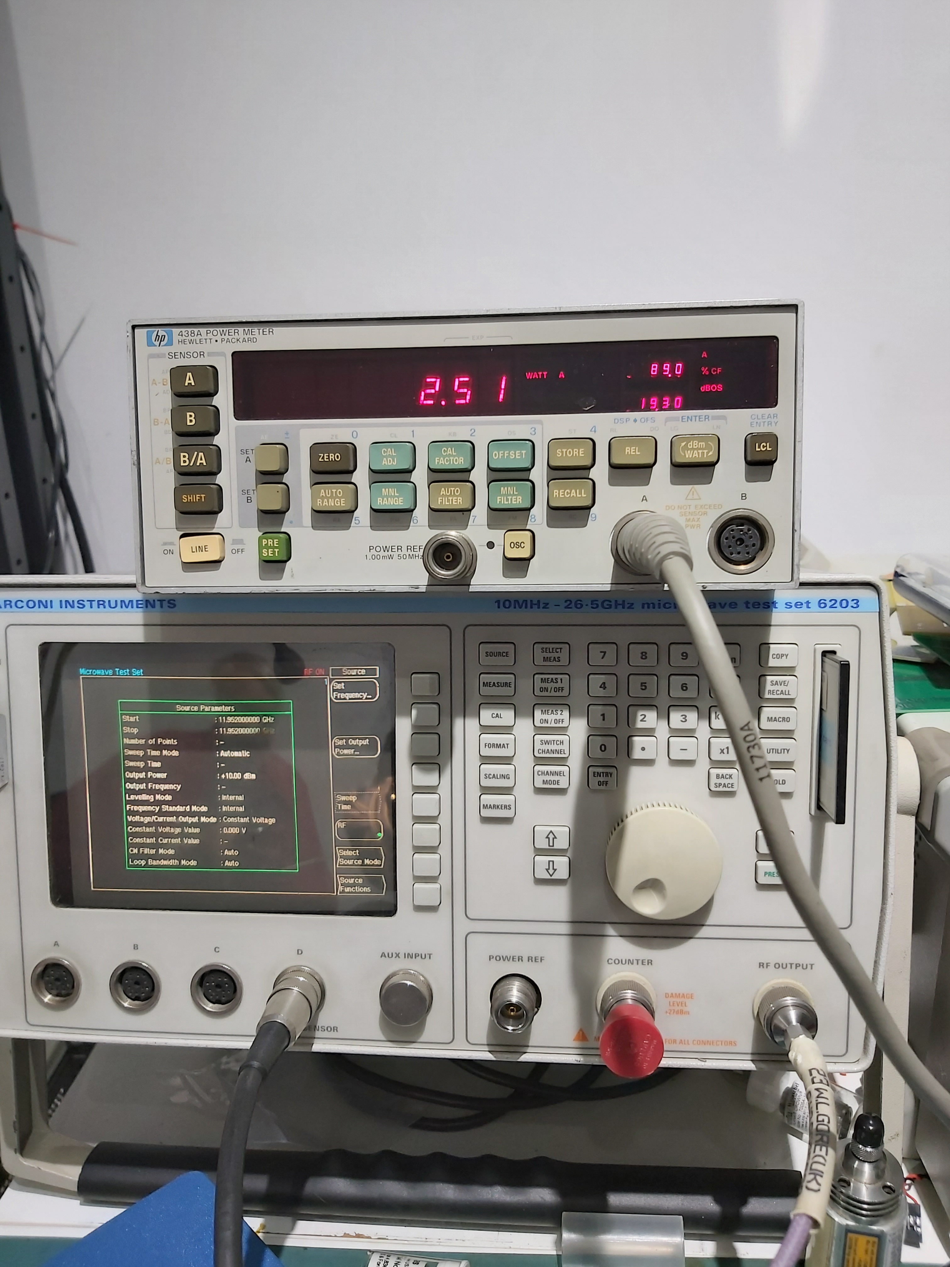
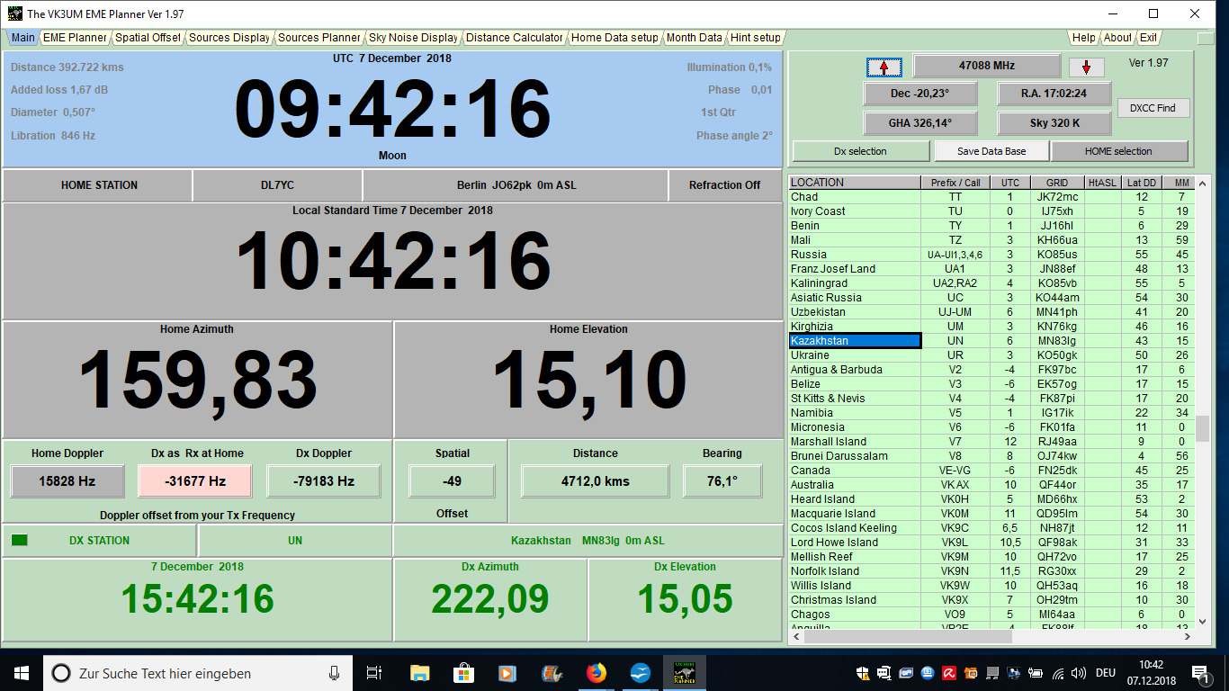
Fig.18 - Frequency-dependent “realtime” display of two EME stations. If you simulate a possible 47 GHz EME QSO between UN6PD in Kazakhstan and DL7YC in Berlin, you can see in the small field "SPATIAL OFFSET" in picture J, there is a polarization angle offset of - 49 degrees between these two stations - not ideal and an additional loss factor. The only way to deal with this is through technical measures, such as “twisting” the feed or twisting the waveguide. For example, JA1WQF installed such a 38-degree waveguide twist for attempts to receive the signal from W5LUA from Texas, according to its feed. Measurement of Sun noise @ 47 GHz Here are the current "State of the Art" values, measured by JA1WQF in January 2020 with his new 2.3dB preamplifier and 2.4m Cassegrain dish. > 8.9 dB, measurement of Moon noise> 0.9 dB The mentioned numbers fluctuate depend on the air temperature, the water vapor content of the air, the elevation of the both antennas and numerous other factors. DL7YC has just started a series of measurements, the results of which were not yet available in February 2020. The results will be reported on at the 2020 GHz conference as part of the presentation. Because the LNA sensitivity could be reduced from> 5.0 dB to below 2.0 dB NF thanks to the use of new MMICs, a 2 way QSO is get "much closer". An increase of the PA power up to 10 watts RF through the use of new GaN ICs is imminent, push the “dream of 47 GHz fully solid state EME” within the reach. As can be seen in the following picture, the probability of a 2-way contact increases sharply with a decreasing noise figure and increased transmission power:
...and finally, an important reminder: According to the RUZE`s equation: (Quote: Source WIKIPEDIAA https://en.wikipedia.org/wiki/Ruze%27s_equation ) Ruze's equation is an equation relating the gain of an antenna to the RMS of the random surface errors. The equation is applicable to parabolic reflector and antennas, and recently extended to phased arrays. The equation is named after John Ruze who introduced the equation in a paper written in 1952.[11] The equation states that the antenna's gain is inversely proportional to the exponential of the square of the RMS surface errors. Mathematically, the equation for parabolic reflector antennas can be expressed as: G ( ε ) = g 0 – 685.81 ( ε / λ )2 (dB) where ε is the surface RMS errors of the reflector, λ is the wavelength, and G 0 is the gain of the antenna (dBi) in the absence of surface errors. ...Which means nothing else than dividing the measured RMS “surface error” by the wavelength (in mm), squaring it and adding 685.81 multiply. With an RMS of <0.5 mm at EVERY point of the reflector surface, at 47.088 GHz this results in a loss of 4.22 dB compared to the IDEAL dish !!! The loss of -4dB @ 47 GHz decrease the theoretical value of the dish gain from 59 dBi to 55 dBi. Assuming 60% efficiency, this corresponds to a -3dB opening angle of 0.17 degrees. As a reference: on 24 GHz the same RMS surface error value of <0.5mm "only" leads to a loss of 1 dB compared to the theoretical value of the dish gain of 53 dBi. This corresponds to 52 dB / -3dB opening angle = 0.35 degrees. What are the results of different measurement methods?? It is a well-known fact that the received and transmitted power is directly proportional to the size of the dish surface. Thus, larger dishes are preferable in case that they have sufficient shape accuracy (see the Ruze equation).
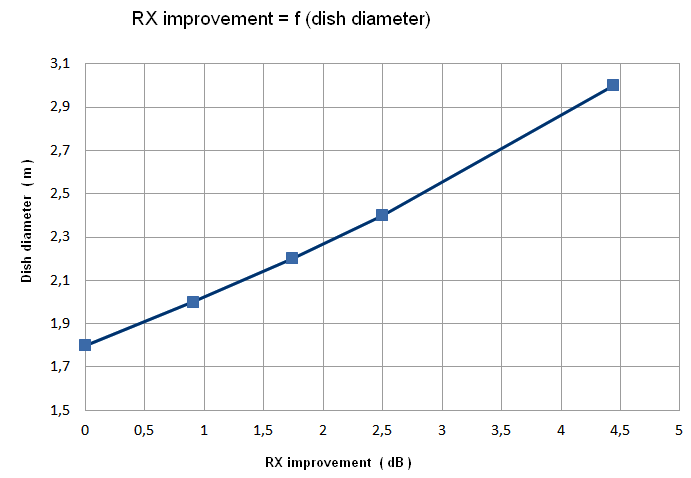
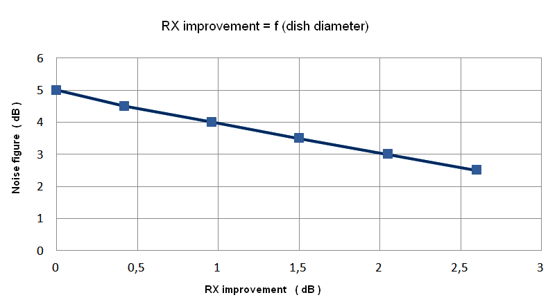
As can be seen from Fig.6, the choice of a
larger dish is responsible for a considerable improvement in reception.
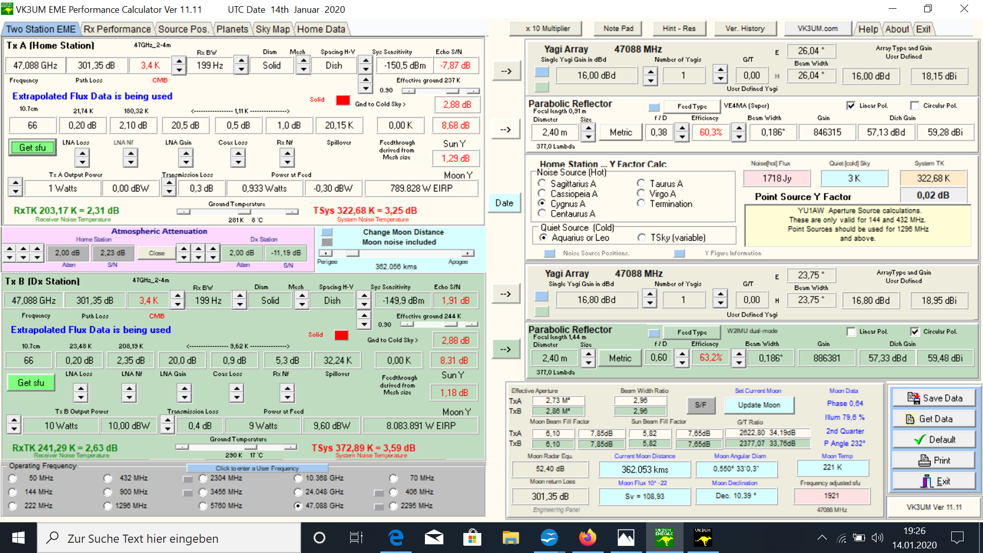
With this knowledge, the question of the available transmission power almost fades into the background. If a required power @ 47 GHz of> 30 watts was still assumed in 2005, today's calculations result are at much lower level. Based on the calculated values of the
VK3UM EME Performance Calculator, a transmission power on the feed of 2.5
- 5 watts on 47 GHz should be enough to be able to get Moon
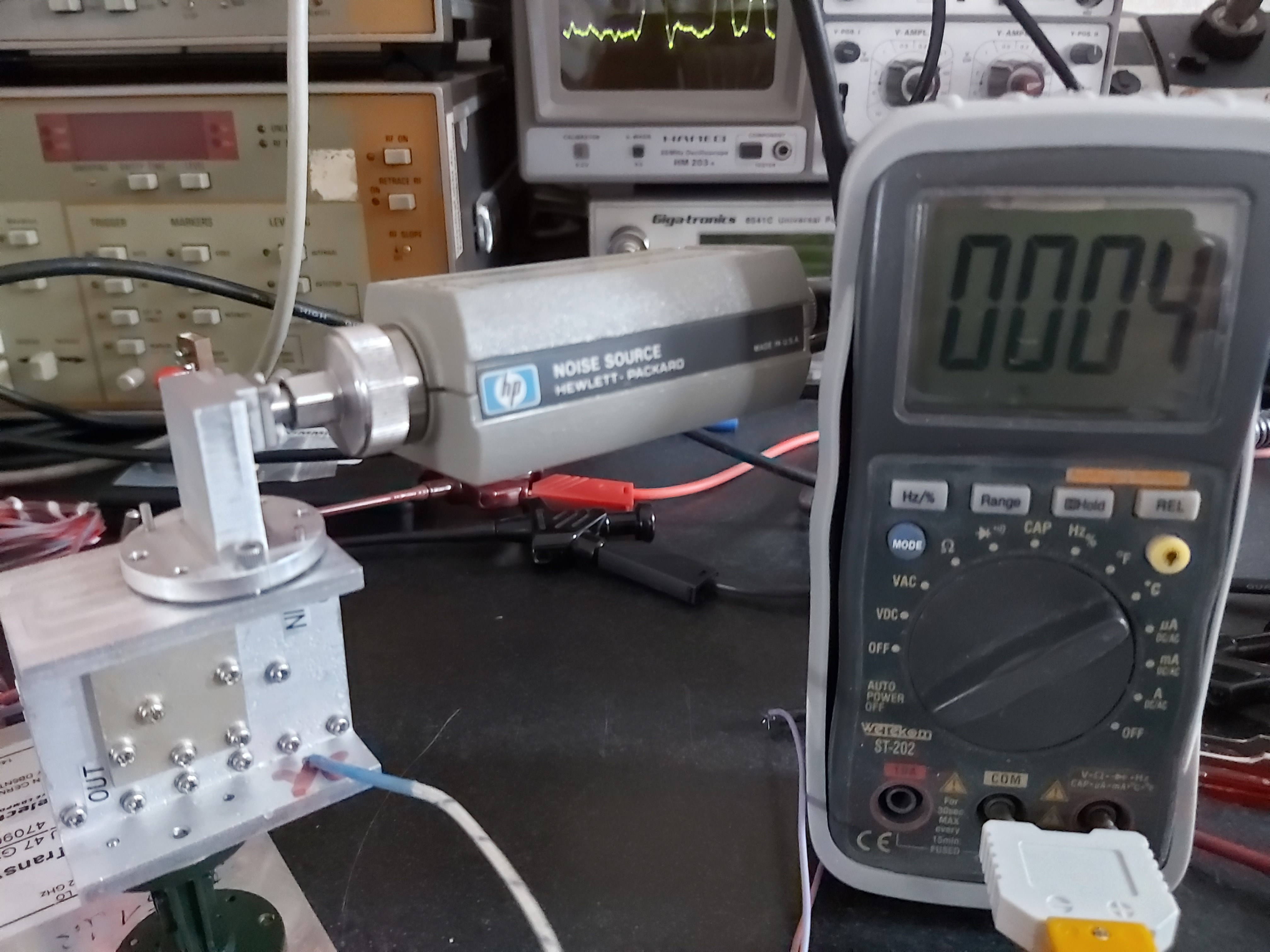
reflections at least in the WSJT echo mode. Supplement - 50 GHz semiconductor noise source IEEE: A Noise Source Module for In-Situ
Noise Figure Measurements From DC to 50 GHz at Cryogenic Temperatures Document Sections Abstract: This letter presents the design and performance of a noise source module for in-situ noise temperature measurements at cryogenic temperatures. The noise source module operates from DC up to 50 GHz and is suitable for measurements of noise temperatures as low as a few Kelvin, achieving a measurement accuracy of about ±1.2 K. The GaAs MMIC used in the module includes a well matched 50 Ω termination with better than 20 dB return loss, a heating element and an on-chip temperature sensor, hence the noise source module can directly be connected to the device under test (DUT) with no additional elements or transitions needed. The measurement can then be taken with standard noise measurement equipment. Noise temperatures as low as 13 K have been measured in Ka-band with this device. Due to the ease of use, the good matching, the extraordinary bandwidth and the less involved calibration technique, the noise source module outperforms the …. References: (1) W1GHZ Antenna Handbook; www.w1ghz.org (2) PREAMP https://www.ommic.com/product_lna/?ref=CGY2260UH%2FC1 (3) 2Watt Amp https://www.qorvo.com/products/p/TGA4046 (2 Watt@47GHz/6V – 2A) (4) 10Watt https://www.ommic.com/datasheets/OMMIC_ADI_PA_CGY2651UH-C1.pdf (5) 12Watt max. http://www.northropgrumman.com/BusinessVentures/Microelectronics/Products/Documents/pageDocs/APN318rev.pdf (GaN 11-12 Watt @ 47 GHz / ) (6) High-Efficiency Feedhorns for Prime-focus Dishes, VE4MA and Chaparral feeds with Septum Polarizers, Paul Wade W1GHZ ©2006, w1ghz@arrl.net measurements by Tommy Henderson WD5AGO wd5ago@arrl.net (7) IEEE: A Noise Source Module for In-Situ Noise Figure Measurements From DC to 50 GHz at Cryogenic Temperatures TNX DL7YC for all materials! For ok2kkw.com web edited and translated by OK1TEH |