|
The first Amateur Lunar tests & contacts |1st part: 1953-1965 On line translation needed?
The first reception of EME echo in 1944
The first EME history was written in 1944 when
first EME echoes were received on 564 MHz by German Würzmann radar
according to the article by Dr. Ing. W. Stepp. I made translation based
on what he wrote in several magazines: In January 1944 the radar was inadvertently beamed towards the rising Moon while some radar measurements were on the way. Suddenly there were observed strange series of pulses just 2,5 seconds after the transmission. This effect disappeared after a short time as Moon missed the antenna lobe. This Moon echo effect was tested during next day at moonrise time with positive result.
Source:
The first official EME test in
1946 - Project Diana
The first official European EME test in 1946 - Hungary Just one month after successful Diana EME reception - check http://www.pulispace.com/en/education/space-moon-and-the-hungarians/105-zoltan-bay-and-the-moon-radar-experiment The military use of EME propagation during 50's - 60's During 50's and 60's there were lot of EME tests, look at http://history.nasa.gov/SP-4217/ch2.htm By the way, did you know that EME could start World War 3 in 1960? check http://www.ll.mit.edu/publications/journal/pdf/vol12_no2/12_2detectsatellitiesplanets.pdf [5th Page]. The EME propagation was also used by CIA for monitoring of Soviet radars - https://www.cia.gov/library/center-for-the-study-of-intelligence/kent-csi/vol11no2/html/v11i2a05p_0001.htm.
And finally..
Lunar DX on 144 Mc! [1953] W4AO and W3GKP Bounce 2-Meter Signals Off the Moon
Listening to the wire recording from which the above graph was made, it doesn’t sound like much; a one-second beep, an interval of receiver noise, then a wavering trailing bee-e-e-e-p barely discernible in the midst of the slightly musical rushing sound that is characteristic of high-selectivity reception. You wouldn’t be impressed if you happened to hear it casually, but to Ross Bateman, W4AO, and Bill Smith, W3GKP, it was music of the sweetest sort; evidence that more years of thinking, figuring, building, re building and testing were not in vain. An amateur signal had been sent to the moon and back, at last! Bouncing signals off the moon is not new, of course. It was done on 110 Mc. by the Signal Corps back in 19461 and something approximating intelligence was sent from Cedar Rapids, Iowa, to Washington, D. C., on 400 Mc. more recently, using the moon as a reflector. These were high-power projects, however, and their slim margin of success indicated that lunar DX for amateurs was a long-chance proposition. It was an end that just might be achieved, but only after the most painstaking effort, if at all. The best available information indicated that it would take the level amateur power limit, pushed to the last watt. An antenna gain of at least 20 dB was required, and a degree of receiver performance to tax the ingenuity of the best engineers in the business was called for. Obviously, a 144 Mc. WAS, lunar style, was a long way off, but it was a challenge that a few enter prising and infinitely patient hams were bound to accept. One such ham was Bill Smith, W3GKP, then of Silver Spring, Maryland. Smitty knew what he was about, and he went at the job with no illusions about aiming his beam at the rising moon some night and then sitting back to listen to the W6s. He knew the requirements, in a general way, and he felt sure that the trick could be turned, eventually. The first step was to find a co-worker, so that the burden of equipment development and construction could be shared. A ham with a kilowatt rig and a big beam for 144 Mc. would be a fine start. Several prospects were lined up, and early in 1950 a few transmitting tests were made, while W3GKP worked on his receiving gear, but none of the prospects had sufficiently good equipment to make reception possible at that stage of the game. Other amateurs, among them W4AO, Falls Church, Va., had been working along similar lines. Learning of W3GKP’s interest, Ross joined forces with Smitty, and Project Moonbeam was on its way in earnest. Ross brought to the operation the technical know-how and the enthusiasm and perseverance Smitty had been looking for, and he had a 2-meter rig capable of a full and efficient kilowatt, a 32-element array, a low-noise receiver and a quiet suburban location. After many evenings of discussion, planning and construction, the stage was set for a series of tests with a set-up that appeared to have some chance of succeeding. The rig at W4AO was maintained on frequency precisely, and keyed in one-second pulses.
The required separation in frequency between the transmitter and receiver frequencies (to take care of Doppler effects resulting from movements of the earth and moon) had been calculated, and the receiver frequency set with elaborate stability precautions. A wire recorder was connected to the receiver output, to catch as permanent evidence any sign of a returned signal. The system was put in operation whenever the moon was in the right place, and no minor considerations like eating or sleeping were allowed to interfere. At long last, at 5:03 A.M. on July 15, 1950, came something that sounded like an echo. It was faint and indefinite, but it started at the right time and it sounded like the real thing. What was more important, it was caught on the wire recorder. It was just one tiny beep after a long series of transmitter pulses, but it was enough to keep enthusiasm going. Workers of lesser stature might have called in the press and announced their results to the world, but Ross and Smitty wanted something more solid than a single faint and somewhat dubious return on which to rest their case. Copies of the recording were mailed out to a few interested parties who could be trusted to say nothing until given the word, and Moonbeam went on and on. (A wire copy of that first success has rested in the desk of QST’s V.H.F. Editor for nearly three years.) Test after test piled failure on failure, but still the beeps were sent. An infinitesimal improvement in receiver noise figure, another decibel of antenna gain, a correction of a degree of antenna aiming error, an improved method of “reading” signals inaudible in the noise; any or all of these might tip the balance. Methods that were tried and found wanting will not be recounted here, but they were many. Moving to a new home location necessitated the dismantling of the receiving set-up at W3GKP, so Moonbeam moved its entire facilities to the basement at W4AO. In November, 1952, a huge stacked rhombic was erected and tested, and it showed a gratifying improvement over the 32-element array. A system had been devised to tie in transmitter and receiver frequencies together accurately. A new receiver front end brought the noise figure down under 4 dB. Tests on November 30th and December 3rd brought no results, so a slight modification was made in the rhombic design, to radiate maximum signal at 2 degrees above the horizon, in readiness for the next round December 27th. There were some very faint returns this time, but nothing tangible on the 30th and 31st.
Meanwhile, the staff of Moonbeam had been augmented by the addition of Ted Tuckerman, W3LZD, of Dunmore, Penna., who erected a 30-wavelength rhombic array in time for tests in late January. The receiver bandwidth at W4AO was shaved another notch for this try, too. Ted arranged to listen for the ground-wave signal with his normal 2-meter array aimed at W4AO, and then switch to the moon rhombic to try for the echo. His low-noise crystal-controlled converter and communications receiver were equipped with a super-selective 50 kc. if, system built by W3LCK. On January 23rd, this combination produced its first positive results, and a series of weak echoes was received at W3LZD, at a time when nothing was detected by the set-up at W4AO. Tests the following afternoon produced nothing, but beginning at 1533 EST on the 27th, a whole series of echoes was recorded at W4AO, two cycles of which are reproduced at the start of this article. Success, at last, and in sufficient quantity and quality to provide irrefutable evidence! The equipment used in this and earlier stages of Moonbeam will be described by W4AO and W3GKP in a subsequent issue of QST. Now the question is, “Where do we go from here?” As Smitty puts it, “This is the end of Phase A - we’ve got an echo. Phase B will be to transmit intelligence to another station. Phase C will be to work somebody, two-way. Phase D will be to break the 2-meter record. Phases E, F - well, can go on almost indefinitely. After three years we’re just getting started!” -E. P. T. 1 Kaufman, “A DX Record: To the Moon and Back,” QST, May, 1946. 2 Sulzer, Montgomery, and Gerks, “An UHF. Moon Relay,” Proc. IRE, March, 1951, p. 361.
The January success of Project Moonbeam, reported last month, was no one-shot proposition. With a fixed antenna, the opportunities for tests don’t come too often, but W4AO, and W3GKP were ready for another try on Feb. 20th, the next time the moon was in the right place. With W3GKP at the controls, a series of test transmissions beginning at 10:15 A.M. was made from W4AO. Optimum time for echoes was expected to be between 10:40 and 10:50, and it turned out very nearly that way. Many moon echoes were received at Falls Church between 10:34 and 10:53. The peak strength of the returning signals was slightly lower than in January, and fading was more rapid and violent. Up in Dunmore, Pa., W3LZD was having the best results to date. Ted’s reception of the moon-reflected W4AO signal ran from 10:37 to 10:43, reappearing briefly at 10:49. The release of information on the first successful amateur moon-reflection efforts, by means of W1AW Bulletins, nationwide ARRL press re leases, and the story in March Q has caused widespread interest in further attempts at lunar DX. Many hams, it seems, have been working in this direction; quite a few of them with a good understanding of the difficulties involved. We offer the services of this department as a means of correlating effort. If you are working on a moon project, send us the information on your equipment and schedules. If there is sufficient response, we will arrange to supply interested workers with up-to-date information by mimeo graph.
For those who would like to
know more about what it takes to bounce a 2-meter signal off the moon,
W4AO and W3GKP are in the process of compiling a comprehensive report on
Project Moonbeam. We hope to have it for you in an early issue of QST. The World Above 50Mc What is a “contact?” This question is almost as old as amateur radio, but we still have no absolute answer. If A calls B, and B replies and is heard by A, is that a QSO? It might be considered as such, if we lose sight of one fundamental fact. As amateurs we are presumed to be engaged in communication. This implies exchange of information, not just identification of one another. Thus, a reasonable definition of a QSO, for amateur purposes, would seem to be an exchange of useful information. Otherwise, why communicate at all? Mutual exchange of information has become the basis for determining whether a contact has been made, and it has served this purpose well in all sorts of situations. It is the basis for awards issued by ARRL and all other amateur societies. The minimum exchange for two-way work to be considered a contact has been fairly well standardized on a two-stage procedure: positive identification of calls at both ends, and the complete exchange of signal reports. The latter is about the shortest item of information that can be transmitted between two stations that will have any meaning at all. The form varies with various operating activities, but the basic idea of mutual exchange remains in all. The reason we go into this here is that the question arises frequently in marginal forms of v.h.f. communication such as meteor-burst work. Here the additional point of total time involved enters the picture. Should there be a time limit for the completion of the exchange? Could you start this morning, get part of the information through, and complete the exchange tomorrow, or next week, for example? Is it reasonable to spread the exchange over a period of a couple of hours, when only the basic elements of a QSO are involved? The answer to these questions is bound to be arbitrary, to some extent. We must have some sort of standard. Here is the one we have set up for marginal communication, to determine whether or not a QSO has taken place. We feel that it may well be applied by v.h.f. men in judging their own efforts and results. First the basic minimum of identification and exchange is a must. You call. The other fellow answers. If you positively identify him, and establish that he was coming back to you, you send a signal report. (More on that later. ) If he gets the signal report, he then sends you one. If you get it, you send “ R.’‘ If he gets the single letter, he also sends ‘‘ R, ‘‘ and the QSO is over, as far as the claim for a contact is concerned. There is no obligation to hear or send closing 73, or SK, or confirmation of either of these items. You send the SK, of course, as the indication for other listeners that you’re through, but you don’t have to exchange SK’s! How the exchange is made can be arranged to suit your own operating preferences. If it is handled in random fashion it may be a very long drawn-out matter, in meteor-burst communication on 144 Mc., or even in ionospheric-scatter work on 50 Mc. Precise timing of transmissions at each end expedites the exchange no end. Using clocks checked carefully against WWV, you call the first minute, or whatever prearranged period you prefer. If your co-worker on the sked hears you, he calls for the next period. If you identify him calling you, you reply with the signal report. If you haven’t identified him completely, you call again. Assuming that you did identify him, and sent the report next, you keep sending it every time it’s your turn, until you hear him send a report. If you copy the report, you send the R. When you hear his R you’ve got your new state, ARRL section, or whatever. What kind of signal report? Go through the meaningless RST, if you like, but we suggest the S-code for meteor-shower work. This means something, if used properly. S1: short bursts, with no copy. S2: bursts long enough to identify at least individual letters, and up to 5 seconds’ duration. S3: bursts of 5 to 15 seconds. S4, fairly rare in meteor-burst work on 144 Mc.: 15 seconds to 2 minutes. S5: 2 minutes or more of solid copy. Lest the inexperienced be dismayed by this reporting system, let it be said that plenty of good meteor-burst contacts have been made with nothing better than S3 reports. A lot of information can be sent on c.w. in bursts of 5 to 10 seconds. Note that R has no place in the signal reporting. It is reserved for the “R R R R R R R-" you're going to send to indicate that you have copied the necessary information. A variation of this form is often used in ionospheric-scatter work on 50 Mc. Here the duration of bursts is longer, and they are usually super-imposed on a very weak steady signal. So an RST is sent, with the R indicating the percentage of time the signal is heard. R1: up to 20 per cent. R2: 20 to 40 per cent. R3: 40 to 60 per cent. R4: 60 to 80 per cent. R5: over 80 per cent, or “in solid.” The S part of the report is the maximum strength observed, on the usual S scale. The T is as in the conventional RST system. Sounds complicated, but it isn’t when you get the habit - and it is an informative report. So is the S system used in meteor work. Either kind of QSO certainly qualifies as such, in that it provides a useful exchange of information. Either means far more than the DX man’s standard 579, given to a 14-Mc. rare one when the latter is probably working six other people! How long? So long as it is a continuous effort, only the endurance of the two participants matters. Many acceptable claims for new states worked on 144 Mc. have been made on the basis of work that took two hours or more. We’ve had no instances of anyone counting part of an exchange from one day and another part the next, but if that should come up we’d feel required to turn thumbs down! The role of the tape recorder? Recording for demonstration later, and for posterity, is fine. We’re all for it. But if you have to play back a recording to see if a contact has been made, you haven’t made one. You must copy information, and know that you’ve copied it, before you can truthfully send the “R R R R R -“ that will conclude the QSO. QST March 1957 Satellite Tracking Minitrack Calibration by Moon-Bounce Signals The antenna system for a satellite tracking installation has to be calibrated on an actual signal if the highest possible accuracy is to be achieved. Various calibration methods have been proposed and used from time to time, ranging from air planes and balloons carrying 108 Mc transmitters on special flights to using radio “stars” (QST, April, 1957) as the calibration-signal source. Now, in a joint announcement from the Naval Research Laboratory and the U. S. Army Signal Engineering Laboratories, it is stated that signals reflected from the moon have been used successfully for Minitrack calibration. Far from being just a stunt, moon-reflected signals offer a practical way of covering a large portion of the Earth’s surface, and plans are under way, for making “moon-bounce” a primary source of calibration for Minitrack stations. To this end a high-power 108 Mc transmitter is being constructed and should be undergoing testing by the time this appears in print. The NRL SEL experiments were carried out with SEL’s “Diana” transmitter, which would not be usable for calibration of a regular Minitrack installation because Diana’s frequency is 151 Mc. Special receiving equipment designed for the latter frequency was used in the NRL-SEL tests, but the output and recording circuits were of the regular Minitrack type. It is expected that when the 108 Mc transmitter is in operation - the target date is October - its transmitting schedules will be made available to operators of Mark II Minitrack installations.. If practicable, they will be published in QST. Whether or not you can participate in the satellite-tracking program, a good 108 Mc converter will give you a start toward hearing signals both from the Earth’s most prominent natural satellite and from the man-made “moons” to be launched during the coming year. QST September 1957 Want a Moon QSL?
September QST [1957] (page 31) mentioned that a high-power 108 Mc transmitter was being planned for bouncing signals off the moon, with the object of providing a satellite signal for calibrating Minitrack antennas. Procurement problems caused some delay in getting into operation, but the big (50 kW) transmitter got its first workout on the evening of December 3. We understand that it put a good signal into NRL’s Blossom Point, Md., tracking station via the moon. The moon-reflected signal also was heard at W1CUT and possibly by other amateurs who had the necessary receiving equipment and heard the special bulletin put out by W1AW early that evening. Transmission schedules are highly tentative but, subject to probable change, the periods January 4 to 16 and February 28 to March 12 have been picked. The transmissions will consist of a continuous unmodulated carrier, interrupted for one minute beginning exactly on the hour and half hour. The transmitter will not necessarily be on the air the whole time the moon is visible on these dates. W1AW will carry special bulletins on the transmissions whenever lastminute information becomes available. The transmitter is located at the U. S. Army Signal Engineering Laboratories in Fort Monmouth, N. J., and works into a 60 foot “dish.” SEL is interested in getting reports from amateurs on the moon-reflected signals and plans to get up a moon-bounce QSL card to verify reception. Reports should be sent to ARRL, West Hartford, Conn., not to SEL, and should include exact times, strength of signal, and any peculiarities such as type and depth of fading. Another good reason for getting a receiver on 108! QST ?1958
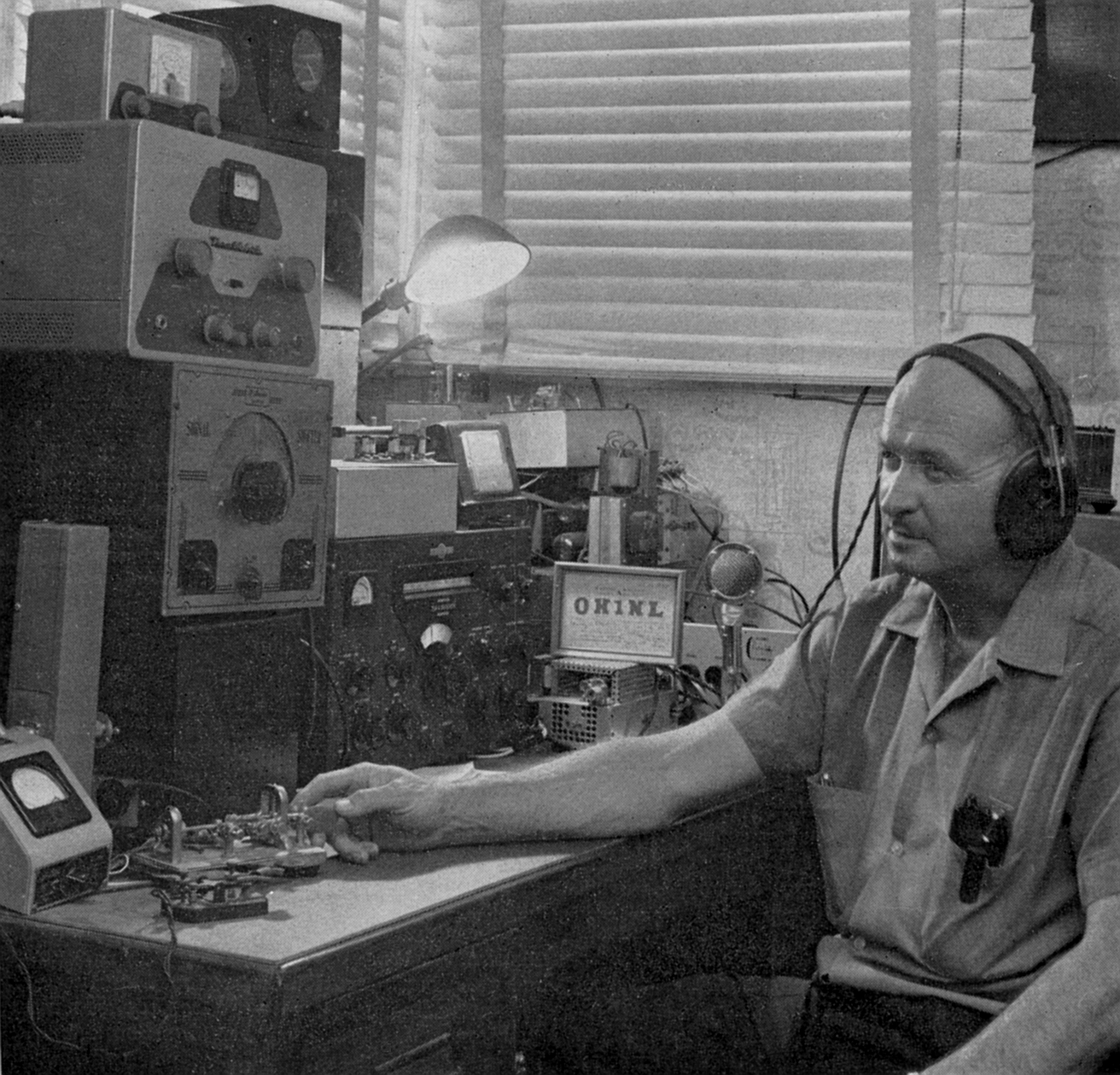
CQ 1296 MOONBOUNCE DE W1FZJ! On 1296 mc these days Sam Harris, W1FZJ of Microwave Associates, is receiving his own echoes loud and clear from the moon. Soon, an exciting new chapter in amateur communication will open when two amateurs become the first to QSO on the Earth-Moon-Earth circuit. Sam’s moon contacts are being made with a powerful one-kilowatt transmitter. It consists of a high stability 9 mc crystal oscillator - multiplier chain driving an Eimac 4X150A multiplier to 432 mc. and an Eimac 2C39A tripler to 1296 mc. With 30 dB gain, the power amplifier stage is an Eimac 3K2500LX klystron running at one kilowatt driving an 18 foot dish which tracks the moon across the sky. The multiple conversion receiver at W1FZJ employs a Microwave Associates MA-2-1000 Parametric Amplifier having a noise figure of less than 2 dB. Nominal receiver bandwidth is 100 cycles, with the choice of an additional “moonbounce” 35 cycle passband. With the coming of successful 2 way amateur moonbounce communication, Eimac tubes are once again contributing to a major amateur radio breakthrough.
QST August 1960 "It Seems to Us..." - NEW FRONTIERS
The saga of amateur history is exciting, and our past is studded with outstanding technical and operating achievements. Hardly a month goes by without there being some new event which emphasizes the excitement of amateur radio and points out that there are, forever, new fields to conquer. Such a month was this July. It was a month of new records on u.h.f., punctuated with re ports of near success, and then final achievement. It was the sort of month that throws copy deadlines all askew, but for good reason. The first intimation that something was brewing came on Sunday, July 17, when W1HDQ was helping time a sports-car rally, but had sort of a preoccupied air throughout the proceedings. Not until the next day at the office did he confide that he had been tipped off that W1FZJ had succeeded in bouncing 1296 Mc signals into W6HB’s setup in California and that a two-way exchange was in the offing. By the middle of the week we were getting more details, but the real news was that signals had been bounced both ways off the moon between east and west, on 1296 Mc. Imagine - two-way transcontinental communication on 1296 Mc! Such frequencies are ordinarily thought of as being useful only from one side of town to the other, yet these fellows had talked with each other clear across the country, with the signals actually travelling a half a million miles in the process. Few people, indeed, in this world have had the privilege of participating in such an historic event; our hats are off to W1FZJ, W6HB, and all the others who took part so successfully. But wait! This was not the only exciting u.h.f. news of the month. Right in the middle of all the 1296 Mc hubbub came word that KH6UK and W6NLZ had done it again - this time the Pacific had been spanned, on 432 Mc. The signals of KH6UK were heard loud and clear in California, and only some local receiving difficulties at KH6UK prevented this from being two-way between the Mainland and the Islands on 432 Mc. It is this sort of achievement which helps write the record of amateur performance in the public interest. In 1944 the Federal Communications Commission held extensive hearings covering the entire frequency spectrum, requiring each radio service to appear and present its case justifying continued use of the public domain of the frequency spectrum, plus new assignments in the v.h.f. region and above. At that time the League, on behalf of the amateur radio service, said (in part) concerning the territory above 50 Mc.: “You will understand our immense enthusiasm to get hold of the very high frequencies and the superhighs after the war. It has been the constant history of amateur radio that its pioneers explore and open new territory at successively high-frequency frontiers for the use of the amateur body generally and to the benefit of the whole art. We want a chance to apply, to the problems of amateur communication at such frequencies, some of the new knowledge born of this war. Although there has been a great increase in man’s knowledge of such frequencies in the last few years under the impetus of military necessity, we can be certain that the surface has hardly been scratched, that much work remains to be done, that there are untold treasures to unearth to the subsequent benefit of man kind. This art definitely needs the application and ingenuity of the amateur in this part of the spectrum.” Amateur achievements in July, 1960, are simply an unusually-spectacular example of the foregoing principle. We are not so naive as to argue that the amateur service pioneers in technical developments today in the same way and to the same extent as in the earlier development of the lower frequencies; the complexity and expense of microwave gear handicaps the great majority of amateurs and prevents our service from “competing” on an equal basis with the billions of dollars now being poured into research of the upper reaches of the spectrum. But no amount of money can buy “the amateur spirit in research,” that lively curiosity which often transcends a mere professional call to duty, and which was certainly the inspiration behind the W1FZJ - W6HB and W6NLZ - KH6UK feats. It is that heart-interest in the art which is carried by radio amateurs from their own avocation to all the other fields of radio, and can be said to be the fundamental reason for America’s leadership in technical electronics. W1BU and W6HB Make First Amateur Lunar QSO Coast to Coast Via the Moon on 1296 Mc.!
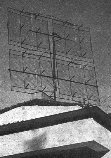
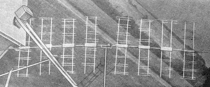
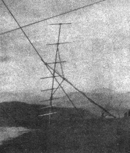
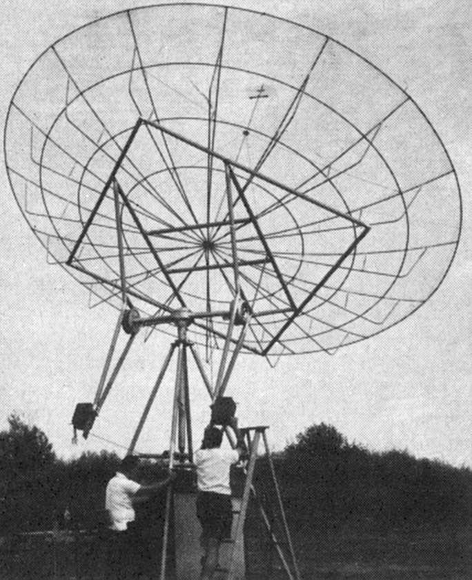
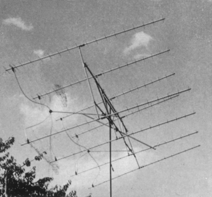
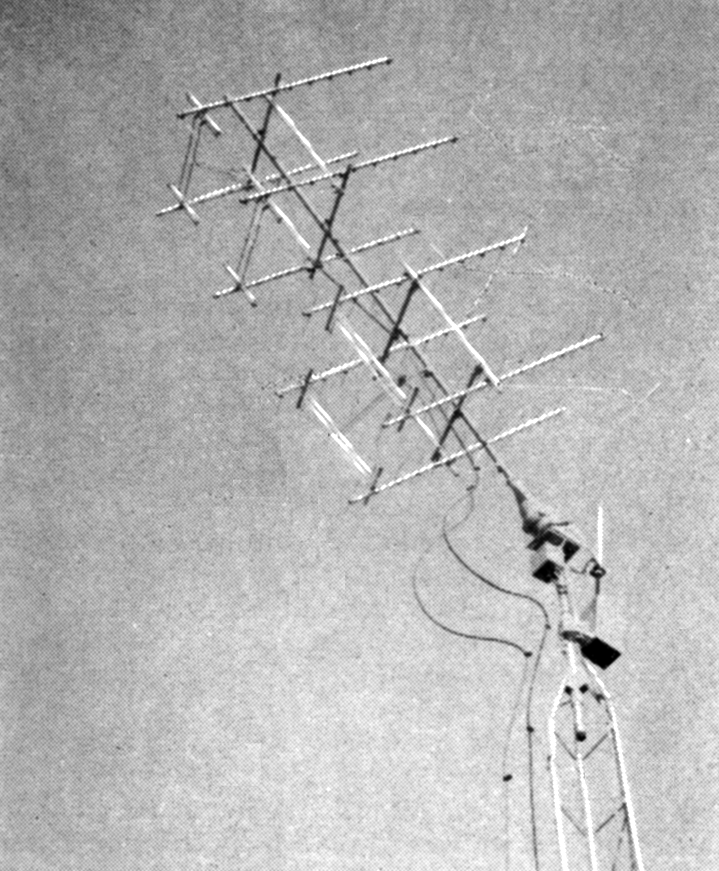
Sam had been at it for years. Several tremendous arrays had been erected above and amid the pines at Medfield in an attempt to make a moon- bounce contact on 144 Mc. Echoes of a sort were recorded several times, but even with a huge 128 element array rigged with an ingenious system for tracking the moon the returns were discouragingly weak, and few and far between. After end less hours of back-breaking labor and patient testing, the gang at W1BU sadly came to the conclusion that if a lunar QSO was to be made the work would have to be done all over again, on a higher frequency. The logical frequency for the new effort appeared to be 1296 Mc. Here it is now possible to achieve truly low-noise receiver performance, and efficient operation of a 1kW transmitter is practical. With a parabolic reflector of reasonable size a beam sharp enough for moon-reflection work is within the realm of practicality for amateurs. Work toward this end was begun by W1BU about a year ago. The problems were many, all revolving around the need for high stability and accuracy in several fields. If you are to have more than a few minutes in which to conduct tests, the antenna array must track the moon. You don’t just aim in the general direction of the moon and blast away, hoping for the best; you rig up some kind of automatic system that will put your beam squarely on the moon and keep it there, for hours. To get the needed sensitivity in the receiver you go to a bandwidth of 100 cycles or less. This means a high order of precision in several departments, and it imposes stability problems most amateurs have never dreamed of. Before you dash out to your corner radio store for the necessary parts, you first solve a whole batch of thorny mechanical and electrical problems. Then you work, work, work - and work some more. There are probably few amateurs with the financial resources needed to build and operate a 1296 Mc moon-bounce station, and if there are those who could afford it they would need help to perform the physical labor involved. Thus, moon bounce becomes an ideal project for an ambitious radio club group, and the first lunar QSO resulted from two such cooperative efforts. The Rhododendron Swamp Vhf Society had a backlog of experience with big antennas. They also had access to considerable scientific equipment and know-how. The 18 foot parabolic reflector (D. S. Kennedy Co.), the 1296 Mc parametric amplifier (Microwave Associates), and the kilowatt klystron amplifier (Eimac) were “promoted.” But that still left a vast amount of construction of typical ham make-do style, and plenty of man hours and foot-pounds of labor. A high-stability exciter and the necessary moon-tracking antenna mount and drive had to be designed and built, as did the 1296 Mc converter and 1000 cycle and 100 cycle filters for the receiver.
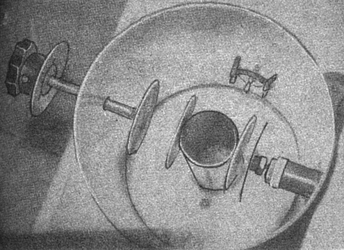
Somehow this was finally done, with results somewhat as shown in our pictures, and by the end of May, Sam was able to announce that the W1BU moon-bounce station was working - and receiving its own echoes consistently for hours on end. Now, who would match the effort so that actual communicating could be tried? The challenge was picked up by O. H. “Hank” Brown, W6HB, of Eitel-McCullough, Inc., San Carlos, Cal. Rallying members of the Eimac Radio Club, Hank put them to work on a crash program aimed at making the first amateur moonbounce QSO, and incidentally a new 1296 Mc DX record. The Eimac group were ready for their first test July 17. Moonrise was at a most inconvenient time, but that didn’t hold the gang at W6HB back. Tests were started as soon as the moon was above trees and power wires, or about 0200 PST. Almost at once, Sam heard the signal from W6HB, weak and barely discernible in the noise, but a signal other than his own, at last! Then followed three hours of testing both ways, with the telephone line across the continent busy all the while. Reception at W1BU was considerably better than at W6WB, due at least in part to the use of a 100 cycle filter at W1BU. When Sam switched to 1000 cycle bandwidth there was little or nothing to be heard of W6HB. Communication was only partially successful for two reasons: the signal at W6HB was just too weak to copy, and keying of the transmitter at the western end moved the frequency just enough so that it slipped out of the passband at W1BU. With 100 cycle selectivity, that can happen even when little or no frequency shift is audible on the beatnote. Several weak spots were turned up by the first test. The dish at W6IIB was scrounged from surplus; it was rusty and in none too good condition otherwise. Before the next test it was coated with aluminum foil obtained from a nearby grocery store. Perhaps more important, the 100 cycle filter was added in the receiving setup. Tests were set for July 21, beginning at 0600 PST. The moon had been clear before, so the simple sighting-tube method had been quite satisfactory for lining up the W6HB dish. This time there was fog, and furthermore the moon rose close to the sun, making visual sighting extremely difficult. Finally they were lined up, and transmissions began at W6HB. The signal came through immediately at W1BU, peaking some 8 dB above the noise level, though with a rapid flutter fade which made copy extremely difficult.
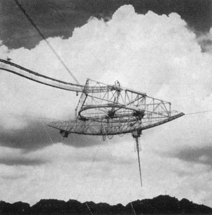
Using a 3 letter code for
“no signal, some signal or good signal,” reports and calls were exchanged,
and the first two-way amateur communication via the moon was history. - E.
P. T.
Who was Sam Harris, W8UKS/W1FZJ/W1BU?
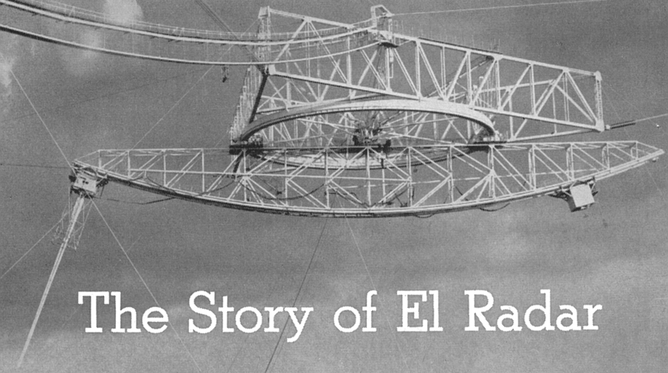
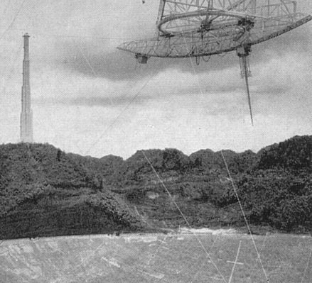
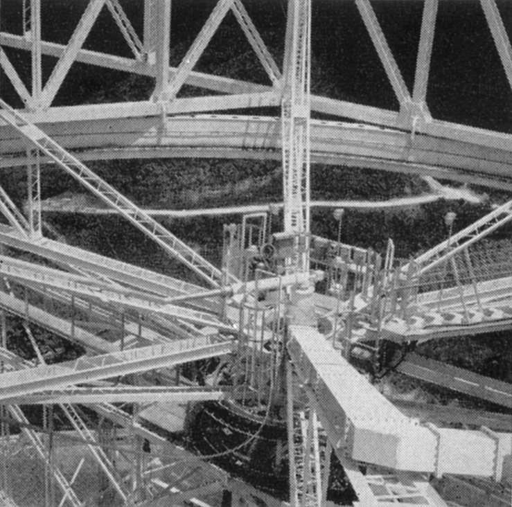
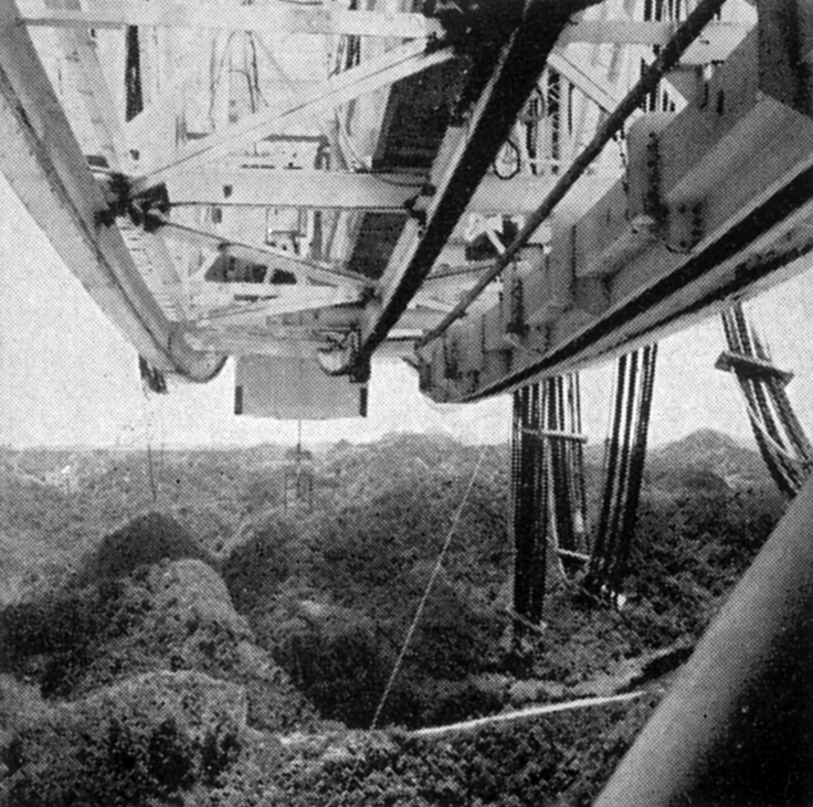
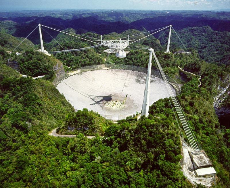
He put up antennas bigger, better, higher than anyone. His receiver front ends pushed the amateur state-of-the-art for years. He was the prime mover in the first successful assault on that Mount Everest of the world above 50 megacycles - two-way communication by way of the moon. Sam never undertook a project at less than full-steam ahead. His extraordinary dedication to the achievement of seemingly impossible objectives, brought him the enthusiastic cooperation of scores of avid vhf enthusiasts. Visitors to the Harris hideout in the pine woods near Medfield, MA, tended to get short shrift unless they came prepared to work, in which case they might well end up members of the legendary Rhododendron Swamp VHF Society, builders and operators of W1BU. Large waves emanating from big antennas at W8UKS, Lorain, OH, signalled the appearance of Sam Harris on the vhf scene in the late 1940s. His City Slicker array describing a novel and effective system for feeding large phased arrays marked his first appearance in QST, out side the activity reports in the undersigned’s vhf column, “The World Above 50 Mc.” He compiled the vhf coverage in CQ for several years, until he took over the same job for QST (at this writer’s request) in the summer of 1960. Fittingly, the first Harris vhf column appeared in the September 1960 issue, which featured a cover story on one of the most significant Amateur Radio news events of all time the first two-way amateur communication by way of the moon. This almost unbelievable feat was pulled off on 1296 MHz, rather than on 144, where EME efforts had been concentrated up to then. It was no accident that Sam was tapped for an important role in the operation of the 1000 foot hemispherical reflector and associated radio astronomy equipment at Arecibo, PR, in 1965. Nor was it a great surprise to most of us that this superb plant was put into service briefly on 144 and 432 MHz, on two occasions, soon thereafter. Characteristically, it was not long before a smaller version of this great array began to take shape over the garden that Helen, W1HOY, had started in their backyard in Arecibo. That it never quite reached the heights of many previous Harris antenna ventures is the sad part of this story. A series of hospitalizations that began some two years ago finally resulted in the passing of one of the true greats of Amateur Radio on November 6, 1978. It is utterly impossible to tell the Sam Harris story in a few words, or to understand fully his impact on our world, unless you knew him well and had the opportunity to observe him at work on a favorite project. Surely, he was a classic example of the kind of person who becomes “a legend in his own time.” Hiss Amateur Radio career will be a source of inspiration as long as vhf enthusiasts gather to relive great moments in their branch of the communications art. The World Above 50 Mc. was a better place for all of us because he was such a big part of it. Aside from his wife W1HOY, he leaves a son, Pat, W1HIV, and. a daughter. - W1HDQ (QST January 1979)
Project Moon Bounce
The Story of the First Successful BY WILLIAM ORR, W6SAI
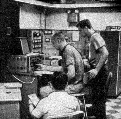
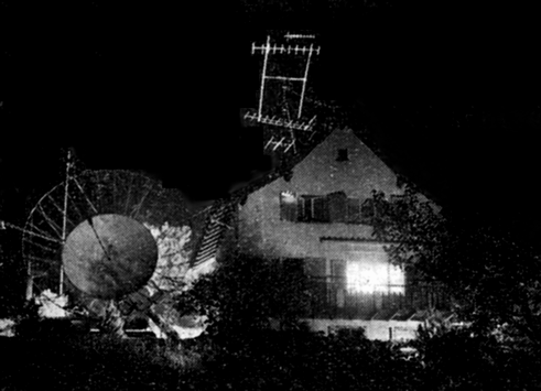
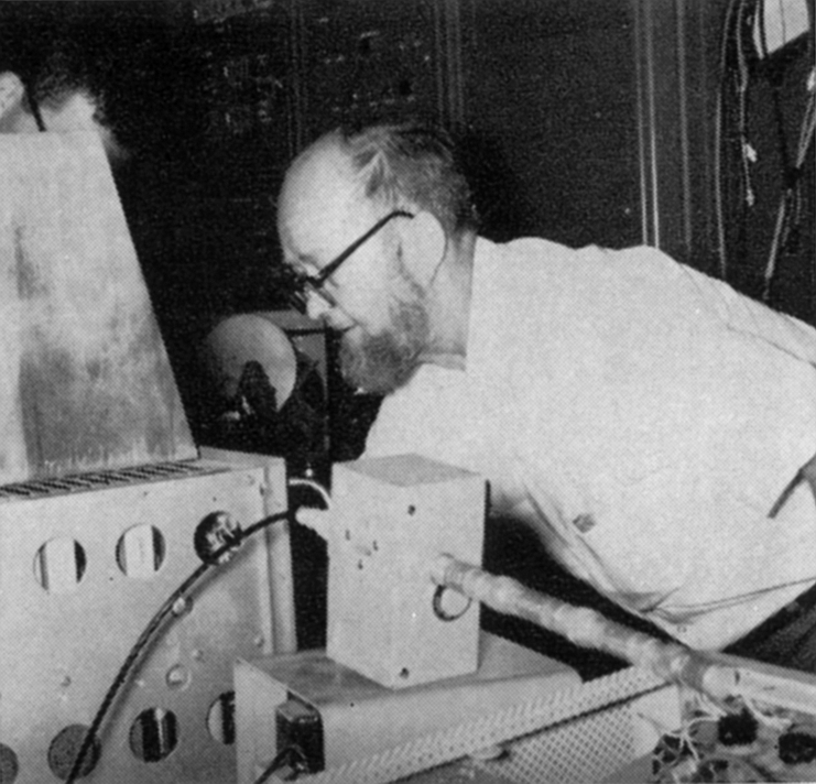
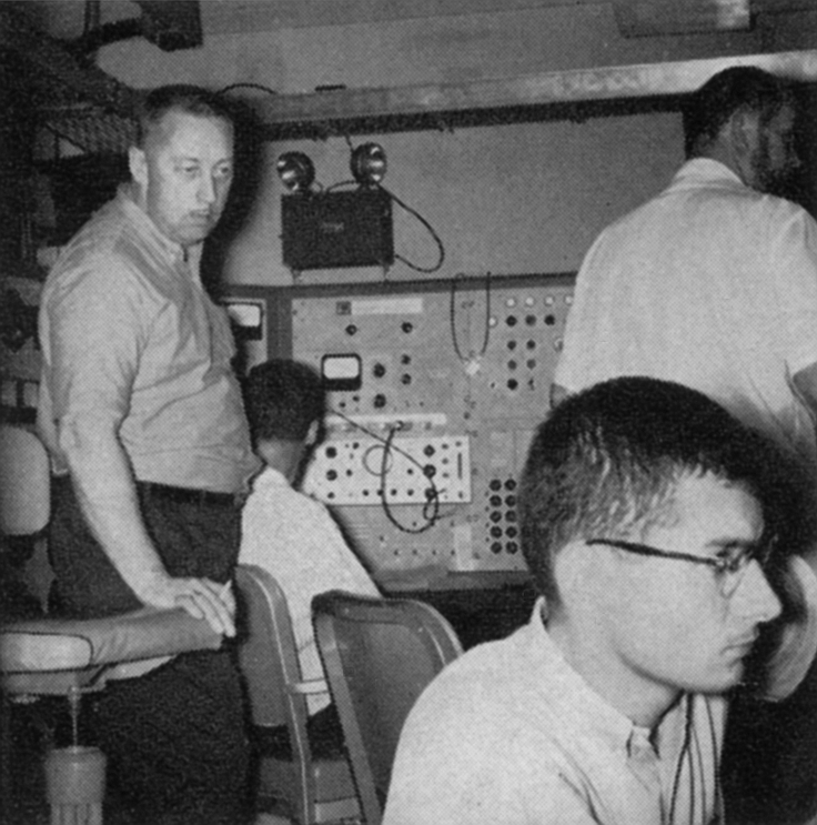
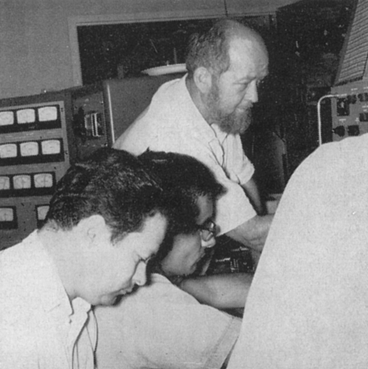
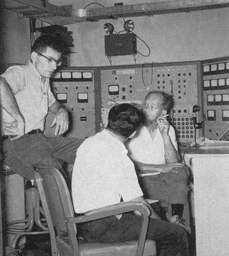
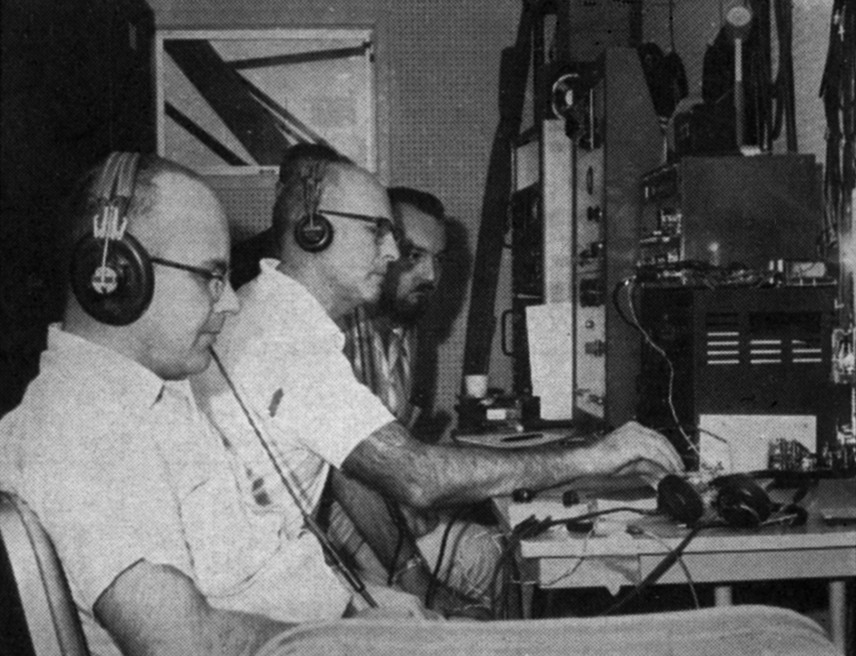
Now, in the cool, silver light of the waning moon, the parabolic antenna looms above the clustered amateurs. It is 0145 Pacific Daylight Time, July 17, 1960, and the participants in the forthcoming drama are not quite awake and only dimly thinking of the historic event soon to happen. It is a quiet time, breath less and serene. The hams (they are all active amateurs and DX enthusiasts) cluster around the two small wooden buildings and the dish antenna, sitting forlornly in the middle of the empty lot in a corner of San Carlos, California. Behind them, the town is asleep, bathed in the glow from the moon, floating large on the horizon. Quickly the amateurs move to the task. The doors to the buildings are flung open and the interiors are illuminated by the harsh overhead bulbs. The buildings are filled with electronic equipment. The hum of conversation grows and a thermos jug of coffee is opened. Equipment is now running, and a nervous tension is felt by the operators. Is everything working properly? Anxious eyes scan the meters, and two hams struggle with the receiver. One fellow takes a pencil from the table and scribbles on the ply wood wall of the receiver shack: “July 17, 1960. First 1296 Mc. moonbounce transmissions to W1FZJ from W6HB start approximately 0200 PDT.” The equipment is adjusted once again and the u.h.f. klystron springs into life. Willing hands align the dish on the waiting moon. The small test oscillator atop the receiver is monitored loud and clear at 1,296,001 kilocycles. The transmitter is tuned and ready... Across the continent in Medfield, Mass., a second body of amateurs is grouped about a large parabolic dish and a confusion of u.h.f. equipment. The area is covered with recorders, parametric amplifiers, a klystron and its exciter, a sensitive i.f. strip, and various exotic audio filters. As the equipment is brought into tune, the telephone on the operating table rings. The nearest ham scoops up the receiver and listens intently. After a pause, he motions to the others: “The California gang is transmitting to us! You’d better crawl into that receiver and start listening!”
The door to a new concept of amateur communications was flung open on this eventful morning in July, 1960, when the first successful trans-continental moon-bounce test in amateur history took place between the members of the Rhododendron Swamp VHF Society (W1BU) of Medfield, Mass. and the Eimac Gang Radio Club (W6HB) of San Carlos, California. In an instant of time old u.h.f. records and concepts were shattered and swept away, and new, exciting fields were laid open. It was truly a red-letter day for amateur radio! Two-hundred and thirty-eight thousand miles to the moon and back! No wonder the W1BU gang nearly split W6SAI’s ear-drum over the telephone line: “Keep sending! We hear you!” The Beginning The amateur u.h.f. moon-bounce story started innocently enough at the time the new Eitel McCullough plant in San Carlos was dedicated in April, 1959. The idea slowly evolved that it would be newsworthy if the plant could be opened by a radio pulse reflected to California from some distant point via the moon. Finally, through the kind assistance of E. Finley Carter (K6GT), director of Stanford Research Institute, a 10 kilowatt 440 Mc transmitter located at College, Alaska, equipped with a sixty-foot parabolic “dish” antenna, was made available for the moon-bounce exhibit. Suitable receiving equipment for the California end was built by Granger Associates, Inc. of Palo Alto, California. The grand opening went off without a hitch! The Eimac hams were amazed at the strength of the 440 Mc moon-bounce signal! It all looked so easy! W6HB instantly decided that the accomplishment could be duplicated on an amateur level. In his spare time Hank figured that it might be possible to turn the trick on the 1215 - 1300 Mc amateur band. A good low-noise “sky window” was available in this frequency region. In addition, only a medium-sized dish would be required, and production tubes were available for this band which would run a full kilowatt input for amateur service. The project received a tremendous boost when Walt Morrison, W2CXY, contacted Hank and told him of East Coast interest in the under taking. Accordingly, several Eimac u.h.f. transmitting klystrons were modified to reach a frequency of 1296 Mc and one was shipped to Walt, and another to Sam Harris, W1FZJ. Shortly thereafter, Sam and Dana Atchley, W1HKK, offered their assistance, which included the loan to W6HB of a brand-new Microwave Associates parametric amplifier! The prospect of a receiver having a noise figure of less than 2 decibels provided the necessary boost in morale, and W6HB enlisted the efforts of Willy Sayer, WA6BAN, to assemble sufficient equipment to set up the west coast terminus for the proposed moon-bounce link! Problems, Problems, Problems!
The problems were staggering! Where to get a microwave dish? How about the antenna feed system? Frequency stability: How much is required? Hank still shudders when he thinks of this roadblock to progress: “A frequency shift of one cycle at the fundamental frequency of one megacycle results in a shift of 1296 cycles at 1296 Mc. If W1FZJ is listening for us with a 100 cycle passband, he’ll be looking for a needle in a haystack if we can’t hold our 1296-Mc. frequency within 50 cycles or so of where we plan to be!” How do you key a transmitter and yet have less than one cycle of keying chirp reflected back to the oscillator? The Eimac Gang Effort The project was “getting hot” by now! W1FZJ was just about ready to go on 1296 Mc. During the early days of June protracted discussions took place between Hank, Willy, and Bill Orr, W6SAI, and it was decided to gather all the bits and pieces of 1296 Mc gear in one place and turn the whole project over to the tender mercies of the Eimac Gang Radio Club, working under the supervision of SAT. In addition, Bill Eitel, W6UF, and Jack McCullough, W6CHE, generously allowed use of the area which has been set aside for various projects of the Eimac Radio Club for the installation of the equipment in the two plywood buildings owned by the Club; and further permitted the Club to use the facilities of the sheet metal shop and the welders (a u.h.f. must!) in order to get the program off to a flying start. The Club was divided into teams. Bob Sutherland, W6UOV, supervised the receiver team working under Ray Rinaudo, W6KEV, and the antenna team working under Al Clark, W6MUC. The transmitter project was directed by George Badger, W6RXW, and the exciter chain was developed by Willy, WA6BAN. A three-week deadline was set by slave-driver W6SAI and the fur began to fly! As time went by, it became apparent that the exciter could not be completed in time, so an SOS was sent out to Mike Krivohlavek, K6AXN, requesting the loan of his record-breaking 50 watt, 1296 Mc transmitter. Mike responded immediately, bringing his exciter and his one-megacycle crystal oven. The tempo increased, with the gang working into the small hours of the morning until finally - late Friday evening, July 15 - everything seemed to work perfectly. A telephone call was put through to W1FZJ, arranging for a schedule starting at 2 AM. Sunday morning, July 17, a time at which the moon would be in full view on both the East and West coasts. The hardest and most nerve-wracking part of the project now began - standby and wait! Results of the Tests
The Eimac Gang’s transmitter consisted of an oscillator-multiplier chain driving 2C39A/3CX-100A5 multiplier stages which provided a level of 20 watts or so at 1296 Mc. This exciter drove a DK2500LX klystron, whose cavities had been modified to tune across the 1215 Mc amateur band. Running one kilowatt input, it was possible to obtain 400 watts or so of output from the klystron amplifier, whose efficiency was some what limited by the modifications made to the external cavities. (See the block diagram on p. 11.) It was only a few minutes after the transmitter was energized and the rusted eight-foot dish was aimed at the moon that the gang at W1BU/W1FZJ first heard the California signal. The historic moon-bounce signal was just above the noise level, and disappeared coyly after a few seconds. Sam tuned his receiver frantically and after a few breathless moments found the signal once again. Yes, the signal was audible: it was right here on the dial. “Tell ‘em to key the carrier,” Sam yelled to Sandy Watson, W8FRA, who was standing by at the telephone link coupling Medfield with San Carlos. After a time lag of a few seconds the weak, wavering carrier disappeared for good. It was lost! “Tell ‘em to stop keying and give me a steady carrier!” After frantic circuit adjustment, Sam found the carrier once again, wavering between the noise level and 2 decibels above it. “I think you have enough keying “yoop” to go right through my passband,” exclaimed Sam, as he took over the land-line. “In addition, I think there’s a minute amount of instability in your oscillator, and the crystal is being vibrated by people walking around your shack. Can’t you do something about it?” The information was hastily relayed to George, W6RXW, who turned off the klystron power supply and dashed from the tiny shack. He returned triumphantly in a few moments, waving a cardboard box and a huge slab of fibrous packing material, scrounged from a nearby waste can! The oscillator was hurriedly mounted on the spongy packing material, and the cardboard box was dropped over the haywire assembly. “You guys get out of here and take your big feet into the receiving shack,” ordered George! “I’ve got to keep vibration down to a minimum!” Sure enough! The added stability was sufficient to keep the moon-bounce signal within the razor-sharp passband of the Medfield receiver. “Sam says he wants us to listen to his transmitter,” said Hank, who was on the San Carlos end of the land-line. With a sweep of his hand, RXW killed the klystron supply and the exciter, and said, “Will the coaxial switch gang swing into action?” This joking remark referred to the fact that transfer of the coaxial transmission line from the transmitter to the receiver was accomplished by two club members, armed with box wrenches. The large u.h.f. coaxial fitting had to be taken apart, the transmitter section cast aside, and the receiver section bolted in its place. This task took fifteen minutes or so, and was invariably accompanied by skinned knuckles, banged fingers, and sulfurous language. Armed with a tool box KEY and UOV advanced upon the offending connection, stating they would be willing sacrifices to the good of amateur radio!
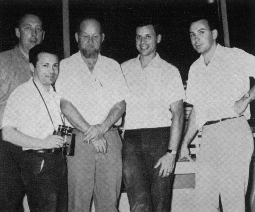
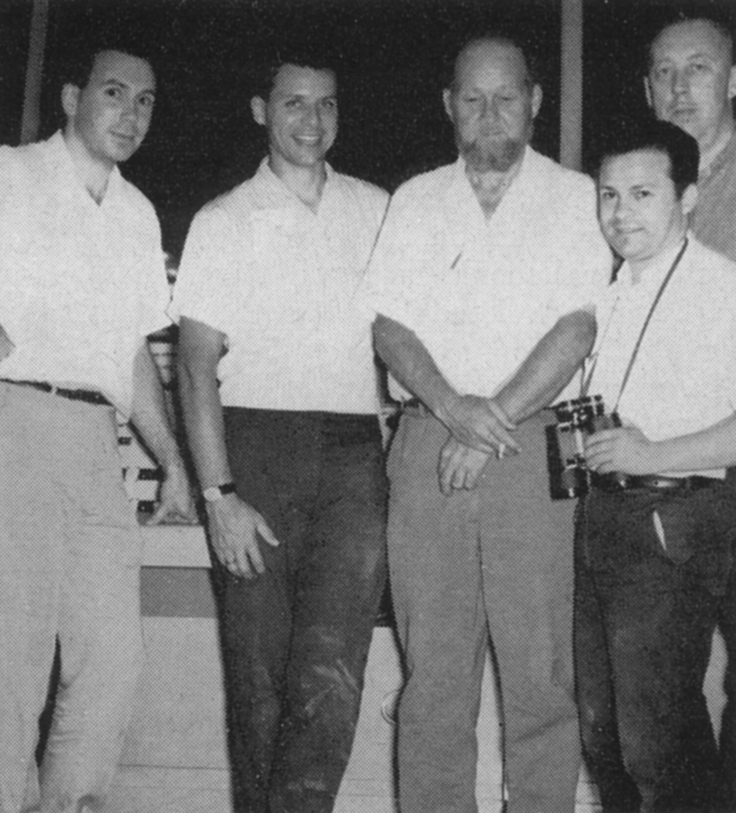
“I’ve figured out that - considering the peewee dish and our 500 cycle passband - we just barely won’t hear him,” muttered W6UF as he anxiously watched Ray play with his magic box. “I hope I’m just being conservative.” After an eternity Ray straightened up as if he had been electrocuted by a bolt from the heavens. “I hear him!” he shouted. W6HB grabbed the extra phones lying on the table and listened intently. He heard the rushing background noise, trans formed into a bell-like song by the action of the audio filter. Nothing happened. The onlookers held their breath, and the tension grew about their shoulders. Suddenly Hank and Ray broke into broad smiles and shook hands. “Congratulations, Ray,” said Hank, as he removed the phones from his head and handed them to the next eager listener. W6HB slowly walked to the telephone to tell Sam the good news. Yes, the W1BU signal was being heard in California. True, it was unbelievably weak, being in the noise for a majority of the time. Miraculously, the signal would on occasion rear above the enveloping background noise and bits and pieces of Sam’s slow-speed c.w. could be read The first east-west 1296 Mc moon-bounce transmission was an accomplished fact! Acknowledgments The success of the first 1296 Mc amateur “Project Moon Bounce” could never have been achieved without the unselfish, generous help of a number of amateurs. This was truly a group undertaking, supported and encouraged by many amateurs, scattered across the United States. Highest tribute should be given to the following in the Eimac Gang Radio Club: Bill Eitel, W6UF; Hank Brown, W6HB; Willy Sayer, WA6BAN; George Badger, W6RXW; Bill Orr, W6SAI; Ray Rinaudo, W6KEV; Al Clark, W6MUC; Bob Sutherland, W6UOV; Carl Whitlow, W6WBC; Bob Morwood, K6GJF; Allan Beer, K6GSO; Charlie Anderson, W6IVZ; Hugh MacDonald, W6CDT; Mac Parks, W6NBD; Lee. Perry, W6VW; Dick Kramer, W6FBR; and Hal Jones, W6ZVV. Other amateurs who contributed to the moon bounce project are: Mike Krivohlavek, K6AXN; Maj. O. Ray Hill, K6MLZ (ARDC); Capt. Wm. Bettis, W5RLU (SAC); Jo Jennings, W6EI; Bob Melvin, W6VSV; Cmdr. R. Campbell, W4CCN/6 (USN). Project Moon Bounce As Seen from Rhododendron Swamp BY F. S. HARRIS, W1FZJ MOON BOUNCE. The elusive goal of the Rhododendron Swamp V.H.F. Society for five years. Four years ago we heard our first weak and willowy echo on 50 Mc. Three years ago, our first echo on two meters using our rail road-track vertical 128 elements. But always the same problems. Weak and fading echos on a sporadic basis. No one on the other end. Calculated s/n always marginal. Then came the parametric amplifier and the probability of using frequencies heretofore impractical from a receiver noise figure point of view. 1296 Mc was chosen for the following reasons:
1. It is the first ham band
where Faraday polarization shift becomes negligible.
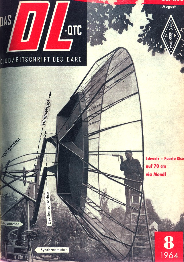
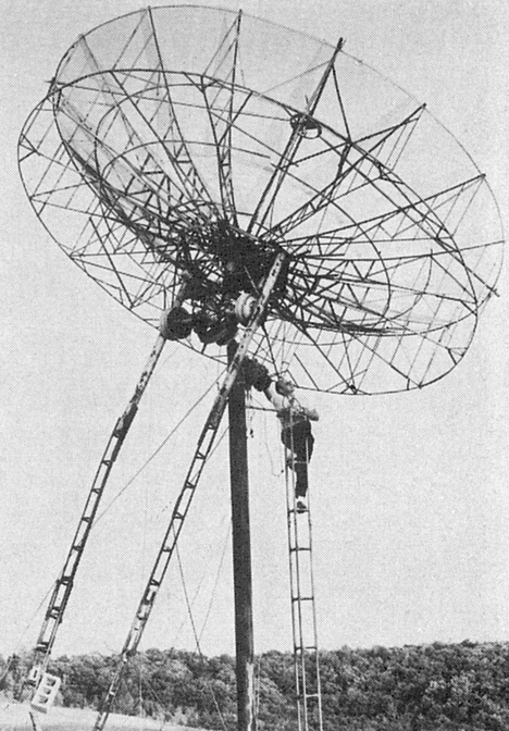
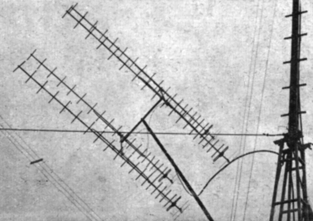
The aforementioned reasons were all important but the last was really the deciding reason. Three years of hearing an occasional echo of our own without one single schedule with another group convinced us that the biggest problem to solve was the guy on the other end. Having made the decision to go ahead, we then divided up the jobs among the various club members and sent out the word to all and sundry that all help would be gratefully accepted. Big Problem No. 1 What do we use for an antenna? Our propagation expert, Gordon Pettingill (W1OTJN) gave us the minimum gain we could use to get practical results. A thumping 35 dB! Furthermore, the experts insisted on a polar mount for the then non-existent antenna. By a stroke of good fortune and the sterling efforts of our official procurer, Dana Atchley (W1HKK), we obtained the loan of an eighteen foot parabolic reflector from the D. S. Kennedy Co. Not only could we borrow it, but it could be easily dismantled for transportation. The transportation division, Fred Collins (W1FRR), Frank Vernon (W1EHF), and Henry Cross (W1OOP), lost no time scaring up a truck complete with several helpers and getting the dish transported from the seacoast at Hingham, Massachusetts, to the mud flats at the RSVHFS. After an evening spent assembling the dish, I was appalled to discover that I had at last acquired an antenna too heavy for me to lift. Not only was it too heavy to lift, but not a thing on the place was capable of holding it up and pointing it at the moon with anything like the degree of accuracy required. And so the leaves turned color and fell, and the cold winds came. Fall turned into winter and our aluminum white elephant lay on its back with its arms stretched toward the sky, daring us to prove ourselves worthy of its help. Amateur astronomer Larry Peavy (mechanical designer), and mechanical engineer Frank Le Baron, (W1TQZ), fought the battle of the drawing board. The rest of us argued the merits of el-az versus equatorial mount. Everyone had his own theory and nobody had a solution which anyone else would agree was satisfactory. Imagine our surprise when our resourceful chief mechanical designer Frank Le Baron requested help in assembling and transporting the new polar mount which he had secretly designed and built. Before first snow fell, the monster was mounted and ready to use. Mechanically, the problems were solved. Electrically, we were caught flat-footed.
Big Problem No. 2 How do you point the antenna at the moon and how do you know where it is? The only an swer is with selsyns and motors. The rest of the winter was spent solving this single problem. Differential amplifiers, two-speed selsyn system, servo motors and hours and hours of calibration finally resulted in a system which allowed us to point the dish at the moon with an accuracy of better than one degree. An automatic moontrack device then keeps the dish moving at the same rate as the moon. An optical spotting scope is mounted on the dish for calibration purposes. It has never been used to aim the dish for moon bounce purposes for the single reason that the moon is always behind a cloud! Big Problem No. 3 Let’s get it on the air! By the middle of May the only remaining problem was to get the project on the air. All the parts were available but getting them hooked up working was a time-consuming job. Help was scarce and many an unsuspecting visitor found himself stringing control wires or running power lines. The Sudbury Radio Club sent a delegation to borrow our generator for Field Day and ended up carrying power supplies and klystrons up to the antenna site. (They never did borrow the generator!) Ted Lanman and Wayne Taft (W1WID) of Tapetone Company stopped in to pass the time of day and ended up spending six hours running power lines from the house to the transmitter site. The word was out! If you don’t want to work, don’t come over! And then it was done! The antenna pointed, the transmitter put out r.f., the receiver listened, and if the moon was above the horizon, we could hear our own echo. Not sometimes, not maybe, but all the time. Big Problem No. 4 Where’s those guys in California? The answer to that question was a month in coming. But when it came, it was in the form of a signal on 1295.976 Mc via the moon. A five-hour battle seemed to prove that signals could be transmitted and received both ways but not quite well enough to make a contact. The goal had been achieved however. Signals had been sent from California to Massachusetts via the moon on 1296 mc. Four days later signal reports were exchanged both ways. A month from now we expect readable phone signals (s.s.b.). Meanwhile, we are open for schedules anywhere in the world. Members of the Rhododendron Swamp V.h.f. Society and others who played a major part in the W1BU effort include Hank Cross, W1OOP; Gordon Pettingill, W1OUN; Paul Day, W1PYM; Fred Collins, W1FRR; Frank Le Baron, W1TQZ; Dana Atchley, W1HKK; Wayne Taft, W1WID; Bob Rafuse, W1RUD; Southard Lippincot, W1DDN; Pat Harris, W1HIV; my wife Helen, W1HOY; and Larry Peavy.
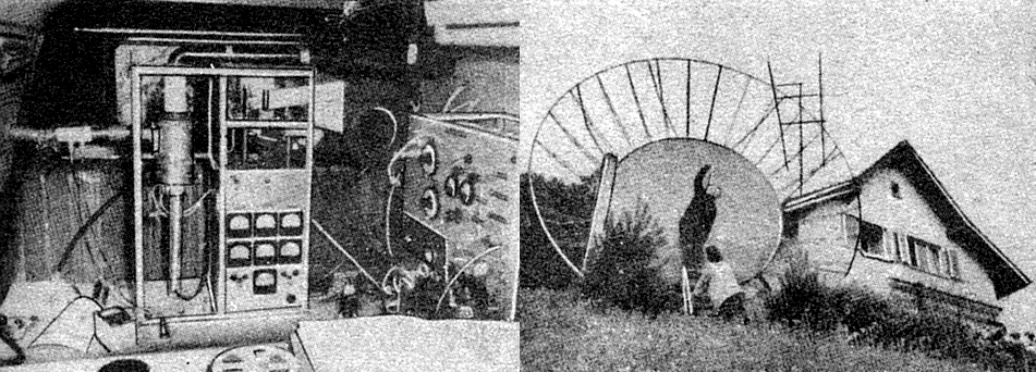
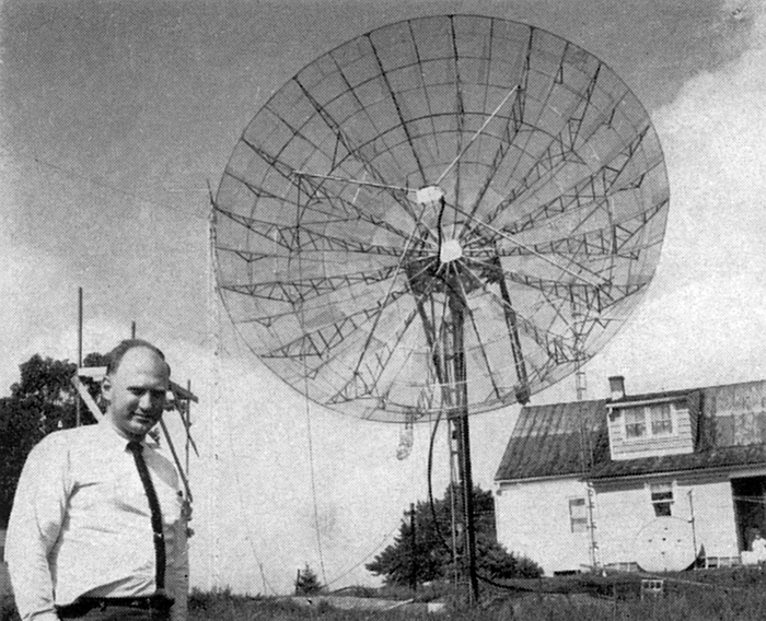
Worldwide DX by moon reflection has been a dream of v.h.f. enthusiasts for years. That it was at least a possibility was demonstrated soon after World War II, when the Signal Corps bounced signals from the moon with modified radar equipment.1 Prospects were none too encouraging, however. The experiment used power far above the amateur limit, a tremendous bill board array, and a complex receiver with a bandwidth measured in cycles. Even with all this, signals were weak and wavery. Still, it was enough to fire the imagination of good hams, and soon a number were hard at work on 144 Mc equipment that might have a chance in the lunar DX race. Just 10 years ago, W3GKP and W4AO recorded one faint beep that sounded authentic, but worked another 2 1/2 years before they got returns strong enough to be sure that they were moon-reflected echoes of the W4AO 2 meter signal.2 Since that time untold ham-hours have been invested in the construction of huge arrays in tended for 144 Mc moon-bounce work. W2NLY, W1FZJ and W6QKI heard their own echoes, after a fashion, but it was all too clear that real communication via the moon on 144 Mc was well-nigh impossible within the framework of amateur regulations. Broadness of pattern with even the largest practical array was the limiting factor at 144 Mc, so in recent years the push has been higher in frequency. 432 would look good but for the 50 watt power limit, so 1296 Mc was the objective. The development of parametric amplifiers, delivering receiver noise figures close to 1 dB, made this look like the moon-bounce band, if there were to be one. Last month, W1FZJ announced through his CQ column that his setup was at last producing consistent moon echoes. It had been in the works for months, and if you’ve heard little of W1FZJ elsewhere in ham radio, you can see the reason now in his backyard - perhaps the most amazing combination of mechanics and electronics ever assembled in one ham station.
The challenge hurled by
W1FZJ in the name of the Rhododendron Swamp V.h.f. Society of Med field,
Mass., W1BU, was not long in being picked up by the Eimac Radio Club, of
San Carlos, Cal. The rest of the story is told elsewhere in this issue.
That the equipment involved is quite some stages up from a 1296 Mc.
Communicator detracts not one bit from the glory won by W1BU and W6HB for
their historic achievement. The first amateur QSO via the moon rates as
one of the top stories ever told in these pages. QST September 1960 The World Above 50Mc - CONDUCTED BY SAM HARRIS, W1FZJ
PRACTICALLY all of my twenty some odd years of amateur activity have been spent on the v.h.f. bands. During that time, all of my v.h.f. activity, and all of yours too, has been ably re ported for posterity in this column by Ed Tilton, W1HDQ. I have learned over the years to rely heavily on Ed’s mature interpretation of the various problems which arise in the v.h.f. field. My efforts in this column will be directed toward maintaining the same high standards. I’m certain I’ll have Ed Tilton’s cooperation in my efforts. If I am to be successful, I will need yours. Please don’t hesitate! Speaking of hesitating, I hesitate to bring up such a controversial subject as tuning above 145 Mc. Nevertheless, the complaints received would indicate that many Technicians feel they are being neglected because the DX workers on the low end of the band are not tuning above 145. Surely, it must be recognized that the modern amateur-band-type communication receiver makes it impossible to tune more than 3 Mc or so at a time. Nevertheless, a dyed-in-the-wool DX worker will look for DX wherever it may he found. If there is DX to be worked above 145 Mc, the DX man will tune above 145 Mc. He certainly is not going to the trouble of moving his receiving equipment up to 145 Mc in order to talk to a Gonset across town. You must remember that this is not a controversy about where he is going to tune, but rather a controversy about what he wants to hear when he tunes. It is per haps unfortunate that some of the most consistent stations operating in the lower portion of the two meter band are operated by people who have worked twenty to thirty or more states and whose prime ambition in life is to work all 50. The like lihood of them finding a new state above 145 Mc is at present very small. It should probably be pointed out that the same stations do not answer calls from people on 144.3 Mc. either. They certainly have nothing against you as a Technician, but only against you as a state they have already worked. This condition is certainly not confined to two meters. It exists on any band where a DX precedent has been established. For instance, a W1 in Vermont is worth 50 W1’s in Massachusetts. In any event, complaining never solves any problems. If you feel there is anything to be gained by having the stations on the low end of the band tune above 145 Mc, you must make your portion of the band more attractive to him than his portion. Don’t make it too attractive, however, or he may move up there transmitter and all. Project Moon Bounce, Echo 1.
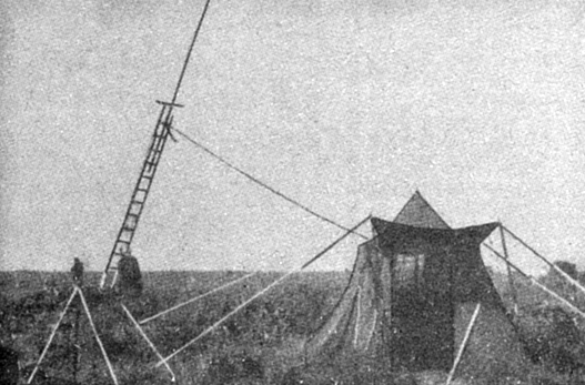
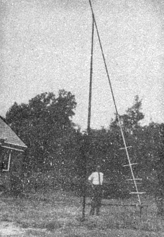
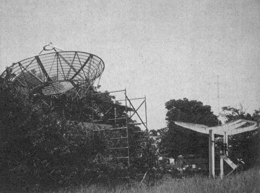
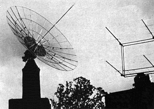
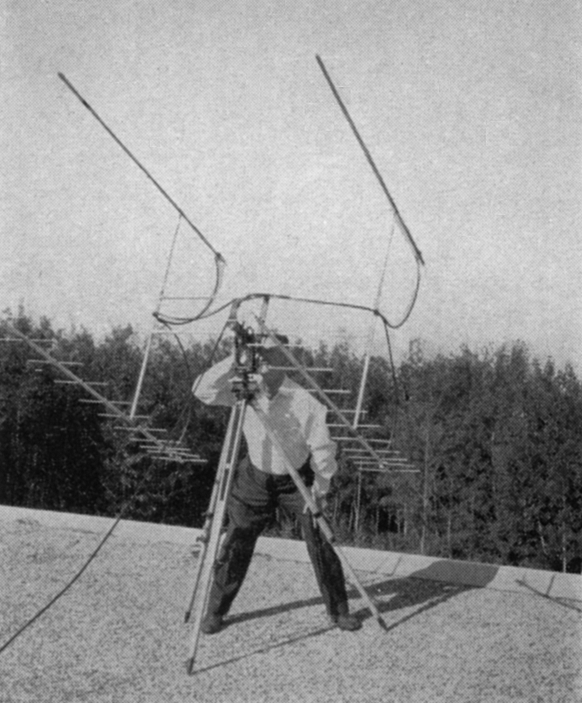
We have received numerous reports on the reception of signals purported to have been reflected from Echo 1. Unfortunately, Echo 1 was launched during the peak of the Perseids Meteor Shower and the majority of the reports received are directly attributable to meteor reflection. The likelihood of stray reception of amateur signals reflected from Echo 1 is very small. In fact, the path-loss for Echo 1 is approximately 5 dB greater than the path-loss for a moon- bounce transmission. For amateur type communication, reflection from Echo 1 offers no advantages over the moon and has several disadvantages. The prime one of these is the rapidity of transit, which introduces considerable doppler shift as well as very difficult aiming problems. It is certainly safe to say that if you cannot receive moon-reflections, you will not be able to receive Echo 1 reflections. Project Moon Bounce on 1296 Mc. at the R.S.V.H.F. Society has just been converted over to single sideband. I was privileged, after considerable effort, to finally hear a weak and wavery signal saying “Hello down there.” Schedules are being maintained with W8LIO of Dorset, Ohio, and W6HB in San Carlos, California. Other schedules are invited. Speaking of W8LIO, Jack of Dorset, Ohio, has constructed since the first of July a complete 1296 moon-bounce receiving station. A 20-foot homemade parabolic reflector mounted on an equatorial mount (see photo) represents an all out effort on the part of Jack and anyone else he could scare up. The dish is built to a 1/4 inch tolerance and exhibits a gain and beam width consistent with a dish of this size. The receiving setup consists of a homemade version of the Microwave Associates paramp used at W1BTJ. Reception of W1BU at Dorset, Ohio, is adequate to allow rebroadcasting on 40 meters so that we can hear our own signals coming back. To date no voice transmissions have been accomplished. The exciter for the transmitter at W8LIO is under construction and will probably be on the air by the time you read this. Plans are to use an RCA 7650 in the final running about 300 watts output. While Jack is no newcomer to the v.h.f. region, this is the first v.h.f. project on which he really bore down. It is obvious that prospective moon bouncers should look to Jack for ad vice on how to do it yourself. QST October 1960
QST November 1960 The World Above 50Mc - CONDUCTED BY SAM HARRIS, W1FZJ JUDGING from the information received, it would appear that there is a belief extant that the use of parametric amplifier techniques in the reception of v.h.f. signals is confined to such esoteric projects as moon-bouncing or satellite tracking. Nothing could be further from the truth. If one examines the history of the development of radio receiving techniques, he will find very few major steps forward in the art. Probably the first giant step was the development of the vacuum tube. The next important development was the superheterodyne receiver. Since this latter development, there have been no major steps in receiving techniques. Of course, there have been many minor triumphs such as the development of the close-spaced planar triodes, but until the invention of the maser a few years ago, no new method of amplifying radio signals was discovered. If we were still working only with maser techniques, one could understand why the v.h.f. fraternity was making slow progress in adapting to the new techniques. However, immediately following the development of the maser came the development of the parametric amplifier. Para metric amplifier techniques are not outside the realm of the average amateur. In fact, the use of parametric techniques requires no more expense and no more additional equipment than is normally found in an average v.h.f. installation. It would appear the only deterrent to general acceptance of parametric amplifiers is the some what sketchy dissemination of information concerning the art.
Furthermore, the erroneous belief that there is little to be gained by improving your noise figure on v.h.f. bands has dampened the enthusiasm of many potential users. The truth of the matter is that I have yet to see a converter on two meters which could not be audibly improved by the use of a parametric amplifier in front of it. Even on the six-meter band where antenna temperatures run considerably higher, there is almost always (This improvement may be masked, however, if you are not in a low-noise location. - Ed.) a marked improvement in signal- to-noise ratio, and invariably a marked decrease in cross modulation problems when a parametric amplifier is used. On the frequencies above two meters, the improvement in signal-to-noise ratio is literally like night and day. On 420 Mc, signals which are absolutely undetectable in the noise of an average converter are perfectly readable when the paramp is installed. Now, if you are really convinced that parametric amplifier techniques are beyond your capability, let us consider the actual facts in the ease. First consider the fact that the first parametric amplifier used to receive “on the air” signals was built by a ham. Second, consider the fact that the ham who did this had never before worked with parametric amplifiers. Third, consider the fact that this paramp was built at home without the use of any exceptional equipment. Fourth, consider the fact that this first crude attempt at making a parametric amplifier gave astonishing results first on six meters, next on two meters, and then on 420 Mc. Furthermore, consider the fact that, crude though this amplifier was, no one has since developed a system capable of giving a lower noise figure. Now, while it is true that you can purchase parametric amplifiers commercially for the approximate price of a new Cadillac convertible, it is also true than an amateur can build a parametric amplifier at home for no more than it would cost to build a 417A-type converter. There is one thing you can be sure of, if you don’t have a parametric amplifier in your v.h.f. layout, you are about as well equipped as a Model T Ford in a modern drag race. If you have read this far, you are probably sitting there asking yourself, “What does he expect me to do now?” The answer is, I expect you to get to work, and prove that you do have the initiative, the ambition, or just plain gumption, to be listed as a member of the v.h.f. fraternity. Look around at your receiving setup. How much feedline loss do you have? If it’s more than 1/2 a dB, fix it. Do you have a tunable coaxial filter in front of your converter? If you don’t, why not? The use of a coaxial filter in front of your converter almost invariably provides an improvement in received signal-to-noise ratio. In addition, it filters out the commercial garbage generally experienced in the urban areas. And it provides the first step towards constructing your parametric amplifier. I don’t suggest that you go out and buy a coaxial filter, but rather that you get busy and build one. The best test for a properly operating filter is to install it in front of your converter while listening to a weak signal. If the signal remains the same or improves slightly, your filter is doing its job. If the signal decreases in strength, one of two things is happening: (a) your filter is not working properly or (b) your converter is matched to the feed line better than any converter I have ever seen. In any event, with a perfectly-matched converter the coaxial filter loss should not exceed 0.2 dB. If you got this far and you still don’t know how to build a parametric amplifier, and if you don’t want to wait for a 1296 Mc paramp being described in QST next month, I suggest you drop me a line stating your problem. When it comes to parametric amplifiers I am as full of helpful hints as Lew McCoy talking to a Novice.
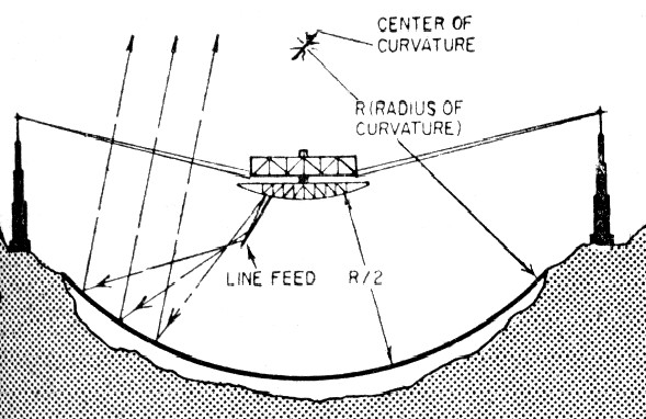
Project Moon Bounce Schedules with W8LIO on 1296 Mc moon bounce during the past month have resulted in sufficient equipment improvement to allow re liable one-way c.w. transmissions. Jack is presently modifying his receiving setup in order to mount the parametric amplifier and converter at the focus of the dish. It is hoped that the improvement of 3 or 4 dB (due to decrease in feed- line loss) will allow our first successful voice transmissions. The status of the various moon bounce efforts known to be in process are as follows. W8LIO, 20-foot parabolic dish mounted on a polar mount. Receiving equipment consists of parametric amplifier into home-built i.f. system. Transmitter under construction. W1BU, 18 foot parabolic dish on polar mount. Transmitter, 300 watts into antenna, sideband or c.w. Receiver is a parametric amplifier into home - built i.f. system. W9QXP, 16-foot diameter parabolic dish on polar mount. Receiver under construction, transmitter under construction. W7GRA, 30 foot parabolic dish under construction. Status of receiver and transmitter unknown. W2CXY, 16 foot dish not mounted as of last information. Transmitter, 300 watts output from c.w. klystron completed. Receiver is under construction. VK3ZDG, 30 foot parabolic dish under construction, parametric amplifier under construction; proposed transmitter to run 30 watts. DJ3FM, 10 foot parabolic dish on order, to be mounted on a polar mount. Receiver, to include parametric amplifier, is being designed. Transmitter proposes the use of the RCA 7650. These foregoing stations do not represent the total number of stations interested in moon bounce work, but rather represent those who have sent a status report on their projects in the last month. I am sure that if you have any words of encouragement for these hardy souls, they will certainly appreciate hearing from you. QST December 1960 A Home-Built Parabolic-Type Reflector for 1296 Mc (Moon-Bounce Capability for $99.98 or Less) by W1TQZ - more here. QST April 1961 The Appearance of the Moon at Radio Frequencies Why Lunar Echoes Sound the Way They Do BY ROLF B. DYCE, K6DSJ, ex-W2TTU The moon, illuminated in visible light, appears as a round disk about 0.5 degree in diameter.1 To the naked eye, the moon looks rough, as if someone had given it a treatment with coarse sandpaper. We also see conspicuous gray areas which have been dubbed “seas,” but which, as far as we earthlings can tell, might really consist of boulder-strewn fields. A look through a telescope, however, reveals the mountainous nature of the moon (some of its peaks are higher than Everest), caused presumably by the tremendous impact of ancient meteorites. Streaks radiate for hundreds of miles from some of the larger craters, possibly caused by debris flying outward from the explosion-like impact, unslowed by any atmospheric drag. At radio frequencies, radar probing of the moon has shown that the moon behaves as a partially polished sphere, giving a bright spot in the center. This characteristic was found by transmitting a short, powerful r.f. pulse toward the moon and noting the shape of the returned echo. Since the moon has a radius of about 1000 miles, there is a possible delay of 11.6 milliseconds from the first returned energy to the last. If the moon were a smooth copper sphere, the energy would he reflected only from the front point of its surface oriented at right angles to the observer on the earth. On the other hand, if the moon were uniformly rough (like frosted glass at optical frequencies), the echo would diminish linearly from its strong leading edge to a distance (range) equal to a lunar radius (the first slice has the largest exposed area, etc.). This behavior is diagrammed in Fig. 1. Between these two extremes is sketched the actual behavior of the moon, a strong initial echo followed by a weaker tail.
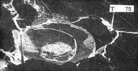
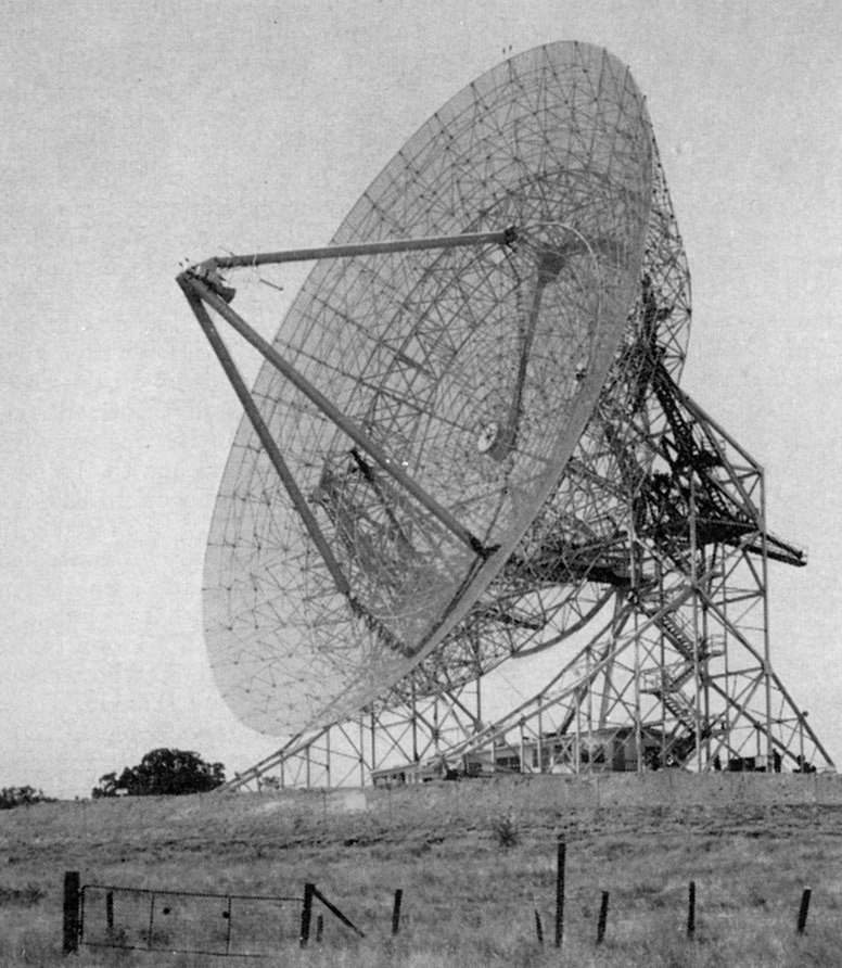
An example of a radar echo is shown in Fig. 2, together with a sketch to scale, of the moon’s curvature. Note the strong echo from the front edge of the moon followed by a gradual decrease of echo strength until the shadow behind the moon is reached. Since the moon has no atmosphere2 or ionosphere3, the radio waves are not bent around the curvature of the moon’s surface. The picture shown in Fig. 2 was made with a 142 foot diameter parabolic dish using 170 kW peak power at 401 Mc and 300 μsec. pulse width.4 The strong leading echo gives more than half of the total echo power obtained with c.w. and is all that is detectable with lower-powered pulse radars.5,6 The strong leading echo must be associated with a “bright spot” near the moon’s center, making the moon appear at r.f. as in Fig. 3.
The echo from the moon has an irregular fade at approximately a few cycles per second at u.h.f., which occurs because the moon very slowly “rocks” or “wobbles” with respect to the observer on the earth, allowing individual echoes from various portions of the moon’s surface to alternately reinforce or cancel each other by phase addition. Experiments show that two stations only a mile apart experience peaks and dips at different times. This slow “libration,” as the astronomers call it, allows us to peek around the edge of the moon. Earth-bound observers have actually seen 59 per cent of the total lunar surface. The apparent libration is chiefly due to three factors: (1) the observer’s motion while attached to a point on the spinning earth, (2) a tilt of the moon’s axis of 6 1/2 degrees that gives about this amount of lunar latitude variation once each month, akin to the earth’s seasons, and (3) an 0.05 eccentricity of the moon’s orbit, despite its uniform slow spin rate, that gives about 8 degrees of lunar longitude variation during the course of an orbit around the earth. The first libration component is largest so that fading is generally most rapid when the moon crosses the observer’s meridian. These components add in complicated ways, sometimes causing the rocking to approach an apparent standstill for a given observer on the earth. On these rare occasions, the fading becomes so slow that only a few cycles per minute are noted. The effect on the radar echoes is demonstrated in Fig. 4. The more distant returns fluctuate more rapidly because they come from portions of the moon having greater line-of-sight velocities. These small velocities are slight compared to the average Doppler shift due to the observer’s motion with respect to the center of the moon. A sophisticated radar is capable of simultaneously measuring distance and frequency shift. A measurement of distance from the earth cuts the moon as shown by the circles in Fig. 5. Lines of constant frequency shift, on the other hand, lie parallel to the instantaneous axis around which the wobble is occurring. Thus, even with a broad beam antenna, the moon can be mapped with only an ambiguity caused by the Southern Hemisphere being folded on top of the Northern Hemisphere. In principle, this could also be applied to echoes from distant planets, regardless of their distance or subtended angle. Preliminary maps of this sort have been made with the Millstone Hill radar, although, to date, no lunar echo has been identified with any particular lunar feature.
Accurate measurements have shown that the moon is about 7 per cent effective as a reflector compared to the theoretical “equivalent target cross section” of π r 2 expected whether the moon reflects as a perfect shiny sphere or perfectly diffuse sphere. The moon has an apparent temperature of about 200 degrees at microwave frequencies, with a delayed variation with solar heating that leads to the conclusion that the moon is covered with a layer of fine dust.7 Radar evidence has been used to guess at the probable rocklike materials making up the lunar surface. So far, these measurements are disputable, although all agree that the moon is not made of green cheese. Transmissions to and from the moon suffer rotation of the plane of polarization so that a vertically polarized transmission could appear as a horizontally polarized echo hack at the receiver, this twist being added during each passage through the F-region of the ionosphere. This is due to the presence of the earth’s magnetic field and is called the Faraday effect.
At 400 Mc, about one rotation each way is experienced at noon for observers at the latitude of the United States. The amount of rotation is inversely proportional to the square of the operating frequency and so amounts to 90 degrees or less at 1296 Mc. The Faraday effect has been used to demonstrate that there are about twice as many electrons above the maximum density level of the ionosphere as below this level. To avoid embarrassing loss of signal, the transmitting station should use circular polarization, and the receiver use the opposite circular polarization. The next best extraterrestrial object for echo purposes is Venus - five minutes round-trip time and roughly a million times more difficult to detect than the moon. However, this has already been done with great difficulty by computer-processing of the receiver noise by American, 8 British, and possibly Russian research groups. The ionized gases surrounding the sun have also given a feeble radar echo at 25 Mc.5 Although the sun has a round-trip time of 15 minutes, it is a larger object and so is only about 100,000 times more difficult to detect than the moon. Present data indicates that Venus may have a bright central echoing region like the moon. There is reason to believe, on the other hand, that the sun may look jagged to radio waves and may be several times its optical size. In conclusion, the optical appearance of the moon, sun, or planets is no clue to their reflecting properties at radio wavelengths. Radio-reflection experiments, therefore, promise to reveal new information about these distant bodies.
References: 2) Dollfus, “Nouvelle Recherches d’une Atmosphere au Voisinage de la Lune,” Compted Rendus 234, pp. 2046-2049, 1952. 3) Elsmore, “Radio Observations of the Lunar Atmosphere,” Paris Symposium on Radio Astronomy, Bracewell, ed. Stanford University Press, 1939. 4 Leadabrand, et al., “Radio Frequency Scattering from the Surface of the Moon,” a letter to the editor of Proc. IRE, IRE, Vol. 48, No. 5, p. 932, May, 1960. 5 Trexler, “Lunar Radio Echoes,” Proc. IRE, Vol. 46, No. 1, pp. 286-292, January, 1958. 6 Yaplee, et al., “Radar Echoes from the Moon at a Wavelength of 10 cm,,” Proc. IRE, Vol. 46, No. 1, pp. 293-297, January, 1958. 7 Gibson, “ Lunar Thermal Radiation at 35 Kmc., Proc. IRE, Vol. 46, No. 1, pp. 280 286, January, 1958. 8 Price, et al. , “ Radar Echoes from Venus,” Science 129, 751., 1959. 9 Eshleman, et al. , “ Radar Echoes from the Sun,’‘ Science 131, 3397, PP. 329 332, Feb. 5, 1960. QST May 1961
The World Above 50Mc - CONDUCTED BY SAM HARRIS, W1FZJ It was just a year ago this month that the Rhododendron Swamp V.H.F. Society first started hearing echoes of their 1296-Mc, signals returning from the moon. These first echoes were obtained using a 30-watt output transmitter and an 18-foot parabolic dish. They were, in truth, weak, but they were repeatable and could be obtained at will. At the time we only knew of three other groups who were seriously interested in moon-bouncing experiments. At the present time there are at least 30 interested groups, and 12 of these groups are actively engaged in constructing equipment for use on moon-bounce experiments. Not all the interest has been centered on 1296 Mc. Several of the groups are concentrating on 2 meters; others are working on 50 Mc. and 432 Mc. A good portion of the “planning but not in construction stage” groups are concentrating on 220 Mc. There is a natural tendency for anyone who is planning a moon-bounce effort to choose the band on which he feels his equipment is best suited to the task. In our efforts we explored the possibilities of 50 Mc. and 144 Mc. and as a result of these explorations decided that the most useful frequencies would be those above 420Mc. The reasons we had for choosing 1296, however, did not exclude the possibility of using the lower frequency bands. The accompanying chart which shows antenna temperature vs. frequency is one of the prime reasons for looking above 432 Mc. to obtain optimum moon-bounce transmissions. As can be seen, the antenna temperatures at 144 Mc. are 10 times higher than those at 1296 Mc. 220-Mc. antenna temperatures are only 5 times as bad and 432 Mc. antenna temperatures are almost comparable. The prime deterrent for 432 Mc. is, of course, the existing power limit which makes the necessary antenna gain prohibitively high. This additional noise obtained at the lower frequencies does not, however, rule out their use for moon-bounce purposes, as the path loss in sending the signal to the moon and back is considerably less at the lower frequencies. Without going into any extended calculations on how we obtain the number, the path loss of a one-meter signal leaving the earth, reflecting from the moon and coming back to the earth is 258 dB. (This figure neglects other incidental changes in the path loss caused by variations of distance to the moon, absorption in the ionosphere, etc.) Now this 258 dB at one meter varies as the square of the wavelength or, to put figures on it at 1296 Mc., the path loss has increased to 271 dB whereas at 144 Mc., it has decreased to 252 dB - so that a signal traveling to the moon and back at two meters suffers 19 dB less loss than one traveling the same route on 1296 Mc.
Interestingly enough the gain of a fixed aperture antenna array varies in the exact opposite manner. For example, an 18-foot dish can give 35 dB gain at 1296 Mc. and 16 dB gain at 144 Mc. It should be observed, however, that the additional 19 dB gain obtained on 1296 Mc. for the same size dish is obtained once on transmitting and once on the receiving so that, in fact, the system antenna gain is 38 dB higher on 1296 for a constant size array. Now in case you’re confused as to what we mean by path loss, the 271 dB path loss for a 1296-Mc. signal means that a signal leaving your antenna will come back from the moon 271 dB weaker than it left. In calculating your chances of successful moon bouncing, the first step is to subtract the antenna gain from the path loss. In the case of an 18-foot dish used on 1296 Mc., this gives us approximately 35 dB, which gain will be obtained once when the signal is transmitted and once more when the signal is received, for a total of 70 dB antenna gain. This 70 dB subtracted from the path loss leaves a resultant path loss for our signal of 201 dB. The next calculation required to evaluate your system is to determine the weakest signal that your receiver can detect. In order to properly evaluate the minimum discernable signal capabilities of your receiver, the band width of the receiver, the noise figure or temperature of the receiver, the loss in the feed line between the antenna and the receiver, and the temperature of the antenna or the incidental noise coming in the antenna must all be taken into account. By modern standards, there is no excuse for having a receiver noise figure any worse than 1 dB and on 1296 a system temperature of 150° Kelvin should be obtainable. This would be approximately equal to having a 2 dB noise figure system. The additional noise over the receiver noise figure is generally incurred in feed-line loss and added antenna temperatures. This is the point in which the 50- Mc. or 144-Mc. receiving systems will suffer most, as the added antenna temperature will degrade the performance of the receiving system. The band width of the receiver can be chosen to suit the particular fancy of the operator. In general it is safe to say that a 100-cycle band width has a 10 dB signal-to-noise advantage over a 1000-cycle bandwidth. If we assumed a 2 dB noise figure and a 100-cycle passband, the equivalent noise input of this receiver would be -151dBm or 151 dB below 1 milliwatt. Now this 151 dBm. is subject to considerable variation due to the integration ability of the human ear. Or to put it another way, the 10 dB advantage of the 100-cycle bandwidth over a 1-kilocycle bandwidth may be entirely offset by the ability of the ear mechanisms to produce an equivalent narrow band width of their own. Unfortunately this innate ability of the ear is somewhat difficult to calculate and varies to some degree from operator to operator, as witness the DX man who can hear more with an SW3 than another one can hear with a 75A-4. Suffice it to say that the 151 dBm signal which will appear in the 100-cycle bandwidth is a signal equal to the noise already existing in the receiver and to the ear will be approximately 10 dB above the noise. It now remains only to calculate how much transmitter power is required to come back from the moon with a signal of at least -151 dBm. The difference between 1 milliwatt and 1 watt is 30dB. If our receiver can hear a -151 dB below a milliwatt signal, it can obviously hear a -181 dB below a one watt signal. Now the remaining path loss after subtracting the 70 dB of antenna gain was found to be 201 dB of loss. Thus if we transmitted a 1-watt signal the returning signal would be 201 dB below 1 watt or approximately 20 dB weaker than our receiver capability. So in order to obtain a signal equal to our receiver capabilities, we must add 20 dB of power to our 1-watt transmitter or 100 watts. So we find that a 100-watt transmitter using a 35 dB gain antenna at a frequency of 1296 Mc. into a receiver having a 2 dB effective noise figure and a 100-cycle passband will return a signal which is equal to a noise in our receiving system and which to our ears will be somewhere between 6 and 12 dB over the noise. So much for system requirements on 1296 Mc. The only case that can be made for lower frequencies is that the path loss is less and the antenna temperature is somewhat higher and these to some extent balance out.
The second problem which occurs at lower frequencies is the phenomena known as faraday rotation. Without delving into the technical aspects, what this means in plain English is that the polarization of a signal which passes through the ionosphere is shifted. The amount that the polarization is shifted depends on the angle at which it passes through the ionosphere and the frequency of the transmitted signal. This faraday rotation is practically zero at 1296 Mc. However, at 432 and lower it is a definite problem which must be contended with. Now one should not assume that the rotation is completely random and, in fact, as one tracks the moon the resultant change in polarization on the returning signal varies quite slowly. So if the receiving antenna can be rotated in polarization to optimize the received signal, it will be quite adequate for at least an hour’s transmissions. The thing that is difficult is to predict exactly how much it will be at a given time for any given frequency. The obvious solution to this problem is to use circular polarization. However, while this solves the problem of faraday rotation, it does not solve the problem of hearing your own signals as the direction of rotation of the circular polarized signal is reversed when it is reflected from the moon. This means that if you transmit left-hand circular polarization, the received signal will come back with right-hand circular polarization. Once again this would not be a problem if the receiving equipment is separate from the transmitting equipment, as the transmitter can use left hand circular and the receiver can use right hand circular. However, the operator who is attempting to hear his own signals must provide a system of reversing his direction of rotation between transmitting and receiving. Furthermore, it means that if two stations are set up to exchange signals, all other stations can either hear one of the other but not both of the stations. The solution is an antenna with a switchable circular polarization and almost all commercial type installations have this capability. All this really boils down to is that a 150-foot parabolic dish with provision for right and left hand circular polarization will give approximately the same results on 144 Mc as an 18-foot dish will give on 1296 Mc. Furthermore, the signals from the Rhododendron Swamp VHF. Society moon-bounce effort could be received on a 4-foot diameter parabolic antenna system with a good parametric amplifier following it.
Speaking of moon bounce, as we were, we
were just privileged to receive a visit from Dr. Karl G. Lickfield, V.H.F.
Editor of the Deutscher Amateur Radio Club in Germany. Karl is engaged in
a scholarship effort to produce a 1296-Mc, moon-bounce installation. With
any luck his installation should be completed and on the air before the
end of 1961. He plans to use a 10-foot parabolic dish on a polar mount.
His receiver, of course, will utilize a parametric amplifier feeding a
narrow-band i.f. system. The transmitter will employ an RCA 7650. To date
he has the antenna and is expecting within a month completion of his polar
mount. The transmitter hardware for the final stage is completed. And,
hopefully, after his return visit to various installations in this
country, his parametric amplifier will be completed. PROJECT MOON BOUNCE The 1296 moon-bounce effort at the W1BU location is back in operation. Schedules are being kept with W9QXP and company and with the club station at Purdue (W9YB), Indiana. So far no schedules with any West Coast or out of the country stations. W8LIO at Dorset, Ohio, is in the process of adding to his dish to bring it up to thirty feet in diameter. This should result in the first amateur phone contact via the moon bounce route. W1BU will be open for schedules during the months of July, August and September. QST July 1961
Moon Bounce K1HMU at Farmington, Connecticut, has his 144 Mc moon-bounce set-up completed and is in operation on a more or less regular schedule. Operation is on 144.252 (give or take 3) kc. The antenna has 178 elements in clock wise circular polarization. Naturally, reception should be attempted using counter-clockwise circular polarization. Actually, as long as Ned has done all the work on his end to provide a solution to the faraday rotation problem, his signals can be heard on either of the popular linear polarizations as well. (Assuming sufficient gain, etc.) Transmitter is running 1 kW input, and receiver has adequate selectivity and a good paramp in front. Unfortunately, by the tune you read this his advance schedule will have been completed. If you weren’t on his advance mailing list and are interested, I would suggest writing him for further information. W6MMU informs us that “The Two Meter and Down Club” have completed their 1296 Mc moon-bounce receiving set-up and are in a position to start listening as of the 25th of August. Their set-up includes a paramp by Don and is using an eight foot parabolic reflector on an equatorial mount. Details are hard to come by but will probably filter out of the boondocks as soon as they have had some success.
Meanwhile, at the other end of California. we have WA6JZN and W6AXN who have completed 10 and 16-foot polar-mounted dishes and are ready to listen. Gene, WA6JZN, has a W6MMU paramp feeding a W1OOP converter. I.f. is 16 mc to 455 kc with crystal-lattice filter giving 400-cycle selectivity. An audio filter of the bridge type allows variable selectivity down to 8 c.p.s. Receiver lo string starts at 5 Mc. Ten-foot parabola is built using a system worked out by W6AXN. 5 has his 16 footer (made by the same process) ready to go and will be transmitting by the time you read this. In Ohio W8LIO has completed the enlarging of his dish and now has a 26 footer in operation. Preliminary tests have been very gratifying and it is very likely that the first s.s.b. voice transmission will be accomplished in the next month. Jack has one of the UPX-4 transmitters and will soon have 300 watts of c.w. feeding his antenna. The UPX-4 uses 6x 2C39A’s in a ring amplifier and looks like the answer to a moon-bouncer’s dream, as far as the transmitter is concerned. One European effort on 1296 is nearing completion. Karl, DL3FM, says that the only remaining big effort is to get his ten-foot dish mounted on its roof-top polar mount. Karl plans to enlist the aid of a helicopter in moving the dish to its final resting place. HB9RG has been listening daily on schedule for W1BU. Transmission schedule at W1BU is too variable to supply a list. We operate on a twenty-minute notice and only as requested to do so. So far there are five active listening installations in the U. S. Only one active transmitter, however. QST October 1961 Space Communication and the Amateur Noise Sources and the All-Important Signal-to-Noise Ratio BY RAPHAEL SOIFER, K2QEW What are the technical factors that must be weighed in assessing the practicality of ground-to-ground amateur communication via space vehicles? In this article the author shows that the problem is one of establishing a usable signal-to-noise ratio, and discusses the various components that contribute to the noise background. Signal propagation and the important influence of equipment, including the communications satellite itself, will be covered subsequently.
AMATEUR radio stands today just over the threshold of a new era. The year 1960 saw the first concrete steps taken in the effort to provide the amateur with a place in the rapidly unfolding world of space communications. Thus our position today is akin to that of 1922, when QST trotted out its famous exclamation points to announce that the Second Transatlantics had succeeded - that, for the first time in amateur history, American amateur signals were heard across the Atlantic. This discovery that wave lengths below 200 meters could actually be used for long-distance work led, in the following year, to the first transatlantic two-way. Where the story led from there does not require my further elaboration. (Except possibly to point out that one of the operators at the M. I. T. ham station, 1XM, during the Second Transatlantics was a young electrical-engineering student named J. A. Stratton who, 38 years after 1XM’s success in the tests, was formally inaugurated as president of this same Massachusetts Institute of Technology.) It will be the purpose of this series of articles to discuss realistically the problems which space communication poses for the amateur fraternity, and to suggest some possible directions of attack on the solutions to these problems. It will become apparent - if it is not already - that we are dealing largely with questions, unknowns, and challenges where we have been accustomed to laws, figures, and circuits. Supplying answers to these challenges, I hasten to add, has been the amateur’s role throughout his history. I am confident that, just as his father conquered the mysteries of short-wave radio forty years before, the radio amateur of the 1960s and 70s will conquer space. The Problem The entire problem of space communication can be expressed in four words: signal-to-noise ratio. This s.n.r., as it is called, is usually expressed in decibels. We will define it as the ratio, measured at the receiver, between the received power of the desired signal and the total measured noise power, both received noise and that generated in the receiver itself. The s.n.r. is the key to the entire problem. All the other so-called “obstacles” to practical space communication - tracking, antenna size, transmitter power, low-noise receivers, satellite size, and the rest - are merely manifestations of the basic question of obtaining a sufficient s.n.r. This ratio does not care how it is obtained. If technical or legal considerations limit the signal power, a suitable reduction in noise will suffice to produce the required s.n.r., and the system will work just as effectively. More generally, a deficiency in one part of the system can be made up in another part without affecting the s.n.r. and, through it, the performance of the system. It cannot be over-emphasized that only the signal to-noise ratio is important - not signal power or noise by themselves. The sn.r. controls not only whether or not a system will work, but also how well, how efficiently, and how reliably. If the s.n.r. is more than a few db. below unity, no operator in existence will be able to copy the transmitted signals (By means of specially designed pulse trains, transmitted information has been detected with the s.n.r. as low as -30 dB. We will return to this topic later in the discussion.). The communications system will, in short, be a failure. Values from essentially unity up to 6 db. or so may be termed marginal. In the range around unity, a highly skilled operator may be able to copy short snatches of c.w. As the s.n.r. goes up, copy becomes less and less difficult, becoming fairly normal at 10 dB or thereabouts. Voice work requires a higher s.n.r. Values from 6 to 10 dB may here be termed marginal, the same conditions applying as for c.w. - except, of course, for the higher s.n.r. requirement. Copy becomes normal on voice at values greater than 10 or 12 dB. The higher the s.n.r., in general, the more sophisticated the method of communication that may be used. For s.n.r. values greater than 17 or 20 dB, slow-scan television becomes practical. At higher values, multiplex techniques be come feasible, as well as improved performance when using the modes discussed heretofore.
Unfortunately, values of received signal and noise generally do not remain constant with time. Because of their variation from season to season, day to day, and minute to minute, systems must generally be designed to have a higher s.n.r. than would ordinarily be needed. This provides margin in case of bad conditions - in a word, reliability. The greater the percentage of reliability desired, the greater margin must be provided in the form of increased s.n.r. in the system design. In considering the various elements which contribute to this all-important ratio, we will consider first the noise components - bearing in mind, of course, that noise does not tell the whole story, that only when combined with signal strength in the form of the s.n.r. is it actually significant. Sources of Noise The noise heard at the output of the receiver is made up of several components, chiefly cosmic noise, tropospheric noise, apparatus noise, and man-made noise. Beneficially, the stronger component will tend to screen the weaker one from being noticed, a condition which stems from the fact that most noise is made up of nonperiodic waveforms. Thus, one often can concern himself only with the strongest noise component in a given situation and neglect the others. This nonperiodic property also means, unfortunately, that noise cannot be phased out, as can sinusoidal waveforms. We will consider each noise component in the order given above. Cosmic Noise. This is noise that reaches our planet from other regions of the universe. It is generated, among other sources, in interstellar gas clouds. Cosmic noise is of principal concern between 20 Mc and 1000 Mc, and decreases logarithmically with increasing frequency. Being a close approximation to “white” noise - i.e., noise made up of random pulses distributed throughout the frequency spectrum - there is little that can be done to counteract it (For supplementary information on cosmic noise, see McLaughlin and Hobbs, “Noise Factors Affecting V.H.F. Communication,” QST, June, 1961; and Bray and Kirchner, “Antenna Patterns from the Sun,” QST, July, 1960.). It does, however, have one interesting property: It is not received with equal strength from all directions. It can be reduced, then, by aiming antennas in minimum-noise directions. Other considerations obviously make this method one of limited usefulness. Interestingly enough, it was precisely this directional property that led early investigators, Karl Jansky and Grote Reber, to discover the true origin of this noise form, leading eventually to the identification of the most powerful radio stars. Thus was founded the important science of radio astronomy (For background information on radio astronomy, see Goodman, “Radio Astronomy,” QST, May, 1956). Tropospheric Noise. This is the familiar “static” heard on lower frequencies near thunder storms. As its name implies, it is generated by weather phenomena in the lower atmosphere and is by far the most significant natural noise source on frequencies below 20 Mc. It drops off sharply with frequency, and above 30 Mc it may be ignored. Except for clipping to eliminate the sharper peaks, little can be done to alleviate it in the frequency range in which it is found.
Apparatus noise becomes important at frequencies above 30 Mc, and its stature as a problem increases approximately logarithmically with frequency. It can be greatly minimized by using specially designed antennas with a low equivalent noise temperature, and by using low noise amplification devices in the front end of the receiver. The question of r.f. amplifier noise figure is well known to most amateurs and need not be gone into here, except to state that this is one area in which a great deal of development work has been done and is still going on. At frequencies where apparatus noise can predominate, the best of the low-noise triodes have today been superseded by such devices as parametric amplifiers. Another branch of development has sought to reduce amplifier noise by reducing the temperature at which the amplification is con ducted (remember the T in kTB!) and in amplifying by means of solid-state devices which offer high transconductance with a minimum of random molecular movement. Such development led to the ruby maser which operates near absolute zero and which contributed largely to the success of Project Echo. The wise amateur will keep a wary eye on these developments, for they represent a great field for improvement of the state of the art. Incidentally, front-end noise has a tendency to mask noise originating in the later stages of the receiver, so it may not be necessary to worry much about noise considerations when designing the i.f. strip. Man-Made Noise. This noise, emanating from electric motors, automobile ignition, switching, and similar products of our own technology, can extend throughout the radio spectrum and is in general a most serious problem wherever it is found. In fact, it will often prove a good deal stronger than all other noise types combined. Because it takes so many different forms, specific rules about it are impossible to formulate. The sharper peaks, such as those typical of ignition noise, may be clipped off or blanked out by limiters or silencers. However, there is little else that can he done at the receiver to eliminate man-made noise, aside from such obvious measures as filtering the power line. The saving factor, however, is that man-made noise is only infrequently found in bands above 500 Mc. It’s just like the plague, though - if it breaks out in your vicinity you’d better move. Man-made noise usually will show directive properties, so the antenna can be aimed so as to minimize it. But, just as in the case of cosmic noise, this technique is of limited value. Nevertheless, use of highly directive antennas can he shown to have a beneficial effect in combating this noise, except perhaps in the larger cities. Bandwidth Since noise values vary a good deal from station to station, it would not be possible to present a quantitative analysis of noise level as a function of frequency which would hold for all cases (Specific values of noise level are too variable to be quoted here They are treated in engineering handbooks such as Reference Data for Radio Engineers, Fourth Edition, published by I. T. & T. Corp., 67 Broad St., New York City). Nevertheless, based upon the noise sources we have considered, we may conclude that less noise will be encountered on u.h.f. and higher frequencies than on lower bands. Thus, with a wary eye cocked on the s.n.r., we will consider these higher frequencies to be more suited to our purposes than those lower in the spectrum. Comparing this conclusion with the roster of amateur bands - and remembering that the 420 Mc power limit robs us of 13 dB in obtainable s.n.r. - we see that the lowest useful amateur assignment in the uhf. range begins at 1215 Mc. Let us then adopt this value as the lower bound on what we will eventually call the optimum range for amateur space communications. We are not yet in a position to evaluate the upper bound, which will come out of the discussion of propagation and path losses in a subsequent article. At this point it is well to recall the factor kTB we came across in discussing apparatus noise. It tells us that the greater the bandwidth, the more apparatus noise. It turns out that cosmic noise and tropospheric noise similarly increase with bandwidth. In the case of man-made noise, the relationship is not so simple because of its widely differing forms. In general, though, man-made noise does increase with bandwidth, but the increase may not be linear. In order to minimize noise and thereby raise the s.n.r., then, one thing we can do is to reduce the bandwidth of the receiver. This can be done easily enough, and is in fact standard procedure. But useful as narrow-band systems undoubtedly are, they are not, at microwave frequencies, an unmixed blessing. For one thing, frequency stability in both the transmitter and receiver can be quite a problem in this part of the spectrum. Narrow bandwidth in the receiver means that care must be taken to insure that the signal will not drift so far that it leaves the passhand. This means ultrastable oscillators and converters, and, as W1FZJ will be very happy to inform you, these can drive an engineer mad! Additionally, systems engineers know that bandwidth serves as a limiting factor on what they term the “data rate,” or the rate at which information can be sent. The faster you wish to send information, the more bandwidth your transmissions must consume (and the system thus must be capable of handling). In c.w., for example, the bandwidth occupied by a signal increases in direct proportion to the sending speed, and in cycles per second is approximately equal to four times the sending speed in words per minute.
The human voice is a
notoriously poor user of spectrum space - most people talk at about 150
w.p.m., yet a single-sideband station uses up about 3000 cycles of space,
and a d.s.b. or am. station about 6000. Conventional f.m. may use as much
as 150 kc, conventional television four to six megacycles (slow-scan can
be transmitted in an ordinary s.s.b. channel). In considering bandwidth, we should not omit mention of pulse modulation methods. These may use many hundreds of kilocycles of bandwidth. In doing so, the pulse system puts out much more peak power in its short pulses than can a com parable ow. system, which under some conditions may compensate in the s.n.r. for the increased bandwidth. This is, in fact, the principle behind the early radar systems of World War II, as well as some present-day radar. Some engineers contend that, through the use of ingenious coding techniques far beyond the scope of this discussion, pulse emission may actually be employed to reduce the s.n.r. requirement for any given degree of reliability to levels well below those we quoted earlier. This is done, basically, by holding down the modulating data rate to what is actually needed - rather than attempting to transmit the original information, which contains many bits of superfluous data. Auxiliary circuitry at the receiver is then employed to translate the coded pulses back into aurally (or visually) useful information. While the pulsing process itself introduces a great deal of superfluous information of its own - thus increasing the bandwidth - the coding process circumvents this difficulty by making it unnecessary for all the transmitted data to get through. Hence the received data rate duty cycle, and with it the s.n.r. requirement, may be made much smaller than would he required were all the transmitted information necessary - smaller, in fact, than if the original information with its smaller transmitted bandwidth and continuous reception requirement were being used. In summary, then, an engineer - or a radio amateur - would like to design his system to handle the maximum possible bandwidth so as to minimize stability problems and increase the data rate reception capability. But such a design, we recall, must of necessity increase the noise. However, if the s.n.r. designed into the system is made high enough to absorb the additional noise and still remain above the requirement for the degree of reliability desired, then the bandwidth increase may be made. Thus we see that the s.n.r. determines the maximum bandwidth which a circuit can handle for any desired degree of reliability. That is, stability requirements and data rate reception capability may be considered simply as manifestations of the s.n.r. Our old friend has returned, and will keep popping up throughout our discussion. QST November 1961 The Mechanisms of Space Communication Propagation, Satellites, Antennas and Associated Equipment BY RAPHAEL SOIFER, K2QBW The preceding article (“Space Communication and the Amateur,” November 1961 QST) showed that communication by means of some medium in outer space is essentially a signal-to-noise ratio problem. Taking it from there, the author surveys the questions of propagation vs. frequency active vs. passive satellites, antennas and tracking, and other factors that bear on getting a reliable signal back from space vehicles. LAST month we discussed the all-important role of the signal to noise ratio in determining system performance parameters - in plain language, whether or not the thing will work. We found that the highest possible s.n.r. is always desirable, since it will make the system more reliable and versatile. From a qualitative study of the various noise forms affecting amateur space communications, we decided that it would be best; to conduct such work on frequencies above 1215 Mc. We turn now to a discussion of the second component of the signal-to-noise ratio, the received signal power. Let us see how, in a space communication system, the transmitted signal comes to arrive at the r.f. amplifier input of the receiver. In our generalized system, the signal generated by the transmitter is attenuated by the transmission line, concentrated (that is, from a system standpoint, amplified) by the transmitting antenna, partially absorbed in the atmosphere, rotated in polarization in the ionosphere, attenuated all along by free-space path loss, relayed by the relay point in space, rotated once more in its return through the ionosphere, absorbed some more in the atmosphere, amplified by the receiving antenna, and attenuated by the receiving transmission line. Sort of makes you happy you aren’t a signal, doesn’t it?
Line Losses First to come to mind are the two line losses. There are various measures we can employ to reduce these. For one thing, we can use properly matched sources and loads to insure that the s.w.r. on the line is essentially unity. For another, we can keep the transmission line as short as possible, because line loss increases with line length. Third, we can use line with the lowest possible loss per unit length. This rules out the popular flexible coaxial cables. For the frequencies with which we are concerning ourselves wave guides are practical, though expensive. The theory behind transmission line loss per unit length is beyond the scope of this discussion - except to make the blanket statement that all means should be explored by the amateur to reduce his line losses. Material on microwave (and u.h.f.) power transmission is plentiful in most libraries, and should be read by anyone planning serious work in space communication. Faraday Rotation Next to come to mind are the two wave rotations. These are perhaps easier to eliminate than to explain. Briefly, it has been found that when an electromagnetic wave passes through a highly ionized medium - such as the ionosphere - in the presence of a magnetic field - such as that of the earth - its polarization rotates. With conventional linearly polarized antennas, this results in a cross-polarization loss similar to that observed when a vertical is used in working a station equipped with a horizontal beam. There turns out to be a rather sneaky way of eliminating “Faraday rotation” loss, as it is known. If one transmits a signal in which the polarization is continuously rotating, and designs a receiving antenna to accept such a rotating wave without loss, then any rotation induced in transit will have no effect whatever. Such a wave is called “circularly-polarized.” One way to generate and receive one is to use the helix type of antenna. This is in fact standard procedure in many industrial space communication and radar tracking projects, and could be adopted by amateurs with little difficulty. An interesting feature of a circularly-polarized wave is that when it is reflected, as from the moon or a satellite, its sense of rotation - that is, whether it is rotating clockwise or counterclock wise —- is inverted. This means that for passive communication systems, the receiving helix must have a left-hand winding if the transmitting helix has a right-hand winding, or vice versa. Screwy, aren’t they? The Atmosphere Atmospheric absorption, which accounts for two more terms in the total path loss, affects mainly the higher end of the radio spectrum. Such losses as affect the amateur service occur in the ionosphere from auroral absorption, and in the troposphere from water-vapor and oxygen line absorption. The same auroral ionization clouds which greet v.h.f. men with thoughts of DX bring no cheer to us, for we are trying to get signals through them, while they persist in absorbing and reflecting. Although their effect is serious at v.h.f. and lower uhf., by 1215 Mc the clouds are relatively transparent and cause little difficulty. Tropospheric absorption, on the other hand, increases sharply beyond 10 Gc (1 Gc = 1000 Mc), and is a serious problem in this frequency range. For example, our amateur band 21-22 Gc comes right at the peak of the water-vapor absorption curve, making it one of limited useful ness for space work when compared with the next lower decade of frequency. Absorption continues at a high level throughout the “above 30 Gc” range. This absorption effect causes us to place an upper limit on our optimum range of frequencies suitable for amateur space communications at 10.5 Gc, just before the sharp rise in water-vapor attenuation. The five amateur bands in our optimum range of 1215 to 10.5 Gc contain a total spectrum of some 1210 megacycles, which should be adequate for years to come. Incidentally, the reader is warned that there is a tendency among engineers to refer to trans mission line and atmospheric signal losses as a form of noise. The reasoning behind this is simple: Inasmuch as the s.n.r. alone determines performance parameters, we can treat a given amount of signal attenuation and consequent s.n.r. reduction as if the reduction were caused by the introduction of an equivalent amount of noise. This equivalent noise is expressed as an equivalent noise power, or sometimes as an equivalent noise temperature (remember kTB?) Al though we will continue to treat them as signal attenuations, the reader will undoubtedly see these equivalent noises in his further reading, and as long as he recognizes these shifts in nomenclature for what they are, he should encounter no trouble. Wave Spreading Free-space loss is next on our agenda. This is derived from the law that the power intercepted per unit area from an electromagnetic wave propagating from a point source varies as the inverse square of the distance from the source. In our case, one can show that the received signal power actually varies roughly as the inverse fourth power of the altitude of the relay point (As we will say later, it actually varies inversely as the product of the squares of the satellite range from each station. This may be visualized as follows: Station A transmits a signal, decreasing in power as 1/R2 until it reaches the relay point. But in order for the signal to get to the receiver, it must again decrease as 1/R2 from the relay point hack to the receiver. Mathematical approximation leads to the result that received power varies roughly as the inverse fourth power of the relay point altitude). All right, the man says, keep the relaying point low, and this loss will be minimized. This is fine, except for the following catch: We recall that microwave signals propagate in straight lines therefore, we have to have a line-of-sight path from both stations on the ground to the relay point in space. If the two stations are moved farther and farther apart, the altitude of the re lay point must be increased, because of the curvature of the earth, so it can continue to “see” both stations. This increased altitude, while resulting in increased range, must also result in increased free-space loss. Thus, one can easily show that range, too, is a function of the system s.n.r. The higher the s.n.r. designed into the system to start with, the farther the relay point can be pulled away from the earth before the s.n.r. dips below the required minimum. There is another catch as well: The ground station not only must “see” the relay point, it must “see” it at an elevation angle sufficiently high so that waves can be propagated to it with a minimum of effects caused by low radiation angles (This minimum radiation angle is totally dependent upon the terrain surrounding each station. Considering the typical horizon profile at an amateur station, an angle of seven to ten degrees should be adequate to secure clearance). This, of course, puts a further limitation on the range of the system here on earth. Antenna Gain This leaves the antenna gains and the relaying operation itself. The desirability of a high s.n.r. makes it imperative that the transmitting and receiving antenna gains be as high as possible. Since it is easier to obtain antenna gain at higher frequencies than at lower ones, the choice of a high operating frequency would be wise. This, too, supports the 1215 Mc bottom figure of our optimum range. In this optimum frequency range, the parabolic dish reflector reigns supreme as the highest-gain antenna obtainable. The larger the dish, the higher the gain. These dishes are, in general, at least ten wavelengths in diameter. Obviously, the more wavelengths across, the higher the antenna gain. One factor is curious, though. Intercepted power is measured in watts per square meter, so the more square meters we have doing the intercepting, the more watts we will collect. Thus, although antenna gain is dependent on diameter in wavelengths, the receiving capture area depends on diameter in feet. Although a given dish will yield 6 dB more gain when the frequency is doubled, one must double the actual area of the dish to double its capture area. Incidentally, there is nothing to prevent us from using a helical driving element at the focal point of the parabola, thus meeting our Faraday- rotation problem. Parabolic dishes produce an extremely narrow beam of radiation. Indeed, this is true of any high-gain antenna. This brings up a nasty question: Suppose the beam is not perfectly aimed at the relay point? If so, the effective antenna gain will be far lower than the gain which would result if the aiming were perfect. This raises the important subject of tracking, which we will defer until a little later. The Relay We now come to the crucial relaying operation, which is in a sense the reason for this entire business. This may take the passive form of a reflection, as in moon bounce, Echo I, and satellite scatter. Alternatively, it may take the active form of an actual retransmission of the received signal in flight, such as SCORE, Courier, and some of the proposed OSCAR systems. In the first group, the relay point simply acts as a mirror to reflect the signals back to earth. The only special losses incurred here are in reflectivity, or the percentage of the signal striking the surface which actually is reflected, and edge diffraction. In the case of a spherical object, edge diffraction becomes important only when the wavelength of the transmitted signal is com parable, within an order of magnitude, with the diameter of the reflecting body. An approximate equation for received signal power from this type of relay, neglecting Faraday rotation and atmospheric absorption, is
where: Gt = Gain of
transmitting antenna. When all quantities are expressed in correct units and converted to logarithmic form, this equation will yield a corresponding equation in decibels. The three passive systems considered below are the same except for the factors C and s. These vary with the specific system used. Passive Reflectors Because of the special nature of the material used in man-made passive reflectors, the reflectivity C is essentially unity. For satellites such as the Echo series, it is actually 98 percent at 4 Gc (4000 Mc). The effective cross-sectional area s varies with the particular satellite in use. For a spherical satellite, it is given by π r2. In the case of Echo I, s equals 925 square meters. The reflector does not have to be spherical. For example, in the case of a flat reflector, the area s is 4 π A2 / λ2 where A is the area of the plate. The large in crease over the sphere results because a flat plate is extremely directional in its reflective qualities. Thus at 3 Gc a 200 foot-diameter circular plate would actually exhibit 70 dB gain over Echo I in the same orbit, providing the plate were al ways turned precisely toward the earth. Its main deficiency, however, is the extreme range limitation incurred by so directional a reflector. As a consequence of the coplanar and equal-angle reflection laws, signals reaching such a flat reflector from a station on Earth would return to Earth concentrated over a relatively small geographical area. The location of this area would be totally beyond the control of the operators, hut would depend on the location and orientation of the flat plate. Spherical reflectors, with their omni directional patterns, do not share this difficulty. Orbital Scatter A system which has been proposed recently, though not precisely passive reflection, may well be discussed here. It has been shown that a large number of randomly oriented half-wave dipoles will produce an effective scattering cross-section of quite large proportions. For example, ten billion of these dipoles within the intersecting volume produced by the beam patterns of the ground stations would give 43 dB gain at 3 Gc over Echo I, assuming that the dipoles were at equivalent altitude, and of ten microns diameter (I am indebted to F. E. Bond, C. R. Cahn and H. F. Meyer, all of Thompson Ramo Wooldridge, Los Angeles, for the quantitative figures used in this section, and to W1OUN for the reflectivity figure in the following section). Their effective area Cs would then be about twenty million square meters. If enough of these dipoles can be put into orbit to assure a band of uniform “dipole density” surrounding the entire earth, we could then do away with tracking so long as we aim at the band. A related system of “orbital scatter” is currently being investigated at the M.I.T. Lincoln Laboratory.
Moon Bounce This is really a special case of passive reflection. The reflectivity of the moon is about seven per cent at 440 Mc (For additional information, see Dyce, “The Appearance of the Moon at Radio Frequencies,” QST, May, 1961). Since the decibel is a logarithmic unit, the error introduced will be small indeed if we carry this figure up into at least the lower part of our optimum range. In as much as the diameter of the moon is 2162 statute miles, the effective Cs it presents is about 670 billion square meters. Using these figures in our equation, it can be shown that moon bounce actually produces stronger received signals, for the same equipment, than does Echo I. Satellite Scatter We know beyond reasonable doubt that earth satellites are among the causes of signal-strength enhancements, and hence among potential supporters of communication, in the 21, 28, and 50 Mc bands. In fact, such communication has already been (conducted. Soifer, “High-Frequency Satellite Scatter,” QST, July, 1960.) However, it must be admitted that we as yet do not entirely under stand its mechanism. Returning signals usually possess characteristics suggesting that they have been reflected in coherently, hence the name “satellite scatter.” The effective cross-sectional area Cs in our reflection formula has, for satellite scatter, been found to he dependent upon many factors, including some unknowns. Several experimental determinations of this quantity have been made (For example, see Kraus, Higgy and Crone, “The Satellite Ionization Phenomenon,” Proc. IRE., April, 1960), with the result that we now know typical values to run in the order of a square kilometer at 21 Mc, and to decrease rather sharply with increasing frequency. This rather high value has led many to speculate that it may be due to sporadic interaction between the satellite and the ionized layers through which it passes. A number of investigators have come up with theories about the nature of this interaction, but we do not as yet have sufficient data to discriminate between them. Nevertheless, amateurs are proceeding at full steam on an empirical basis, with consider able success (“The World Above 50 Mc,” May, 1961). The fact that the frequencies on which satellite scatter work is conducted differ widely from our optimum range should not be of too great concern, since what we have here is a case of compensating variables. While it is true that noise levels and antenna problems at 20-50 Mc exert a downward influence on the s.n.r., the frequency- dependent effective area associated with satellite scatter pulls the s.n.r. far enough in the right direction to compensate. The ever-present ratio has reared its head once more. Active Repeaters Active repeater satellites use receiver-transmitter systems to retransmit received signals on a different frequency back to earth. The corresponding equation for this type of satellite is as follows:
where all symbols have similar meaning to their passive-reflection counterparts with the following additions:
K = Power gain of repeater
circuit in satellite. This equation is used in the same way as the one given earlier (The factor K is not necessarily a constant, but simply expresses the relationship between the power transmitted by the satellite and that received by it under the conditions existing at the time). Because of the highly particular nature of each repeater system, details of satellite circuitry cannot be discussed here. An example of a hypothetical “ultimate” system will be presented in a subsequent article. Doppler Shift One question we have not yet considered stems from the fact that, in general, an orbiting reflector is a moving body. Because of the Doppler effect, this motion will result in a frequency shift in the received signal (For a description of the Doppler shift, see Garner and Wells, “Ground Support for Project OSCAR,” QST, May, 1961). The Doppler shift will vary with relative target velocity, and is approximately given by
where: Δf is the approximate Doppler shift in the same units as ft
Vr1 = Relative
velocity of target with reference to transmitter. The relative velocities can be computed by trigonometry. Since the relative velocities vary with time, one can see that the received frequency will vary with time. Provision must be made for this variation when designing the beamwidth of the receiving system. The bandwidth revision must al ways be upward, thereby increasing the noise in the passband. However, the possibility does exist of alleviating this condition. If we know the satellite position relative to the transmitting and receiving stations, as we must in order to aim our antennas, this information could be used to obtain the relative velocity at any instant. This in turn can be used to automatically adjust the transmitter frequency and receiver h.f. oscillator frequency so as to counterbalance the Doppler shift. It is easier said than done, but it does offer a direction of attack on the problem. Tracking
It is plain that the above systems enjoy a great advantage over the other microwave techniques (tracking requirements for satellite scatter have not yet been determined, but appear to be simple) inasmuch as tracking, at its worst, can be an exceedingly difficult task. Nevertheless, we are not apt to have 24 hour amateur-band satellites in the near future, and many plans (notably OSCAR) are going ahead which will involve some tracking. So we will go ahead ourselves and explore the problem, in the hope that it will not be necessary to solve it. A tracking system can be divided into three parts: finding where the relay point is (we will call this the “finder”), processing the information received from the finder into useful form (the “interpreter”), and using the processed information to aim the antenna (the “sharpshooter”). The sharpshooter is a rather simple-minded chap. Unless we give him a feedback loop back to the finder (which is extremely difficult in amateur practice), he cannot tell right from wrong. He simply does as he is told. In addition to being a simpleton, he also has a stubborn streak. That is, if the finder, through the interpreter, should tell him to move too fast in a given direction, he will not do it. This phenomenon is called the “maxi mum slewing rate limit,” and is of greatest concern to radar designers. Sharpshooters generally consist of an arrangement of synchros and servos which drive an antenna rotator - not, however, the type used to drive that tribander on your roof. In a tracking system, the rotator must turn not only horizontally but in a vertical plane as well. That is, the antenna must move not only from side to side, but also tilt upwards. What is more, the rotator must be capable of instantaneously variable speed so as to follow the information supplied it by the interpreter. A fixed-speed motor simply will not do. Such rotators are expensive, and moreover do not ideally exist even in commercial practice. This is another area in which development work by amateurs is needed, to bring the cost down to a level which the amateur can afford. Since finders and interpreters must of necessity be interrelated, we will discuss them together. Perhaps the simplest type of finder is an optical telescope mounted on the antenna. Theoretically, at least, one just aims the telescope at the relay point, and that does it. The interpreter would be the human observer looking through the telescope. While this method may work for experiments, there is little likelihood of its ever coming into use for meaningful communication. The reason for this is reliability. In our temperate American climate, at least in the Northeast, there are on the average 250 days during the year when the sky will be too clouded over to permit use of the optical technique. In addition, particularly with active repeater satellites, there will be only a small part of the day during which the satellite will be visible at all, because of astronomical considerations. Even with the brilliant passive reflectors, the satellite will be invisible when it is in the Earth’s shadow, perhaps half the time. Assuming perfect communication reliability (ha!) the percentage of time for which an optical tracking system will yield useful results is probably around ten per cent. This is, of course, far too low - space communications, to be useful to us, must at least be comparable in reliability with our h.f. bands. Clearly, then, optical track ing will not do. Such reliability is achieved only with automatic electronic tracking.
Perhaps the most conventional of the electronic systems - i.e., radar - must be considered out of the question for amateur use. Construction of a satellite-tracking radar is far beyond reach of even the wealthiest club, and it is highly dubious whether the local surplus store will ever feature an FPS-16. An alternate system, used in many commercial installations, revolves around an interferometer which measures the phase differences along two intersecting baselines of received signals from a special transmitter on board the satellite. In the more sophisticated versions the interferometer takes the form of a suitably coupled quad-helix array mounted on a special pedestal. Besides the expense of such a device, which for fixed baselines is really not too great, there remains one difficulty: The system, even in the best commercial practice, is simply too inaccurate and imprecise. Development on these devices has a long way to go. With present technology, at least, there is no suitable electronic tracking system available for amateur use or construction. There may still be a way out, however. You will recall that the finder and interpreter are separate functions. It is finding the satellite position which is causing so much difficulty. Why not, therefore, arrange to have the use of governmental or commercial tracking equipment to accomplish this for us? This may be a difficult thing to negotiate but it is no more difficult than is getting an amateur-hand satellite up in the first place (lt has recently come to the author’s attention that some amateur stations, notably the multi-operator venture led by W3DD, already have direct teletype links to Government tracking facilities.). If we can do the latter, we should have little difficulty with the former. Once we have secured this, a suitable method might be to broadcast continuous data on satellite position, such as by giving latitude, longitude, and altitude on a real-time telemetered basis. This information could then be fed into an interpreter at the amateur station, converting it into the azimuth and elevation needed to drive the antenna by means of an analog computer circuit. Such a system, while not cheap, is at least financially within the reach of many of today’s amateurs. Until the development of a workable amateur tracking system, about the only thing that can be done is to broaden the antenna beam by reducing the antenna gain, thereby reducing the s.n.r. as well as the tracking difficulty, and make up for the lost antenna gain somewhere else in the system. Designers of active-repeater systems requiring tracking say that the system gain introduced by equipment on board the satellite will compensate for this loss in antenna gain. While this is true, especially at the lower frequencies, we must not stop there. Inasmuch as a high s.n.r. is always a desirable goal, work on tracking improvements must continue as long as the need for tracking exists, so as to enable the highest-gain antennas to be employed. QST December 1961
Moonbounce If you are thinking that the moonbouncers have given up, please be advised that more groups are working on their projects now than ever before. At least two European installations (DL3FM and HB9RG) are nearing completion. Carl, DL3FM, has finally received his polar mount and is now dickering with the local air force to helilift it into place. New York, New Jersey, Ohio, Indiana, Illinois, California and Hawaii all have installations nearing completion. (Massachusetts is still waiting.) QST April 1962 1296 Mc Moonbounce Activities As a culmination of the long winter nights’ activities, we have received a sudden increase in enthusiasm on 1296 moonbounce. W6AY, headed by Hank Brown, and the rest of the Eimac Radio Club have their new eighteen-foot dish installed and ready to operate; more contacts with this group are quite likely to occur within the next month. At the same time W2CXY and his group of basement engineers, which includes such notables as W2AZL, K2TKN, K2GQI, W2HAC and others too numerous to mention, are also on the air both transmitting and receiving. As a matter of interest I did receive a short transmission from them by way of the moon on the night of March 15 - the first moonbounce signal we have heard at W1BU since August of 1960.
K9KEH and company, consisting of W9ZOG, K9CNN and W9SQE, are on the air operating from Doe’s QTH in Chicago, Illinois. K9KEH will be running the ubiquitous Eimac 3K25001X in the transmitter and is using a polar-mounted dish complete with parametric amplifier in the receiving department. This installation should be operational by the first of April. W8LIO, who now has his 24-foot polar-mounted dish on automatic track and has been hearing the moonbounce signals from W1BU for the past two years, will he operational on transmit by the end of April. Jack, to date, is the king of the do-it-yourselfers with everything homemade including the dish. Latest information from W6NLZ indicates that he will be operational moonbounce before the let of April. He has been on the air with a fixed dish for the past year. We understand that Tommy, KH6UK, is also operational on 1296 with a twenty-eight foot dish capable of being aimed at the moon. This would be the farthest DX presently set up to operate and naturally everyone is holding his breath waiting to hear the signal. W1BU is operational using our old equipment into the 18-foot polar mounted dish and at this writing the only station capable of receiving its own echoes from the moon. We feel that the roost important factor in bearing your own signals is having your dish on automatic track. Efforts to receive echoes before our dish was automatic were singularly unsuccessful. W8LIO was never successful in hearing our signals until lie could actually track the moon. In view of the fact that there is as much work involved in making your antenna automatically track the moon as there is in all the rest of the installation, I can understand why many groups are loath to go to the additional effort involved. The fact remains, however, that successful moonbouncing is extremely difficult without this additional refinement of your gear. DL3FM has his transmitter and receiving system completed, his polar mount and tracking system is built and as of the last letter he is only awaiting the spring thaw to mount the dish on the polar mount, at winch time he will be in operation. HB9RG has his transmitter and receiver in operation and is presently using an 8 foot parabolic dish on a non-tracking mount. Contacts with both Switzerland and Germany are practically insured fur this summer, however, as both HB9RG and DL3FM will be operational before the end of June. WA6JZN and his crew in the northern California area have been more or less operational for the past six months. Cooperation from the east coast end has been rather poor due to the extreme winter conditions involved. W8LIO had his dish buried in snow for the past two months and only last week was able to get into his operating position without the use of dogsleds. K6MIO from Fresno, California, is making completions on his 1296 receiving set-op and expects to be operational, receive only, by the middle of April. All stations are operating as closely as possible to 1296.0 Mc. As Hank Brown says: “Well, what da ya know, QRM on 1296.” QST May 1962 The World Above 50Mc - CONDUCTED BY SAM HARRIS, W1FZJ March winds and April showers, the final test for beams and towers. And even if they did survive the winter colds and the spring winds it’s still time to take them down and clean the connections, re-do the phasing lines, rematch the stubs, re-grease the rotators, tighten up the guy wires, and get ready for the June contest. Anybody knows that taking a six-meter beam down at the end of April is certain to make the six-meter band open up, so Helen missed the first good sporadic-E opening on the hand while our beam was lying on the ground being refurbished for the coming season. You can’t improve your last year’s performance if you don’t improve your equipment and there’s no time to improve your equipment like the present time. The coming contest bids fair to be a wild one, with contacts being made as high as 23 kMc., and it wouldn’t surprise me any to find at least one contact using lasers. W1BU will be operating 1296 moonbounce during the entire period of the contest in hopes of making the first moonbounce contest contact. Cooperating on the other end will be W6HB and company, W6NLZ and company, W2CXY and company, and, with any luck, KH6UK and no company. So whether you’re hoping for a moonbounce contact or running a Gonset on a hilltop, or sitting at home with your homebrew 100-watter, the contest in June is designed to provide fun for everyone.
The World Above 50Mc - CONDUCTED BY SAM HARRIS, W1FZJ ON the 30th of April we at W1BU heard the first moonbounce signals since July of 1960. The fact that they were very weak did not dampen our enthusiasm - we could still make out “W1BU de KH6UK on 1296 Mc”. Working on the theory that nobody could be that weak, we started thinking about polarization. Actually, there shouldn’t be any problem on 1296 Mc as long as everyone uses a polar mounted antenna. Faraday rotation on this frequency is negligible. A 40 meter contact with KH6UK brought forth the information that he was using an el-az mount and was polarized horizontal. A quick check with a hastily set up “globe and moon” display indicated that we were working cross polarized. By working all night we were able to remount our feed horn so that it would match Tommy’s. On Tuesday, the first of May, we received KH6UK’s 1296 Mc signals with a strength of 6 to 8 dB over the noise for a period of 15 minutes. The signals from W1BU were not received at KH6UK and as of this writing a two-way contact has not been made.
The simplest explanation of our failure to make it “two-way” is the cloud cover experienced by KH6UK. As W2AZL expresses it: “There is a new kind of QRM on v.h.f. Clouds!” One of the disadvantages of an el-az mount is the difficulty of tracking the moon. With a polar mount, you can set your declination with a protractor and drive your hour angle with a clock. An el-az mount must be driven both in elevation and azimuth continuously. If the el-az mount is calibrated accurately enough, it is possible to make up a conversion table for each day in the year to allow moon tracking. If you are talking about 1 degree accuracy, this is a laborious process. To make matters worse, a chart is only good for the exact location for which it is calculated. The aiming information for a polar mount is published yearly and is good for any QTH. If this is so, why doesn’t everyone use a polar mount? I will admit that there was a large amount of table pounding at the R.S.V.H.F.S. before I would consent to a polar-mounted antenna. One of the best convincers was the difficulty experienced in pointing our 128-element 2-meter el-az beam at the moon. Once we tried a polar mount, we were a “sold” bunch of boys. We no longer worry about clouds or rain storms. The book says the moon is there and we point the beam. The efficacy of this system is evidenced by the echoes which come back from the moon. What is the difference between an el-az and a polar mount? Just one! The axis of rotation of a polar mount is aimed at the polar (North) star. Instead of mounting your rotator parallel to the earth you tilt it towards the north star. The amount of tilt is determined by your latitude. This is all you have to do to convert an el-az mount into a polar mount. The benefits are two-fold. First, tracking the moon becomes automatic. Second, the polarization problem solves itself. As long as everyone is horizontal when pointing south, he will automatically match anyone else in the world regard less of location. The installations at W1BU, W8LIO, HB9RG and DL3FM are polar mounted. KH6UK and W6AY are el-az. W1BU, W8LIO, DL3FM and HB9RG are hearing echoes from the moon. Ergo. I guess that you have to experience the thrill of hearing a signal from the moon before you can appreciate the feeling that the vhf-uhf, is in for a complete overhaul. The first pioneering efforts of W4AO and W3GKP were passed over as evidence of how impossible it was. The efforts of W1BU and W6HB made it look more attractive. The efforts of W1BU and W8LIO during the summers of 1960 and 1961 made it look like duck soup. In fact, W8LIO is only about 5 dB away from receiving voice transmissions via 1296 moonbounce. K1HMU and W6DNG showed feasibility on 144 Mc. Not two-way, but a tremendous showing for a first effort. KH6UK’s signals into Massachusetts really put the cap on it. Without any effort W1BU can tell if there are clouds over Hawaii. One of these nights there will be a two-way between Hawaii and the mainland. And it won’t be too long be fore there will be contact between Europe (HB9RG or DL3FM, or both) and the mainland and quite likely to Hawaii. One thing is for sure; the band is always open via the moon! QST July 1962
QST August 1962
The World Above 50Mc - CONDUCTED BY SAM HARRIS, W1FZJ MOONBOUNCE USING the moon as a passive reflector to provide world wide communication on our v.h.f./ u.h.f. bands has been the goal of a small dedicated group of people for the past several years. The number of active “tryers” has been steadily growing and now numbers over 100. Last year K1HMU and K6DNG had a near miss on a continent-spanning 144 Mc. contact. Encouraged by these first positive results, Ned is preparing an installation which belittles the imagination of most of us. Using a home-made railroad track and mounting at least 16 wide spaced multi-element bi-polar yagis, he is gunning for contacts with California and Alaska as a minimum. Details on the K6DNG effort are not available but it can be assumed that his will be no little effort. In Texas W5SDA has been building in anticipation of the new power limit on 432 Mc. Ed has a complete 432 Mc moonbounce set-up ready to go. His 31 foot parabolic reflector is a thing of beauty. (See photo). Many other groups are awaiting the anticipated power restriction change before starting actual construction. The greatest concentration of activity at present is on 1296 Mc. KH6UK and W1BU are presently active with signals going both ways every day. Tommy first received the 1296 Mc signals from W1BU on July 24 at 1330Z. On the 25th and 26th signals were again exchanged. Tommy reported W1BU signal as 8 dB over the noise in Hawaii. KH6UK’s signals at W1BU run on the average about 15 to 18 dB over the noise in a 30 c.p.s. filter. This type of signal is not what you would call “good copy.” However, on a pen recorder (see Fig. 1) there is no mistaking the signal.
W8HRV of New Waterford,
Ohio, was at the controls of W1BU when KH6UK first reported hearing our
signals. Please note that these exchanges were made on 1296 Mc without the
aid of any other type of liaison. Also on the “ready to-go” list for 1296
moonbounce are WA6JZN, W2CXY, HB9RG, DL3FM, KX6CN and W8LIO. Building are
W6NLZ, W4HHK, W6MMU, K9KEH and others too bashful to admit it. The only
bands not known to have active moon bouncers are 50 and 220 Mc.
Fig. 1 -
Pen recording of KH6UK signals via the moan on 1296 Mc, as received at
W1BU.
Hawaii to Massachusetts on 1296 Mc! O N August 9, 0148 GMT, after what seemed like a never-ending series of “almosts,” KH6UK and W1BU (W1FZJ) managed a successful two-way exchange on 1296 Mc via moon bounce. For weeks they had copied fragments of each other’s signals. Both were blessed with work schedules which permitted them to follow the moon as its orbit caused its optimum target time to be advanced day by day. Both were blessed with plenty of technical know-how. But most of all, both were blessed with that wonderful persistence which caused them to stick with this project through days and days of tantalizing near-misses. FB, OMs!
2 Meter Moonbounce THE first successful effort to reflect signals from the moon used modified Signal Corps radar equipment operating near 110 Mc. The power was high, the receiver complicated, the antenna tremendous (“A DX Record: To the Moon and Back,” Kaufman QST, May, 1946, p. 65.) - but the signal that came back was not of such quality as to encourage amateurs to think that they could duplicate the feat. That didn’t keep some from trying, and by 1953 W4AO and W3GKP had demonstrated that hams could do it (“Lunar DX on 144 Mc.!”, QST, March, 1953, p.11.). Using all the power they could muster legally, and a tremendous stacked rhombic aimed at the rising moon, they got signals of a sort back to their own receiving gear. The reception consisted of a wailing indefinite sound that could be identified as a moon echo mainly by its time lag after the one-second transmitted pulses. Moonbounce on 144 Mc. was still quite a way from being a quick-and-easy approach to 2-meter WAS! Since then a few more amateurs, using various very large 144 Mc arrays, have succeeded in recording their own echoes from the moon, but actual two-way moonbounce communication over long paths was not accomplished until W1BU and W6HB turned the trick on 1296 Mc in the summer of 1960 (“Coast to Coast Via the Moon on 1296 Mc. !“, QST, September, 1960, P.10.). Here again, the signals were extremely weak, barely readable c.w. - but they were identifiable signals from the other side of the continent. The group in back of the W1BU effort had achieved some degree of success with their own echoes on 144 Mc., but apparently nobody else was in the mood to try while they were making their early efforts on that band, and finally they moved to the 1215 Mc band where there seemed a better chance of success. Little was heard of 144 Mc moonbounce projects thereafter for quite a spell. 144 Mc Moonbounce Revived Not everyone had given up the idea, however. Least of all Ned Conklin, K1HMU, and Chip Brown, W1ZIG, of Farmington, Conn. Big-antenna men from way back, Ned and Chip were determined to pull the 144 Mc moonbounce trick off. Hampered by the fact that they attend different colleges (Ned is at Yale, Chip at Worcester Tech) they have put in nearly every available minute of their free time for more than two years building antenna systems that make the average big 2 meter beam look like a TV antenna for urban use. Their first successful antenna was pictured in November, 1951, QST, pages 87 and 89. Using 8x 24-foot-boom plus-sign Yagis, arranged so that they could be rotated vertically and horizon tally, Ned and Chip were on the air several nights at the end of the summer “vacation” of 1961, keeping skeds with W6DNG, Long Beach, Cal. While no complete exchange of information was made, signals were heard each way over this 2500 mile path. We’ve heard W6DNG’s tapes and can vouch for the fact that K1HMU did put in an identifiable signal at Long Beach - the only known instance of 144 Mc signals being transmitted to a distant point by the lunar route. But back-to-school time forced suspension of the tests before a complete two-way could be made.
480 Elements Planning continued through the winter, and the first spring weather found W1ZIG and K1HMU hard a work on the antenna-to-end all-antennas. This would have 16x 30-foot Yagis in phase, with crossed elements fed so that they could be used for either right or left circular polarization. You see the results on this month’s cover, all 480 elements worth! Such an array defied rotation by conventional methods, so a circular track wits built from cedar logs cut especially for this purpose. Supports at opposite ends of the main horizontal member of the array run on automobile wheels resting on this track. Rotating the array requires the coordinated efforts of several strong pushers on each end. Elevation of the array can be controlled by ropes from the ground. In a small prefab building at the edge of the clearing is a kilowatt transmitter, with a pair of 4X250Bs in the final, precisely frequency controlled just inside the low end of 144 Mc. Receiving is done with a parametric amplifier ahead of a 417A converter. As we go to press, K1HMU is banging away at W6DNG at propitious times, on schedule and with the highest hopes. Whether a 2 meter moonbounce QSO is the result or not, we thought you’d like to see this example of an all-out amateur effort, the motives behind which are not unlike those attributed to Sir Edmund Hilary, when he was asked why he climbed Mt. Everest. “Because it’s there!”
So is the moon . . . and
few people have reached for it with more determination than K1HMU and
W1ZIG.
- E. P. T
K1HMU - W6DNG 144 Mc Moonbounce You saw the eastern end on the cover of October QST. The big question about the big antenna is “Did it work?” The answer, based on August and September skeds kept by K1HMU, Farmington, Conn., and W6DNG, Long Beach, Cal., would seem to be “Maybe!” Here is the day-by-day score from both ends. Aug. 24 - K1HMU positively identified W6DNG. W6DNG heard only two dashes. Aug. 25 - K1HMU heard W6DNG and sent report. W6DNG nil. Aug. 26 - Nil, both ends. Sept. 3 - K1HMU heard W6DNG at start of sked, up to 10 dB above noise in 500 cycle filter, but soon blocked by c.w. QRM. Later copied weak “S3.” W6DNG positively identified K1HMU. Sent S3, then RS4. Sept. 4 - K1HMU nil. Dense cloud cover, so aimed antenna by instinct. High noise level. W6DNG heard K1HMU. Sent S2. Sept. 6 - K1HMU heard W6DNG weakly. Sent report. W6DNG heard K1HMU. Sent S3, then S4. Sept. 7 - Only pings, both ends. Sept. 8 - Nil at start. Pings both ways after 30 minutes. Sept. 11 - K1HMU heard signal just before moonset. Sent S3, then RS4. W6DNG heard K1HMU warming up prior to sked. Sent S3, then RS4, then RR SK. Sept. 12 - K1HMU heard W6DNG sending S3. Sent S4. Lost sig in rising noise level. W6DNG sent S3, heard K1HMU send S4. Sent RS4. Sept. 13 - Snatches, both ends. Sept. 14 - 15 - Nil, both ends. But for various mishaps, a QSO of sorts should have been possible on at least Sept. 3, 11 and 12. The value of and need for reversing polarization sense with circular polarization seems as yet unresolved, as W6DNG was hearing his own echoes without polarization switching. W1ZIG and K1HMU suspect that their giant array (October cover) is not radiat ing true circular polarization, and they hope to get in some work on it before resuming skeds with W6DNG during Christmas vacation. lVleanwhile Chip and Ned are back at college, and will have only an occasional week end through the fall for the project. Hot 144 Mc moonbounce prospects: KL7AVD, University of Alaska, running kilowatt and 60 foot dish, and CT3AE, Madeira Islands, awaiting only receipt of long overdue 4X150A to be set to go. Jose, no Johnny-come-lately v.h.f. man (he put CT3 on the 50 Mc map in fine style several years back) has four 24 foot booms and 104 elements. Anyone ready to go, with what it takes for 144 Mc moonbounce, should write Ned Conklin, K1HMU, 751 Yale Station, New Haven, Coon.; Bill Conkel, W6DNG, 4608 La Cara, Long Beach 15, Cal., or Bob Hunsucker, KL7CYS, University of Alaska, College, Alaska. QST November 1962 HB9RG UHF EME in 1962 English subtitled version of How High the Moon Recovered unique documentation by HB9RG, based on a 16mm Film production, about first EME Earth- Moon Earth Moonbounce attempt from Switzerland to Arecibo by five genius Ham Radio Amateurs in early 1962.
Receivers - Parametric Amplifiers - Projects
In our efforts to spur the vhf, fraternity on to greater accomplishments, we quite often make reference to various projects which are undertaken at the Rhododendron Swamp VHF Society. Naturally, if we make an essentially overload- proof receiver we are interested in letting you know that it can be done. A result of this disclosure is, of course, a deluge of mail asking How can it be done?” Unfortunately, while it is easy to point out that we solved the problem in our particular case, it is very difficult to solve someone else’s specific problem. The solution of our problem was not easy. It required months of experimentation with various converters and receivers, and combinations of filters and tubes in order to result in a system which could have low noise capabilities as well as high overload capability. The solution does not lie only in a converter. Nor does it rest in the choice of an if, receiver. Rather it is a result of carefully designing your over-all system, to provide the proper signal level translation from the antenna to the loudspeaker. Most of our efforts are directed towards improving our equipment and while the programs are in progress there is little or no time to document the results. The subject of re overload would require a several-part article, the writing of which would be a considerable undertaking. So also is the design and construction of a parametric amplifier or the design and installation at a moonbounce station. We have, for instance, spent a considerable amount of time over the past two years in an attempt to document our moonbounce efforts. We still have some months to go before the first draft of the complete installation is ready for distribution. The same applies to our efforts at building parametric amplifiers for use in the v.h.f. range. The bare recording of how to build a device leaves much to be desired when its operation requires information which is not readily available.
Some months ago we suggested that if enough people were interested in a 432 Mc parametric amplifier we would attempt to prepare an article on the construction of one. I am happy to point out that there was certainly sufficient interest in such an article, in fact, we are still getting inquiries, some of them irate, as to when if ever are we going to prepare such an article. To be perfectly frank I would almost rather build you one than try to write an article telling you how to built it. The difficulty lies not in making one which works satisfactorily but in determining how to tell you how to make one which performs satisfactorily. It isn't enough to tell you that the parametric amplifier will give you considerable improvement in noise figure. We must also delve into the method used to determine when you do get an improvement in noise figure. While it is obvious to me and most other older hams who listen to weak signals that if an improvement in noise figure is obtained there will also be an improvement in signal-to-noise ratio, it is not easy to explain this to someone who believes that an S meter that reads S9 is better than an S meter that reads S3 when no signals are present. How do you explain that it is not the actual reading of the meter but the difference between what it reads with no signal and what it reads with some signal which counts. I have received letters from all over the world concerning the operation of parametric amplifiers and with some exceptions they are almost all saying that they are not obtaining any improvement although the amplifiers are working. This, of course, is ridiculous. If the parametric amplifier is working there will be an improvement in signal-to-noise ratio. Unfortunately, a parametric amplifier can in fact show evidence of gain and not be working properly. It is obvious therefore that an article on the construction of a parametric amplifier must also include a sub-article on instrumentation or measurements. It is easy to go into a well-equipped laboratory and tune up the parametric amplifier using several thousand dollars worth of test equipment. With information gained from this type of preliminary work it is then relatively easy to remove the same parametric amplifier to a operating installation and make an improvement in signal to noise in on-the-air tests. However, if one must start blind and have only a normal amateur receiving set-up as test equipment, the problem becomes considerably more difficult. And so it is with problems of receiver overload, or problems encountered in a moonbounce installation, or a satellite-bounce installation. QST December 1962
420 Mc Moonbounce The first amateur 420-Mc effort at moonbouncing has paid off with an echo. Bob Track, K5KDN, and Ed Bailey, W5SDA, on January 6 and 7 of this year [1963] received their first echoes from the moon. Frequency of operation, 432 Mc. Power input, 800 watts. Antenna, 30-foot dish. Receiver, parametric amplifier into a 100-cycle filter to a magnetic tape. The recorded signal was approximately 3 dB over the noise. That first little echo was the culmination of more than a year’s work for Bob and Ed and associates.
The transmitter quite naturally took advantage of the new power limit on the 420-Mc, band. An RCA 7650 was used in the final amplifier. A parametric amplifier feeding a crystal-controlled converter is fed into a 75A-4 receiver and thence into a 100-cycle filter. A 50-foot length of RG-17/U feedline was employed. Needless to say, the attendant ground trip loss of in excess of 6 db. is not to be desired but, as I pointed out last month, it’s not so easy to get rid of. The fact remains that a first amateur 420-Mc signal has been heard coming back from the moon and congratulations are in order for both Ed and Bob. Their hard work has paved the way for the first 420-Mc moonbounce contact. Obviously, the cooperation of some other group is required before a two-way contact can be established. The Rhododendron Swamp VHF Society will be operational on 420 Mc by the end of May. Surely there must be someone, somewhere, who is willing to try to beat us out on this first two-way contact. Rumor has it that the Texas boys are not particular - they’ll be happy to work anyone. Just call “CQ Texas via the moon”. I am informed that W5SDA can be contacted on the low end of 75 meters for discussion of possible schedules. Last month we mentioned antenna temperature as a tool in evaluating your system capabilities. Fig. 1 entitled “Antenna temperature vs. frequency for various antenna elevations” is an attempt on my part to expand the readily available antenna charts to fit the u.h.f. and v.h.f, bands where most of the present work is concentrated. In the expansion of the chart some liberties have been taken with exact amounts of temperature but in the main the chart is reasonably accurate. Note that the usual antenna position (aimed at the horizon) leaves little choice between 420 Mc and 1215 Mc. As a matter of fact, if anything, the antenna temperature is slightly less at 420 Mc. As we elevate our antennas for satellite or moon- bounce work the 1215 Mc band shows a considerable improvement. All this chart purports to tell you is how much noise is present at your antenna terminals in the absence of any manmade signals. It assumes that you are not pointing at the downtown Los Angeles area or directly at the galactic plain (Milky Way). It points out the desirability of improving your receiving noise figure as you go higher in frequency. As you can see the antenna temperatures available at 420 and 1215 Mc when aiming at the horizon are in the vicinity of 150 degrees Kelvin.
Now referring to Fig. 2 one can see that this temperature is equivalent to approximately a one and a half dB noise-figure receiver. Please don’t let me lead you into believing that it is desirable to match your antenna temperature with your converter temperature. Obviously the ideal situation is to have the converter add no more noise to the system. This, of course, is not an achievable goal, at least by amateurs, and as a result we must shoot for some reasonable and achievable noise figure for the receivers. If the converter contributes an equal amount of noise to the antenna the signal-to-noise degradation will be approximately 3 dB. This may sound pretty horrible, but consider the result of the average 420-Mc converter which has a 7-dB noise figure. The antenna temperatures plotted in Fig. 1 assume many things and disregard many other things which all contribute to some extent to the actual antenna temperature obtained. Other sources of noise in an antenna for instance may be attributed to physical I2R losses and noise picked up by minor lobes. Most antennas are relatively efficient. When an antenna’s physical dimension is of the same order as their effective aperature (parabolic reflectors, broad-side arrays and so forth) the efficiency may be nearly 100%. On the other hand, antennas whose physical dimensions are small compared to their effective apertures (so-called super gain antennas, such as long yagis, etc.) the resultant high Q and large I2R losses may result in efficiencies of 50% or less and the consequent contribution to antenna temperature may be considerably larger than the main lobe temperature. The problem of minor lobes is not a simple one. High-gain antennas inherently have minor lobes and any attempt to reduce them will compromise the main-lobe gain. Fortunately, a horizon-aimed antenna will have an appreciable part of its main lobe coupled to the earth and a residual 150 degree temperature will be picked up regardless of the size of the minor lobes. However, when aiming above the horizon for satellite and moonbounce work, the expected or predicted improvement in antenna temperature may not be gained if the minor lobes are not held down. At 420 Mc, for instance, a drop in antenna temperature of almost 100 degrees is obtained when elevating the antenna 10 or 15 degrees above the horizon. This, however, assumes that the side lobes are not an appreciable part of the main lobe. It also assumes that the front-to-back ratio of the antenna is 20 dB or better. QST March 1963 MORE 50 MC MOONBOUNCE EXPERIMENTS Aylmer, Quebec, Canada Technical Editor, QST: The purpose of this letter is to give corrections and additions to a previous one1 and to describe further 50-Mc moonbounce experiments at VE3BZS/2. In the formula for the Doppler shift, the transmitter, frequency, f, should have been expressed in cycles, not megacycles. Also, it was mentioned that the antenna was usually aimed optically. However, the following formulae were referred to when the moon was obscured by clouds: sin ET = sin LT sin D + cos LT cos D sin HT sin AT = cos D cos HT / cos ET
where ET is the elevation of
the transmitting antenna 360/(transit) x t, where t is the time in hours after local (transit) mean time of moonrise at the equator, and (transit) is the time in hours between ephemeris transits of the moon (approx. 25 hours). Similarly for the receiver. The formulae are approximations, since ET is the elevation of the moon at the earth’s center, not at the station. However, the difference is less than one degree, at most. Also, the local hour angle definition may not be standard. The moonbounce experiments were continued with different antenna polarizations to see if improvement could be obtained. It was pointed out by Soifer2 that crossed Yagi antennas transmit and receive the same sense of elliptically polarized radiation. Thus, theoretically, assuming specular reflection of the radio wave at the moon’s surface and therefore reversal of the sense of the polarization, the antenna used in the experiments previously described should not have received the transmitted echoes. Neglecting effects of the ionosphere and lunar surface, the fact that some echoes were received is probably attributable to ground reflection effects and/or transmission of elliptically-polarized waves due to mismatch in the antenna system. A trial was made recently using two of the crossed Yagis transmitting radiation polarized in one sense and the other two receiving in the opposite sense. Stronger and more frequent echoes were recorded, even though the system gain (neglecting the problem of reverse polarization) was only one-fourth that previously used.
Another trial was then made with the four antenna units transmitting vertically. This was chosen over horizontal to have the major lobes of the upper and lower bays as nearly coincident as possible, in the event of ground reflection. During this trial the moon was obscured, and some power. line interference was present, but results were the best so far. The 50 Mc trials were brief and incomplete, but results seem to indicate that the echo amplitude varies widely; that the average signal-to-noise ratio of the echoes is less than that given by the formula in the previous letter; that, when using circular polarization, improved performance results if the transmitting and receiving antennas have opposite polarizations; and that, with the system parameters used, no distinct advantage between circular and linear polarization was noticed. Alan Goodacre, VE3BZS/2
1 “50-Mc Moonbounce Experiments,”
Technical Correspondence, QST, May, 1962, p. 49. The World Above 50Mc - CONDUCTED BY SAM HARRIS, W1FZJ
144-Mc Moon bounce We have received reports from several sources (all second-hand) concerning a near contact by W6DNG with OH1NL. We don’t know how W6DNG does it but if the tapes of his reception of K1HMU’s two-meter moonbounce signals are any indication he must really have a way-out receiving system. We are unable to obtain confirming information from either end of this not- quite two-way contact between California and Finland. The fact remains, however, that apparently signals were heard both ways although no two-way contact was established. Obviously it is not much more difficult to moonbounce from California to Finland than it is to go from California to Arizona by way of the moon. I have a feeling that many potential two-meter moonbounce enthusiasts are not really concerned that the circuit is possible. I would be the last to say that no effort was required but I must point out that the possible results are certainly more than worth the effort involved. The efforts and the resultant installations made by W6DNG, K1HMU, and OH1NL are certainly noteworthy and deserving of the highest praise. They give the lie, however, to the usual excuses given for not making an effort at moonbounce. Nobody gave them anything. Nobody donated any dishes or lent any high-powered transmitters, or built any receivers for them. Their biggest assets are a large supply of gumption and stick-to-it-ivenesa and a firm conviction that it can be done. Moonbounce Activity
The photograph of the new dish which is slowly going up at the Rhododendron Swamp Society is on the next page. The dish is presently mounted on the side of the new support tower and is in what we refer to as the “Tune and Prune Position.” The feed for this dish is going to be a combination 1296/432 feed which will allow us to use the polar-mounted dish on both 1296 and 420 Mc, moonbounce work. Unfortunately, the dish is not going to be located at a high-enough elevation to provide much use for groundwave type communications. The paramp and converter for both 1296 and 420 will be mounted at the focal point of the dish. The transmitter will be located in the base of the tower and the feedline for the transmitter will run up through the center of the dish to the feed horns. The new dish which will with extenders be approximately 50 feet in diameter will have some reasonable gain at both 220 Mc and 144 Mc and can in fact be used for moonbounce work on these bands although it is not at present contemplated. We have a letter from G2HCJ concerning 144-Mc moonbounce efforts in England. A group composed of the London UHF Society and the N.W. VHF Society and G2HCG have started the ball rolling. Antenna site and antenna installation will be provided by Bill Sykes, G2HCG. Among other things Ralph (G2HCJ) is making an investigation of the sync detection type of receiver which has been used in radio a8tronomy, frequency comparison, etc. Anyone who has any reference or information on the subject of synchronous detection please forward same to G2HCJ and I am sure he will appreciate it. A letter received from WA6JZN indicates that he has a synchronous type receiving system in operation which is giving him effective bandwidths of 5 cycles or less. It is hoped that a complete run-down on his system will be available soon. Interested parties should contact WA6JZN for further details. While on the subject of bouncing signals, a note from John Zimmer W2BVU, co-author of the articles on pulse operation on 2300 M., indicates that his efforts to correlate band openings on 2300 Mc with weather conditions have finally paid off. On March 18 the first day of our recent warm spell lie received targets at 60, 70, and 88 miles coming through well above the noise. The 88-mile target was the maximum range displayable on the scope. In view of the low power and hilly terrain involved these results should be very encouraging to those amateurs interested in operating 2300 Mc. using the pulse technique outlined in the article. The results which John has obtained after several months of testing indicate a close correspondence between 432-Mc conditions and good 2300-Mc conditions. QST June 1963 The Moonbounce Problem, 28 Mc and Up Basic Facts for Determining Equipment and Antennas Needed for Lunar Communication BY H. T. HOWARD, W6UGL
The purpose of this article is to stimulate amateur interest in moonbounce communication, by presenting the basic parts of the problem, such as noise figure, path loss, and antenna gain, in familiar terms. Once these basic factors are understood, they can then be applied to equipment and antenna design for communication via the moon or man-made satellites. Moonbounce was accomplished on ten meters several months ago at this station with about 1 kW p.e.p. single sideband, using the array of 48 log periodics shown in the first photograph. The array is 1200 feet long by 75 feet wide, and it has a gain of 27 dB, over the range of 20 to 65 Mc! The beam produced is approximately 1½ degree thick by 30 degrees in azimuth and can be placed to intercept the moon or sun track for about two hours each day. Power is distributed in the array with open-wire line, and tapered sections to maintain the wide bandwidth, and in the usual operation each antenna handles from 5 to 10 kilowatts. A circuit diagram of the array would look like a corporation organization chart; that is, it starts with one feed line and progressively branches down to the individual antennas which are specially designed and built log periodics, each having a pair of 40 foot booms and a total of 48 elements. At each power division point there is a movable tap arranged so that the relative phase between antennas is completely adjustable. In practice, the phasing is changed each day to follow the moon’s elevation. It takes two men with wrenches and a jeep about two hours to move all of the taps. The array is normally used with a 300 kW (600 kW p.e.p.) c.w. transmitter for radar studies of the solar corona and the ionized regions between the earth and the moon (Research supported by the Electronics Research Directorate of the Air Force Cambridge Research Laboratories, Bedford, Mass., under contracts with Stanford University, Stanford, Calif.). The selection of ten meters for the moonbounce experiment mentioned above avoids controversy over the use of large nonprivate antennas for v.h.f. records. Six or possibly fifteen meters might yield similar results if tried. The whole idea, though, is to demonstrate that the absolute minimum antennas for h.f. and lower v.h.f. moon-bounce are ridiculously large for individual construction. Since the array is linearly polarized, Faraday fading is a very important consideration (Dyce, The Appearance of the Moon at Radio Frequencies,” QST, May, 1961), and the unrecommended expedient of whistling into the microphone was used, until the signal faded up to a usable strength. Then the call was signed in voice and, with the help of some imagination, was received 2½ seconds later. The use of circular polarization will reduce fading and is certainly required for any serious v.h.f. lunar-communication attempt. The trick of ten-meter moonbounce points out several facts that will become obvious as you. read further. First, station equipment needed for moonbounce on our lower bands is a minimum, and commercially available, but the antenna required is gigantic. Second, cosmic noise and ionospheric effects play a large role below about 100 Mc. With increasing frequency, the antenna becomes physically smaller, but the receiver and transmitter must be the best that amateur ingenuity can produce.
The average loss in decibels for the earth moon-earth path, assuming 500 watts of r.f. power at the antenna terminals and a moon reflectivity of about 7 per cent, is given in Fig. 1. Path loss will vary approximately ± 1 dB during each month as range to the moon changes (Pettengill, “Luar Studies.” Lecture notes presented at course on Radar Astronomy, summer session 1961, Massachusetts Institute of Technology, Cambridge, Mass.). Moon reflectivity is currently the subject of several scientific investigations, and while reflectivity appears to be higher at frequencies below 450 Mc., and is perhaps lower above that frequency, the figure given should be accurate enough for a first approach to the problem. If the transmitter power at the antenna terminals is less than 500 watts due to feed-line losses or other practical considerations (such as money) this path-loss number should be increased by the number of dB difference.
The next problem is that of receiver noise figure and sensitivity. Fig. 2 is a plot of cosmic noise vs. frequency, presented to give the equipment designer an idea of what is needed for a front end. The min and max lines show the sky temperatures and minimum usable noise figure that can be expected when the antenna is directed toward the coldest and hottest portions of the sky, respectively. This variation is easily observable even with simple equipment and is a good method of checking antenna and system performance (Downes, "A Simple Radio Telescope,” Sky and Telescope, August, 1962). Fortunately for the communications problem, larger areas of the sky are cold than are hot. Below about 1000 Mc, cosmic noise is the dominant factor and varies with the portion of the galaxy observed. It can be seen that being cosmic-noise-limited, that is, having the feed- line loss and receiver-noise contribution less than the cosmic noise, at all times, is an engineering feat nearly impossible at 220 Mc and higher, with the present state of the art. Before going further, it is necessary to clear up some confusion concerning receiver sensitivity and noise figure that has arisen because of improper use of the relation: Ideal receiver sensitivity = k T B
where If one uses room temperature of 290 degrees K, then it can be shown that: Ideal receiver sensitivity (- dBW) = 204 dB - 10 log B - dB noise figure. This relation is correct for systems with noise figures greater than 3 dB (system temperature greater than 290 degrees K), but needs revision to be correct for present-day low-noise amplifiers. By using an equivalent system temperature for T instead of 290 degrees K, we can still satisfy the IRE definition for noise figure and be consistent with present practice. All of this is simply saying that it is possible for a directive antenna and receiver at u.h.f. to look at a portion of the sky that is colder than 290 degrees K. A plot of the above interpretation for a receiver with a 100-cycle bandwidth is shown in Fig. 3. There are some surprises in this graph that arise from proper use of noise figure. For instance, an improvement in receiver noise figure from 3 dB to 2 dB improves receiver sensitivity not just 1 dB, but nearly 3. Going from a 10 dB crystal mixer to a 2 dB paramp yields a sensitivity improvement of 12 dB. This makes it pretty obvious that the best possible noise figure and the lowest possible line losses are all important, at frequencies where system noise is greater than cosmic noise. Fig. 4 uses the information of Fig. 2, and assumes that the system performs to the lower cosmic-noise limit. It shows what receiver sensitivity to expect in each case, for unity signal-to-noise ratio with various bandwidths. If the system is not cosmic noise-limited, the number obtained from Fig. 4 should be decreased by the number of dB difference between the ideal case of Fig. 4 and the actual system. Again, both noise figure and transmission-line loss enter here. The number from Fig.4, as modified by reality, is the receiver sensitivity in decibels below 1 watt, and can be added algebraically to the path loss of Fig. 1 to obtain the two-way antenna gain necessary.
For example, select 1296 Mc and assume a
parametric-amplifier front end with a 2 dB noise figure (Troetschel
and Heuer, "A Parametric Amplifier for 1296 Mc", QST January, 1961)
and 2 dB of feed-line losses. From Fig, 1 the total path loss is 244dB and
from Fig. 2 the system is definitely not cosmic noise-limited. Fig. 1: Total path loss for 500 watts power output 244dB + Feed-line loss 2dB = 246 dB Fig. 4: Cosmic-noise-limited receiver sensitivity (500 c.p.s. bandwidth) -187 dBW Fig. 2: Receiver n.f. = 2 dB = 170° K + Line loss = 2 dB = 170° K = 340° K = 3.4 dB Cosmic noise = 0.5 dB Fig. 3: Difference between 0.5 dB cosmic noise and 3.4 dB actual receiver system +10 dB -> - 177 dBW -> 69 dB 69/2 = 34.5 dB This is the antenna gain required at each station for unity signal-to-noise ratio in a 500 c.p.s. bandwidth, but as W1FZJ has pointed out (Harris, “The World Above 50 Mc" QST, June, 1961) the ear can be a narrower filter if properly trained. These figures show, among other things, that the initial 1296 Mc moonbounce, with an 18 foot dish (35 dB) and 300 watts of transmitter power, was both a technical triumph and an operating feat. It is also clear that the higher frequencies are the logical choice for both commercial and amateur work of this type. As Soifer (Soifer, "Space Communication and the Amateur” QST, November, 1961.) recently noted, the basic problem is to obtain adequate signal-to-noise ratio, and the graphs presented here should help the equipment and antenna-oriented amateur get a feel for the moonbounce problem. It should be remembered, however, that marginal systems give marginal results (if any at all), and that these numbers should be used conservatively if reliable communication is the goal. QST September 1963 The World Above 50Mc - CONDUCTED BY SAM HARRIS, W1FZJ
THE past year of v.h.f. activity might be classified as a getting-ready period. The new power limit on 420 Mc stimulated the first 420-Mc. moonbounce signal effort by W5SDA and company. Since his efforts (reported in March QST), several separate efforts have been initiated to provide a two-way 420 Mc moonbounce contact. Nobody has quite made it yet, but all the projects are still active and with luck 1964 should be the year. W6DNG and OH1NL exchanged the first 144 Mc signals between Finland and the United States via the moon, as reported in May QST. Further efforts by K1HML, W6DNG and OH1NL didn’t quite bridge the gap to a two-way 144 Mc contact but all parties are primed for ‘64. The King Phillip Radio Society established the first two-way crystal-controlled 10 000 Mc contact but efforts to establish a new record weren’t completed before snowfall. This year should produce a new record on this band from either the K1OOR gang or the present record holders who haven’t been sleeping (see November QST, “Crystal Control on 10 000 Mc”, by W7LHL and W7JIP). The 2300 Mc DX record was extended to 170 miles. Plans for 1964 by W1QMN, W2BVU, K1JIX and W1EHF should extend both this record as well as the 3300 Mc record. Meanwhile several groups of east coasters are eyeing that 34-mile 5650 Mc record which has been held by W6VIX/6 and K6MBL since 1957. In fact, every amateur band above 220 Mc has at least two active groups whose avowed purpose is to extend the DX record on their favourite band. QST February 1964 U.S. to Europe on Two Meters! MOONBOUNCE is a very special kind of amateur endeavour. We’ve had a pretty fair idea of the requirements for earth-moon-earth v.h.f. communication for many years now, and the figures are not encouraging to even the most ambitious and well-equipped v.h.f. man. De spite the known nature of the handicap, a few v.h.f. enthusiasts scattered over the world have devoted endless man-hours to the moonbounce problem, with a dedication that is in the best ham tradition. Probably nobody in the moonbounce field has worked harder and made less noise about it than Bill Conkel, W6DNG, of Long Beach, California. Since 1952 he has, among other things, built and tested 59 different 2 meter antennas. Moonbounce requires antennas that the aver age ham hardly dreams of building, let alone designing them himself and then putting them up in an average residential location. Taking nothing for granted, Bill has tried just about every configuration, and all polarizations, including reversible circular. Never one to do things halfway, W6DNG has kept skeds with every known 2 meter moon bounce station in the world, and not without a measure of success. Time and again he has heard or been heard by K1HMU and OH1NL, two other outstanding v.h.f. moonbounce stations of recent years. Probably most workers would have called some of these results “QSOs.” Each heard the other on at least one occasion, and there are some very respectable recordings to prove it. But all along these fellows have insisted on the simon-pure approach, working for a complete exchange of information, in one session, on one band, without liaison simultaneously on other frequencies or by other communications media. This objective was achieved by W6DNG and OH1NL on April 12. We have a new 2-meter record, and with it a batch of v.h.f. “firsts.” This is the first real 2-meter lunar QSO over any distance, and it is the first transatlantic contact above the 50 Mc band, the first West Coast- to-Finland v.h.f. QSO - and so on down the list. The author of these lines has probably listened to as many hours of weak-signal v.h.f. DX recordings as any man alive. These include every known form of v.h.f. propagation, and nearly every 2 meter moonbounce tape ever made. Quite a few of the latter show readable signals at times, and one would have been tempted, certainly, to have called them QSOs. But always the vital factor of complete exchange of information was lacking, till now. After listening care fully to the April 12 recording made by W6DNG we have no further doubts. This is communication, for sure.
How It Was Done It is well established that moonbounce work requires all the power one can develop legally in amateur circles. It takes the ultimate in weak signal receiver techniques, including extreme selectivity and the best low-noise front-end design available. The antenna must give an honest 20 dB or so of gain, and it must be capable of being elevated in angle above the horizon as well as rotated in azimuth. Control of antenna movement must be precise in both planes. Stability and calibration accuracy far beyond ordinary amateur needs must be included in both transmitting and receiving gear. The big question, among 2 meter men at least, has been polarization. Do you go all-out for universality, and incorporate switchable-sense circular polarization, or do you take your chances with plane polarization, horizontal or vertical? Echoes have been received on 144 Mc. with both circular and plane-polarized antenna systems, and W6DNG has used both successfully in receiving his own signals via the lunar route. His first success some years ago was with a horizontal system, and the QSO with OH1NL was made with the horizontal array shown on page 95. Antenna Number 59 in the moonbounce pro gram at W6DNG has eight 7 element Yagis of graduated element spacing, four wide and two high. The individual bays were worked out thoroughly, and they show an honest 10 dB gain. The phasing system. is balanced line, with “Q” matching at each folded-dipole driven element. The main transmission line is RG-17/U. The transmitter power is one kilowatt, c.w. The receiver has a 416B preamplifier ahead of a Nuvistor converter and a 75A-4. A noise blanker is used in the converter output, and an audio filter in the receiver output. At this writing we have no details on the setup at OH1NL, though we know that Lenna Suominen is no newcomer to the moonbounce fraternity. He has been working with W6DNG for many months, and signals have been heard each way on several occasions. OH1NL and K1HMU had a measure of success last summer. One observation we have from OH1NL is that his best results have been achieved when the moon is fairly high and the air clear. This is in line with K1HMU experience in the summer months, when the haze of an evening moonrise has seemed to be a dispersive medium. So, we have our 2 meter moonbounce QSO, at last - the culmination of at least 15 years of amateur work and planning. Many calls come to mind as we report an event of this significance; fellows who have tried and failed, or succeeded perhaps in part. As we salute Bill Conkel, W6DNG, and Lenna Suominen, OH1NL, let us also honor W4AO, W3GKP, W1FZJ, W6QKI, W2NLY, K1HMU, W1ZIG and many others, whose tireless effort has contributed to amateur progress in this most esoteric form of v.h.f. communication. - W1HDQ
salutes W6DNG: On April 11, 1964, W6DNG of Long Beach, California and OH1NL of Nakkila, Finland established two - way 144 Mcs contact via moon-bounce! This record - breaking communication was the result of years of patient effort and experiment. The difficult earth - moon - earth path was successfully conquered by a combination of radio amateur “know-how,” enthusiasm, and state-of-the art equipment. High gain antennas, low noise narrow band receivers and a reliable kilowatt transmitter using Eimac 4CX250B’s joined with VHF experience to break the VHF communication barrier between Europe and North America. Eitel-McCullough joins the A.R.R.L. and all radio amateurs in saluting W6DNG and OH1NL: two radio amateur pioneers, blazing a trail of achievement in long distance VHF communication. Eitel-McCullough, Inc., San Carlos, California. In Europe, you may contact Eitel-McCullough, S.A., 15 rue du ieu-de-l’Arc, Geneva, Switzerland.
QST June 1964
THE AMATEUR MOONBOUNCE RECORD January 27, 1953 — The first moon echoes on 144 Mc July 21, 1960 — The first two-way moon echoes, Massachusetts to California on 1296 Mc August 9, 1962 — new moonbounce record, Massachusetts to Hawaii on 1296 Mc April 11, 1964 — The first two-way 144 Mc moonbounce, U.S.A. to Europe on 144 Mc May 20, 1964 — The first 432 Mc. moon-bounce, Massachusetts to Puerto Rico on 432 Mc June 13-14, 1964 — The first (you fill it in).
Note the rapidly descending time intervals between events. Note the bands used. Examine the equipment used. Give a little thought to the effort put in by each of the participants. Surely they worked hard. Certainly they had to use the best “state of the art” techniques and equipment available to an average amateur with a limited budget. Oh! They suffered all right but after all pioneers are supposed to suffer. The point is that they suffer less and less as time goes by. The techniques are becoming more routine. The equipment is becoming more standard. ‘the contacts are becoming more repeatable. You can’t buy your moonbounce rig “ready made” from your local supplier yet, but at least you can find out what you need. You can choose the band you want to work on and know in advance that there will be someone to work with. Now is the time to get on with your moonbounce project. Don’t wait until everyone else has had all the fun. Do it now! PUERTO RICO TO MASSACHUSETTS ON 420 MC May 20 [1964] at 0020 to 0040 GMT the first two-way 420 Mc moonbounce contact was made, when KP4BPZ at Arecibo, Puerto Rico, and W1BU at Medfield, Massachusetts, exchanged reports and congratulations via the EME route. Signals were R4 S6 on both ends. Equipment at W1BU consisted of 150 watts output into a 28-ft. parabolic reflector on a polar mount. Receiver was a parametric amplifier into a crystal controlled converter into a 100 cycle bandwidth receiver. KP4BPZ was feeding the 1000 ft. hemispheric reflector at Arecibo, P. R. Details on transmitter and receiver at his end have not been received. One thing is certain. It sure does help to have a big antenna. Tests made on the succeeding night with an improved feed and 300 watts into the antenna at W1BU yielded signals which were 20 to 40 dB over the noise in a 1 kc passband. Plenty strong enough for phone work using s.s.b. (Guess who is frantically getting his 420 s.s.b. rig working!). Hopefully, by the time you read this there will have been any number of two-way contacts with KP4BPZ on both 432 and 144 Mc.
OH1NL used this 24-element phased array in front of a screen, reflector for his end of the record-breaking 144 Mc moonbounce contact with W6DNG. The whole assembly is mounted on his rooftop and is tiltable to +30 degrees above the horizon.
QST July 1964 Note K2UYH 50 years later: There was a lot of disbelief about the claims of the 1st
2 m EME QSOs. Part of the reason was that Sam (W1FZJ) had given up on 2
m EME. (He was a God to those of us on VHF when I was in high school).
No one understood Faraday rotation and did not realize that 2 m EME was
possible with a little patience. 2nd W6DNG keep referring to his
"special/secret" system that he had developed for receiving very weak
signals. I met W6DNG at the Second International EME Conference in
1968. He had tapes of some of his QSOs. By then there was no
question about the validity of their 2 m EME QSOs. You did not need a "magic"
system to work 2 m EME.
Puerto Rico to Europe on 432 Mc! THE 420 and 144 Mc moonbounce schedules arranged by KP4BPZ for June 13 and 14 paid off with many contacts on both bands. Gordon Pettengill, KP4BPZ/W1OUN, assisted by Rolf Dyce, K6DSJ, Andy Sanchez, KP4BEU, Walt Zandi, K2KWL, and George Thome, W8OSJ, were manning the station at the 1000 foot reflector at Arecibo, P. R. Advance notice had been circulated to all parts of the world by ARRL Official Bulletin, in time for interested parties to prepare for the unparalleled moonbounce opportunity that this history-making event would afford.
Starting as advertised at 1842 GMT, June 13, KP4BPZ fired up on 432 Mc., sending a series of V’s and a long dash to check reception of their own echo. This signal was heard 20 to 40 dB above the noise at W1BU, and in 3 minutes following the first “CQ MB DE KP4BPZ” contact information was exchanged. Next in line was W9GAB, Beloit, Wis. Then followed several CQ’s, and a real thrill - “KP4BPZ DE HB9RG!” This contact shattered all distance marks for the 420 Mc band, and pointed up an advantage of the EME route: distance hardly enters the picture at all! We don’t know what HB9RG has on 432, but his signal was only slightly weaker in Puerto Rico than that of W1BU, where a 29 dB antenna is in use. G3LTF was worked soon after, for the first England to Puerto Rico vhf QSO, and the first successful amateur moonbounce work from England. By this time CQ’s were going unanswered. KP4BPZ could hear many weak signals that could not be identified, so we decided to try an A3 call. W1FZJ was acknowledged with an R4 S5 report. The transmitter was running only 100 watts output on am., but Gordon was able to copy about 75 per cent, and even recognized the operator, W1EHF, by his voice. W1EHF and W1HIV, operating the W1BU setup on c.w., and W9HGE running the W9GAB equipment, also exchanged reports with KP4BPZ. The only 432 Mc heard-reports thus far received are from K8HRR, who heard the signal at the station of W8TYY, Columbus, Ohio, and WA6QQI, who was with the K6TJL/6 contest station at San Benito Peak, Cal. Net result of the 432-Mc. operation: 3 countries, 2 states, a 5000 mile DX record, and a pile of letters and telegrams asking “When are you going to be on again?” Puerto Rico to Everywhere on 144 Mc The 144 Mc test was set for Sunday, June 14, to begin at 1938 GMT. Unfortunately, at this time Puerto Rico was knee deep in a tropical downpour, complete with wind and lightning. The carriage house, normally weatherproof, developed leaks which necessitated covering the 144 Mc gear with plastic sheets. Furthermore, the trip up to the 535 foot high transmitter location was hampered by a natural human aversion to being struck by lightning. There was a 20 minute delay in getting on the air, and the number of grey hairs resulting from this delay can only be estimated. Finally at 2000 GMT the first “CQ MB DE KP4BPZ” was sent on 144 Mc. First signal heard was W4HJZ, Raleigh, N. C., but no contact was made at the time. W1BU was worked at 2020 GMT. By this time the low end of the band was a mass of QRM, with everyone calling KP4BPZ. Standing out above all the rest was K2LMG, Lansing, N. Y. Dave was making good use of his satellite tracking antenna, built for work with ECHO II and Oscar III, and his signal was the strongest logged on 144. The balance of the KP4BPZ log shows the following worked: G2HCG, WB6GZY, DJ3EN, W3TIK/3, W9GAB, DJ8PL, W4HJZ, W4FJ? and W0IC. The next to the last, logged as a 3-letter W4, was almost certainly W4FJ, Richmond, Va. Ted was calling at the time, and heard KP4BPZ reply with the query. DL3YBA was heard at 2200. Also discernible in the taped record of the whole affair made at KP4BPZ are K3NKB/3 and K2MJA/2, both very faint and open to question. Exchanges were completed with W1HIV, operating at W1BU, and W3TMZ and W3LUL, using the setup originally worked as W3TIK/3. This is reported to have been a large dish in the Washington area, appropriated for the occasion.
As we go to press, evidence is still accumulating at ARRL Headquarters in the form of tape recordings, heard reports and logs. More will undoubtedly arrive, hopefully filling in some of the holes still existing in the record. We have tapes from OH1NL, Nakkila, Finland (co-holder of the 144 Mc moonbounce record with W6DNG - June QST, p. 94), W4FJ and K2LMG. OH1NL had some pretty fair reception at times. W4FJ’s excerpts are clearly readable, especially in the early part of the test, before he finally got through to KP4BPZ. K2LMG recorded the entire 144 Mc period, the tape running in excess of 2 hours. Several calls and signal reports can be copied, and at times the signal peaks strongly above the noise.
Heard reports have come from K5IQL, Dexter, N. Mex., W8BAX, Columbus, Ohio (reported by K8HRR), W4GSH, Louisville, Ky.,W8KAY, Akron, Ohio, and K8AOE, who was working with several members of the East Shore Vhf. Club, near Cuba Lake, N. Y.
Everyone seems to have had trouble reading the signal consistently, though peak intervals were reasonably strong. It appears that anyone who managed to aim a fairly good antenna at the moon could hear the signal on either band. Stations using plane polarization made out well, though K2LMG’s switchable-sense circular seems to have been outstanding Dave made several tests with reverse polarization, always finding it far below the correct sense. He also tried plane polarization, with reduced effectiveness. Transmitter power used by the successful stations ranged (so far as presently known) from about 175 watts output to the best that can be done with 1 kW input. Circular polarization is known to have been used only at K2LMG and W0IC. Parabolic reflectors were used by W9GAB (15 feet), the W3s (believed to have been 50 feet) and W1BIJ. The only signal heard other than by or from KP4BPZ was W1BU, heard faintly on 432 by W9GAB. The test results seem to bear out what has been learned from numerous amateur efforts in the moonbounce field: the EME approach is marginal for amateur techniques and power levels. The 1000 foot reflector at Arecibo put moonbounce into the realm of practicality for many who could aim their antenna properly, but the margin of signals over noise demonstrated that only the biggest and best amateur installations have much hope for success in working each other. Moon bounce is possible for amateurs, but just barely - a real challenge for the future. Net results of the 2 meter operation: 15 contacts, 3 countries, 8 states, a wet transmitter, and another pile of messages asking for more tests. As to the last, the facilities at the Arecibo Ionospheric Observatory are booked for various projects far in advance. The problem of obtaining “dish time,” plus the considerable effort required to set up amateur gear for use with the big reflector, make an early repeat performance highly unlikely. In the event that additional tests can be scheduled, plenty of advance notice will be available. Information will be sent, as it was this time, to all OES appointees, Official Bulletin Stations, IARU Societies around the world, and ARRL affiliated clubs. QST August 1964 More on KP4BPZ
BECAUSE information on the moonbounce work of KP4BPZ was just beginning to come in at copy deadline for August QST, the details reported were necessarily sketchy. To bring the story into better focus we offer a brief summary of additional reports, plus a correction or two. First, a correction: the call reported as WB6GZY should have been WB6JZY, Mountain view, Calif. His report was in the form of a log submitted in the June V.h.f. Party, so the moonbounce contact was not picked up until the contest summary was being written. Reception reports have come in from many quarters. Most of these are for 144 Mc, but W4HHK, Collierville, Tenn., is added to the list of those who heard the 432 Mc signal of KP4BPZ. Paul has an 18 foot parabolic reflector mounted 35 feet above ground, feeding a 6299 preamplifier and crystal-mixer converter. He heard KP4BPZ almost continuously on 432, at times with signals strong enough to have been readable on s.s.b. His power output, 35 watts, apparently was not enough to make contact. A fine tape recording of KP4BPZ was submitted by K5KDN, Houston, Texas. Part of this was made using a 20 foot dish on a polar mount, with an 8058 preamplifier in a horn at the focal point. Energy is fed from the preamp through 100 feet of RG8/U coax to a Tapetone 432 converter. This equipment was the work of an associate of K5KDN and W5SDA, C. G. Johnson., who is not a licensed amateur. The balance of the 432 Mc tape is the signal as received on a 13 element Yagi on a polar mount at W5SDA. This antenna feeds a parametric amplifier and a homebuilt 432 Mc converter. The signal on the dish is markedly better, despite the advantage of the paramp in the latter arrangement. Also cooperating in this venture was Peter Carey, ex-ZE5JJ, now on the staff of Rice University. W3LUL has given us background information on the setup used by the various W3 calls worked by KP4BPZ on 144 Mc. The antenna was a 60 foot parabola at the Applied Physics Laboratory of John Hopkins University, at Silver Spring, Md. Transmitter power output was 300 watts. The receiver had a 4 dB noise figure. Everything was fine up to here, but the big antenna had left-circular polarization, which was the wrong sense for working with KP4BPZ! As a result, they just barely made it, with signals rather below those of several stations using much smaller arrays. Carl tells us that W3GKP also heard the KP4BPZ signal at his home. W9EHX, McLean, Ill., heard KP4BPZ at intervals on 144 Mc using a 5 element Quad Yagi having a gain of 10 to 11 dB. He had aiming trouble as a result of only brief glimpses of the moon. He found the signal T9, readily identifiable though weak, and close to 144.001 Mc. K5IQL, Dexter, N. Mex., says that the signal appeared to be about 3 kc higher during the latter part of the period. Frank lost it for about a half hour in the middle, and got the best reception in the last 25 minutes. He uses two 8 over 8 J Beams movable in both elevation and azimuth. He has nearly two more S-units of noise with the beam near the horizon and that with it straight up. Aiming low for KP4BPZ, he found the signal readability broken up by noise. K6HMS, Costa Mesa, Calif., heard KP4BPZ for about 20 minutes, beginning about one hour after the scheduled starting time. Skip has 2x 11 element Yagis, horizontal polarization, with RG-17 line feeding a 416B preamplifier.
We have tape recordings from K2LMG, K5KDN, K5IQL, W4FJ, OH1NL, HB9RG and K6HMS. As users of tape will appreciate, the task of listening to all these and sorting out parts for copying is a time-consuming task. So please bear with us; the tapes are much appreciated, and they will be returned as soon as we can get the job done. Massachusetts to Hawaii on 432 Mc The DX record for the 420 Mc band was extended to about 5000 miles July 31, when W1BU, Medfield, Mass., worked W2UK/KH6 via the moon. Signals were weak, peaking about 10 dB above the receiver threshold in a 100 cycle filter, with much rapid fading in evidence. Both stations have 28 foot reflectors, with plane-polarized dipoles. Transmitter power output is 700 watts at W1BU; slightly less at W2UK/KH6. W1BU is able to receive his own echoes on 432 regularly when the moon is in range, with signal strengths up to 20 dB above the receiver noise. Tests are being conducted with HB9RG, as yet without success. QST September 1964 Project Moonbounce
W3SDZ has joined the ranks of the 432 moonbounce crew. Vic is receiving his own echoes and as of now has managed an exchange of signals but not a contact with W1BU. Vic is running a polar-mounted colinear array of quite sizeable dimensions and is transmitting with a relatively low-power 300 watt transmitter. A higher power transmitter is in the works but it is interesting to note that even with 300 watts his signals are receivable by way of the EME route. Also available for schedules using his 18 foot el-az mounted dish is W4HHK in Collierville, Tennessee. Paul is available for listening tests only and is in the process of constructing a high power final for use on a moonbounce project. Any one interested in schedules on 432 moonbounce should get in touch with either the afore-mentioned stations or with W1BU who is also operational two weeks out of each month. On 1296 moonbounce HB9RG in Geneva, Switzerland is operational and looking for schedules. Hans and his crew of hard working moonbouncers have spent several years on their project and are still continuing to improve their equipment. They have for several years been receiving their own echoes and they’re looking forward to schedules with anyone equipped for operation on 1296.0000 Mc. While on the subject of schedules and 432 Mc. I should point out that the east coast of the United States is well represented with fairly high-power well - equipped 432 stations who are looking for schedules both up and down the coast as well as inland. Among these are VE2LI, 300 watts, 64 elements; VE3NPR, 400 watts, 96 elements; W4GJO, 500 watts, 32 elements; WA4BYR, 500 watts, 32 elements; W1BU, 1000 watts, 128 elements; W4HHK, 30 watts, 18 foot parabolic; W1QWJ, 500 watts, many elements, and hopefully in the very near future VP7CX, 500 watts, 64 elements. Interested parties please communicate now as the fall season is fast drawing to a close. QST October 1964
About
ten years ago, a low-frequency friend of mine asked me what average range
one could expect from a well equipped 144 Mc station. Naturally I regaled
him with the usual information about being able to work a radius of 200 to
250 miles on phone and 400 to 500 miles on cw with great regularity, and,
thanks to the efforts of W2UK and W4HHK, 800 to 1200 miles on meteor
scatter, knowing the proper time of the meteor showers.
If you could work 450 miles on a regular nightly basis ten years ago, you should now be able to work 900 miles as the 2x increase in distance would add only 24 dB to the circuit loss. Ten years ago, regular 450 mile schedules were being kept on 144 Mc. If you are inclined to think that a 900 mile circuit is out of the realm of possibility, consider that the path loss for such a circuit is almost equivalent to that in a moon- bounce circuit. Similary, a 600 mile scatter path on 1296 Mc is just equivalent to a moonbounce path loss. It is obvious that none of our bands from 144 Mc up are being exploited to their fullest capabilities in terms of the equipment available today. How about it? Is anybody ready to try a 900 mile, 144 Mc scatter circuit? Or do we have to wait for Tommy to come back to the mainland?
Switzerland to Massachusetts on 1296 Mc HB9RG and W1BU exchanged S3 reports on 1296 Mc via Moonbounce September 27 at 0800 GMT. The Swiss moon- bounce crew (HB9RG, HB9RF, DJ4AU, DL9GW and DJ3EN) culminated three years of preparatory efforts with their first 2 way contact on 1296 Mc. Using an 18 foot home made parabolic reflector and a 400 watt output homemade transmitter (RCA7650), their signals, were 20 to 25 dB over the noise in a 100 c.p.s. filter at W1BU. (Photo of antenna and transmitter on page 97 September QST). Equipment at W1BU consisted of a 28 foot waveguide fed parabolic reflector using the old standby Eimac 2500 LK Klystron amplifier. Paramp and converter were assembled two days before schedule time by W1EHF. Transmitter and feed system were assembled by W1HIV, W1FZJ, W1TQZ and K1IIE. Time left no margin for error. W1BU was operated by W1HIV and W1FZJ.
QST November 1964 Moonbounce
THE recent contacts between HB9RG and W1BU by way of 1296 Mc moonbounce and the contact between W2UK/KH6 and W1BU on 420 Mc moonbounce indicate the strides which have been made in the various techniques involved in exchanging moonbounce signals. The first moonbounce contacts were the result of many arduous weeks of schedule keeping before the first exchange of signals was accomplished. The schedule with W2UK/KH6 resulted in a contact on the first try when we were both on the air. The schedule with HB9RG on 1296 Mc resulted in a contact on the first night in which we were both transmitting. The first night’s schedule on this effort was rewarded by a good one-way transmission. The transmitter at W1BU was put into operation only minutes before the second night’s schedule and contact was established immediately thereafter. The fact that these two latest contacts were so readily achieved is a tribute to the amount of time and effort expended by the various parties concerned. As I mentioned previously, it is no longer a question of whether or not the contacts can be made, but rather a question of whether you’re ready to try it or not. The moonbounce crew who put their shoulders to the wheel on the Swiss end of the moonbounce effort have been building and improving their equipment for over three years. Obviously, like any other ham project, the effort involved spare time hours, and progress under these circumstances is usually quite slow. Nevertheless, practically all spare waking hours are concerned with improving the equipment or the techniques to the point where everything is unquestionably ready for the effort. The experience gained by the people involved makes each continuing project come easier and easier. Unfortunately, the promulgation of this knowledge is very slow. It is, in fact, quite difficult for the Swiss crew to explain on paper how they solved the problem of tracking the moon, or feeding their dish, or stabilizing their transmitter, or for that matter, tuning their parametric amplifier. Each facet of the moonbounce project is a separate complete project by itself. There are no shortcuts to doing the job right and there isn’t any easy way to accomplish a moonbounce effort. it isn’t the type of project where you can go to the local parts house and buy the equipment, plug it in and make a contact. As a matter of fact, if you’re seriously planning a moonbounce project you should think in terms of a full year of preparation before you’re really qualified to evaluate how much work remains to be done.
We are making a determined effort to answer all inquiries about moonbounce projects as rapidly as we can. Unfortunately, some questions are not easily answered and we don’t have a supply of stock answers to cover all subjects. Getting information from the Swiss crew, the Hawaiian contingent, the California, Finland, Wisconsin, South Carolina, Tennessee, and all the other groups who have put in considerable effort on their moonbounce installations is not an easy matter. In the first place, one must know what questions to ask. Unfortunately some of the most useful information is concerned with things which someone who has already solved the problem would never think of asking. Having once solved the problem, one is inclined to assume that that problem is no longer hard and everyone now must know how to do it. For the past five years I have been assembling a question and answer book on problems involved in amateur moonbounce. Naturally, the pamphlet has never been completed because the moonbounce effort has never been completed. Everytime we set up for another effort we improve the equipment, we learn more answers to more problems and every thing must be updated. We have a natural tendency to start deleting questions which now seem irrelevant but which are, in fact, questions basic to the problems involved. We haven’t given up on preparing the question and answer book, but it has now reached proportions which make it impossible for us to make more than one copy. At least in this form it will facilitate answering questions on individual problems. If you are looking for something to do in the moonbounce line, there is a group of amateurs in Australia who are interested in making a 144 Mc moonbounce effort. There is another group in South Africa who are also interested in 144 Mc moonbounce as a starter. A third and fourth group in New Zealand are interested in 432 Mc moonbounce schedules. A fifth group in England is interested in 432 Mc moonbounce. We are presently maintaining schedules with the New Zealand, Australian, South African boys on the 40 meter band. Schedule times vary considerably, but the frequencies involved are 7095 kc for the out-of-country stations and 7205 kc for the W stations. No liaison frequency has been arranged with the English group. The Swiss moonbounce crew can be reached on 14.278 Mc at 2100 GMT most any day. Efforts to obtain liaison between W’s have so far been fruitless. At the latest reading W2UK/KH6 is preparing to make an effort at 220 Mc moonbounce. The crew at W1BU intends to cooperate on this effort. If there are any other groups interested please send information immediately to either W2UK or W1BU as we are anxious to find a third or fourth party to get involved in this effort. QST December 1964
How High the Moon BY DON LUND, WA0IQN THE YEAR 1964 will long be remembered by vhf moonbounce enthusiasts. First, the patient work of Bill Conkel, W6DNG, and Lenna Suominen, OH1NL, paid off with the first two-meter moonbounce contact, and then KP4BPZ really showed the possibilities of such work. Postmortems on the week end of June 13 and 14 were held wherever v.h.f. men gathered, but one aspect of our participation seems clear. Many groups and individuals depended upon their ability to visually align their antennas on the moon. Cloudy weather meant failure; partly cloudy weather meant disastrous breaks in tracking the moon. Getting around this trouble is really pretty easy. First, you need to know where your antenna is pointed. If you’re using good rotators, the indicators tell you. If you’re using an “Armstrong” system, attaching “setting circles,” which are circular dials with 360 degree markings, will tell you. Now the only thing you need to know is where in the heck the moon is! The purpose of this article is to show two ways of calculating where the moon will be in the sky at a given time on a given date. The first way is quick and dirty. With no mathematics and no references other than this article, it will predict the moon’s position to an accuracy of 5 degrees or so for observers within the United States. Since an antenna with an honest 20 dB gain will have a half-power beam width of about 13 degrees, 5 degree accuracy should be acceptable for most applications. If this isn’t good enough, a second way is described. It is both accurate and tedious. To use it, one needs a table of trigonometric functions and one reference book. Either of these methods will help you aim your antenna at the moon in fair weather or foul. All of this discussion will be in terms of elevation and azimuth coordinates. Elevation is the height in degrees of the center of the moon above the horizon. Azimuth is the bearing of the moon, measured clockwise from North. For example, the elevation of the horizon is 0 degrees, and the elevation of a point directly overhead is 90 degrees. The azimuth of the eastern horizon is 90 degrees, while the azimuth of the southern horizont is 180, and so on. We are going to stick to “az-el” coordinates because this is the simplest type of mounting for an amateur to build and align. Also, because of the moon’s rapid motion in declination (declination is the same, in celestial coordinates, as latitude in geographical coordinates), other types of mountings do not offer the advantage for the moon that they do for heavenly bodies with fixed declinations. The Moon ‘s Position; Quick Way If we watch the moon’s path across the sky for a month or so, we see that it shows a cyclic variation. The moon might, on the first night, rise quite high in the sky. The next night it would not rise quite as high, and the next night it would be even lower. After about 13 days it would be lowest in the sky, and the next night it would be higher again, until after about 27 days, it would be at its highest again. This is because the moon wobbles in declination. The wobble is almost sinusoidal, with a period of about 27 days, as shown in Fig. 1. The dates given are the starting dates for the oscillation. Since the period isn’t exactly 27 days, it is necessary to slip a day every so often, as on September 18-19. The maximum amplitude changes about 1 1/2 degrees during 1965, so the curve shows the mean declination, D, during 1965. Thus on July 26, 1965, the moon’s declination is + 25 degrees. On August 2, seven days later, the declination is 0, while on August 3, D = -4 degrees.
Knowing the moon’s declination, we may compute its path across the sky (see Fig. 2). We see that when the moon’s declination is most positive, it passes highest in the sky; when the declination is most negative, it is lowest in the sky. At some time, call it T, the moon is due South. At T -1, that is one hour before T, the moon is on a solid line corresponding to the declination from Fig. 1, where it crosses the dashed line marked “T -1.” An hour and a half later, the moon is still on the same solid line, and is where the dashed line marked “T -1/2" crosses it. At T -1 and T + 1/2 we can read the moon’s azimuth and elevation off the bottom and side scales. One word of caution about Fig. 2: It has been computed for an observer whose latitude is 40 degrees North, which is on a line passing through San Francisco, Indianapolis and Philadelphia. For observers north and south of this line, the elevation scale is squeezed or stretched. However, for the kind of accuracy we need, the curves will produce acceptable results over most of the continental United States, except Texas, Florida and Maine. All that is needed now is to find the time, T, at which the moon is due South. This is shown in Fig. 3. Again, the dates are the starting times of the periods, which are about 29 days long. The time can then be read directly in local standard time. For example, the moon is due South at midnight on July 12, 1965. On August 3, 22 days later, the moon should be due South at about 4:40 P.M. local standard time. As before, Fig. 3 represents an average curve for 1965, computed for an observer at the middle of the United States. East and West Coast times may be off by several minutes. In summary, the complete procedure is: a) Given the date, find D from Fig. 1. b) Given the date, find T from Fig. 3. c) Knowing D and 7’, enter Fig. 2, reading off azimuths and elevations at hourly intervals before and after T. For illustration, let’s say we want the azimuth and elevation of the moon on August 3, 1965. From Fig. 1, D = -4 degrees, and from Fig. 3, T = 4:40 P.M. In Fig. 2, the D = -4 degrees curve must lie a sixth of the way down from D = 0 degrees to D = -25 degrees. Pencilling a curve like that in, at T -3, that is at 1:40 P.M., the azimuth is 127 degrees and elevation is 29 degrees. At 2:40 P.M., the azimuth is 141 degrees, and elevation 32 degrees. Following along, we can find elevation and azimuth every hour. Sounds a little complicated at first, but with some practice, it becomes quick and easy. The Moon ‘s Position: Exact Way For the man who has everything - a 300 foot dish and an IBM computer - the easy way may be neither satisfying nor accurate enough. For the man with such excellent capabilities, we offer a cookbook which shows one way of computing the moon’s elevation and azimuth. We won’t define things like hour-angle, for these definitions would constitute a full course in astronomy. Rather, we will just tell you how to compute, and let you study the references if you wish. The first step is to compute the local sidereal time, which we call Ts. Pick a Greenwich Mean Time, Tg, for which we want to compute the ‘noon’s position in the sky. At this point we must refer to The American Ephemeris and Nautical Almanac, 1965 (or whatever year you wish) which is available from the Superintendent of Documents, U. S. Government Printing Office, Washington, D. C. Copies are often available at nearby observatories, and occasionally at nearby universities. In the Ephemeris, under the section titled “Universal and Sidereal Times, 1965” there is a column called “Sidereal Time, Hour Angle of the First Point of Aries - Apparent.” One entry is given for each day of the year. Look up the value for the date you wish, and call the value Ta. Then the local sidereal time may be computed from
where 1 is your longitude in degrees, west of Greenwich. Next, compute the hour angle of the moon; call it ham. To do this, in the Ephemeris, in a section titled “Moon, 1965, For Each Hour of Ephemeris Time,” for each date there is a column showing “Apparent Right Ascension” for each hour of time. Look up the Apparent Right Ascension for the date and time of interest; call it am. Then the hour angle of the moon, in degrees is: h.a.m. = (Ts - r.a.m.) 360/24 Next, we compute the elevation of the moon; call this angle B. This is computed from sin B = (sin D . sin l2) + (cos D . cos l2 . cos h.a.m.) where l2 is the latitude of the observer and D is obtained from the column “Apparent Declination” which is just to the right of the “Apparent Right Ascension” column in the Ephemeris. Having found E from the tables of trigonometric functions, look up cos E. Then the azimuth, A, can be computed from: cos A = (sin D - sin l2 . sin E) / (cos E . cos l2) and sin A = (cos D . sin h.a.m.) / cos E From the trigonometric tables, we can then look up A. For the person who needs this accuracy, and has access to an IBM computer, a Fortran program for the above may be obtained by writing the author. Summary To permit aiming antennas at the moon through cloudy skies, we have shown two ways of computing the position of the moon in the sky. The first way is as simple as we know how to make it. Its accuracy is poor by astronomical standards, but should be sufficient for most amateur applications. The second way is more accurate, but involves tedious computations. We comment that we have ignored certain fine points in the second method, such as the difference between Ephemeris and Greenwich Mean Time and the fact that the Ephemeris values of right ascension and declination are as seen from the center of the earth. Such refinements can be introduced if the need for ultimate accuracy arises. References For a general reference which provides an excellent introduction to the terms and ideas used here, we would recommend Astronomy, by R. H. Baker (D. Van Nostrand Co., Inc., 1960). For more detailed information, which includes the derivation of expressions like those which we have used in the Exact Method, we could recommend Elementary Mathematical Astronomy, by C. W. C. Barlow and G. H. Bryan, as revised by H. S. Jones (University Tutorial Press, Ltd., 1961). Tables in Figs. 1, 2 and 3 were supplied by the High Altitude Observatory, Boulder, Colorado.
432Mc Moonbounce Test, July 3 - July 24
JULY 3 from 1042 to 2217 GMT, the 1000-foot reflector at Cornell’s Arecibo Ionospheric Observatory in Arecibo, Puerto Rico will be available for amateur radio moonbounce tests. The test will start at 1942 GMT with a two minute c.w. CQ signing KP4BPZ. The transmitting frequency will be 432.000 Mc. Receiver tuning range is 431.980 to 432.100 Mc. In an effort to keep the frequency clear of interference, calling stations are requested to operate between 432.010 to 432.100 Mc. After initial c.w. contact has been established, KP4BPZ will switch to lower s.s.b. and will tune for any calls with particular emphasis on establishing two-way voice contact. On the first test last year, KP4BPZ was able to copy the 85 watt (output) a.m. phone signal from W1BU. The receiver this year is considerably more sensitive and it is anticipated that they will be able to copy an s.s.b. signal of 100 watts into a moon - aimed 15 dB gain antenna. Due to the relatively short moon time available (2.3 hours), contacts should be limited to an exchange of call signs and reports. As a rough guide to finding the moon, the antenna can be aimed 12.5° below the position where the sun will be at 1516 GMT on the second or third of July. On July 3, the moon should pass the center of such an antenna at 1942 GMT. Naturally (depending on your beam width) it will be necessary to keep moving your antenna to keep it on the moon. (The moon moves roughly 14.5° per hour.) Inquiries concerning the operation should be addressed to KP4BPZ, P.O. Box 095; Arecibo, Puerto Rico. Project Back-Up In the last moonbounce operation from Arecibo, many prospective contacts were missed due to the short lead time. In an effort to pick up those who missed out on the first schedule due to open feed lines, shorted matching sections, etc., a second schedule is planned for July 24. The same operating procedure will be followed. Transmissions will start at 1110 GMT and will continue until 1404 GMT. In this case, the moon will be found approximately where the sun was on the preceding day at 1510 GMT. This 1000-foot diameter antenna will be used for an amateur radio experiment July 3. QST July 1965
....During
EME tests on 13 and 14th June KP4BZP made this contacts: QST August 1965
The Moon and Back on 432 Mc BY DOUG DE MAW, W1CER
About the Site The giant 1000 foot diameter reflector, the antenna superstructure, and the laboratory, are nestled between a group of mountains that appear to be about 2000 feet high. A distance of 12 miles separates Arecibo from the observatory site and it is necessary to travel over a narrow, winding, mountain road which is fringed by native dwellings and dense tropical vegetation to reach the installation. The reflector is situated somewhat below the level of the laboratory and toward the front of building. As one looks down into the reflector, trees, small roads and buildings can be seen through the mesh of the big dish. The effect of looking through a curtain is possible because the reflector is approximately 18 feet off the ground at its lowest point, and is fabricated from cable and other metal hardware which has one-half inch wide gaps in the surface.
The antenna system and its superstructure are suspended some 500 feet above the dish and are held in place by a series of cables which are attached to three pylons - located outward from the perimeter of the big reflector. The super structure, which controls the orientation of the antenna, is accessible by cable car. A catwalk is also available, if one is energetic enough to walk out to the superstructure. One interesting program which is being carried out at the observatory is the mapping of the surface of the moon and other planets. This is accomplished by securing information from the echos which are bounced back off these celestial bodies. Other advanced forms of radio astronomy are being practiced at Arecibo at the present time.
A Technical Look at El Radar The transmitted and received signals that pass through the antenna system at the observatory are carried to and from the laboratory by trans mission lines which are approximately 1800 feet in length. The received signal (at 432 Mc) is passed through a parametric amplifier, then through a transistorized preamplifier, and into a converter which modifies the signal to 28 Mc. These pieces of equipment are located at the feed point of the antenna - aiding in the reduction of losses at the u.h.f. level. At the 28 Mc i.f., an 18 decibel loss results from carrying the signal to the lab through the 1800 foot length of coaxial cable: The loss at this frequency is inconsequential however. The noise figure at 432 Mc is less than 1 decibel, owing to careful design and adjustment of the parametric amplifier. The transmitted signal is carried to the antenna through 1800 feet of waveguide that exhibits a loss of less than 0.5 decibel. The final amplifier, consisting of a pair of klystrons, and able to operate at 150 kilowatts input for ionospheric observation work, stands well over one story high. The tuning of the amplifier, and its outboard buffer amplifier, is accomplished from a remote point which is situated in the main laboratory. The control console used for this purpose can be seen in the accompanying photographs.
The antenna can be moved along the convex track on which it is mounted, the track being rotatable through full 360 degrees. This flexibility permits the antenna to be aimed at any portion of the dish that is required for a particular experiment. The movement of the antenna during a radioastronomy test is programmed in advance of the test and is controlled by motors. Mathematical calculations are first made, information from them is put on a tape, the tape controls a computer in the laboratory and the computer controls the motors. The beam-width of the transmitted signal at 432 Mc is 10 minutes of arc, or one-sixth degree. The sharpness of this pattern permits the signal to illuminate only one third of the exposed surface of the moon, minimizing the signal loss that would result from the diffusion of energy common to greater beam-width patterns. The July 3rd Tests
The 432 Mc moonbounce exercise, carried out on July 3rd from the Arecibo site, was rated 100 per cent successful by the participating staff. The moonbounce station, KP4BPZ, was operated by Dr. Roif Dyce, KP4CMO (Planetary Radar Specialist); Sam Harris, W1FZJ (Staff Receiver Engineer); Andres Sanchez, KP4BEU (Planetary Radio Program scientist); Walt Zandi, K2KWL (Planetary Radar Program staff) Ray Jurgens, W8MSL (temporary staff member), and Doug De Maw, W1CER/W8HHS (ARRL Technical Staff). Dr. Gordon Pettengill was in Massachusetts at the time and took part in the tests while operating as W1OUN/1.
The historical significance connected with this experiment is related not only to the fact that it was carried out on 432 Mc, but also because s.s.b. signals were successfully exchanged across the earth-moon-earth path. Nearly twice as many stations were worked on this 432 Mc test than were contacted on the previous trial on 144 Mc. A vast number of stations were heard, but not worked, simply because time was a limiting factor. Then, too, QRM became a problem at, and near, 432.0 Mc because of the pile-up caused by calling-stations. A few minor technical difficulties contributed to the general slowness of the exchange of transmissions. Most of these problems will be resolved before the next tests. The c.w. and s s.b. signals were well above the noise level of the receiver at both ends of the path during a number of contacts. HB9RG copied KP4BPZ at Q5 and 20 decibels above S9 (s s.b. mode). The c.w. signals received at Arecibo varied from RST 249C to RST 579. The s.s.b. signals ranged from Q4 and S4 to Q5 and S5. The man at the key and microphone was Sam Harris, W1FZJ, (editor of QST’s “World Above 50 Mc.” column). He uttered a few uncomplimentary words at the keying monitor which was practically unuseable because the stray r.f. energy from the transmitter was disrupting its function, but it did a marvelous job despite the problem. Three receivers were used (two Collins R-390As, and a Collins 75S-3) and were operated by KP4BEU, K2KWL and W8MSL. The transmitter operation and logging was handled by KP4CMO and W1CER. Helen Harris, W1HOY, assisted in the operation by supplying the staff with cold soft drinks as they were needed. The KP4BPZ signal was transmitted with right-hand circular polarization (in space) and the receiving mode was accomplished in the left-hand circular fashion. Because of the complexity of the system at Arecibo, it is not convenient to switch the transmitter or receiver polarization sense. The present polarization scheme at KP4BPZ makes use of a waveguide hybrid to maximize the echo strength from the moon, and also gives about 30 decibels of t.r. action, without switching.
Some Final Remarks
Since the conclusion of the tests letters have been coming in to ARRL Headquarters from such amateur operators as DL9AR, SM7AED, F8TD and others. These letters report that readable signals from KP4BPZ were heard in many European locations which were not actually worked. Most of these fellows were using non-polarized antennas - further proof that complicated equipment is not always necessary to participate in advanced-technique experiments. One station that was worked during the test was reported to be using nothing more than a 16 element collinear array. It is hoped that the story of ‘El Radar” will serve to inspire many would-be moonbounce operators to putting together their own equipment and participating in future tests. The ARRL expresses its sincere thanks for the invitation to have a staff member take active part in the program of July 3rd. Without this courtesy the story told on these pages would would not have been possible.
Listen to the KP4BPZ EME signals (.WAV (150K) or RealAudio (14K)). This recording was made in Florissant, Missouri on Saturday, July 3, 1965 (source).
A satisfied moonbounce crew following the conclusion of the 432 Mc test. Left to right: Ray Jurgens, W8MSL; Dr. RoIf Dyce, KP4CMO; Sam Harris, W1FZJ; Andres Sanchez, KP4BEU; and Doug De Maw, W1CER/W8HHS.
Operation Big Dish
USING the 1000 foot reflector at Cornell’s Arecibo Ionospheric Observatory, the amateur group connected with the installation conducted a second set of moonbounce tests on July 3 and July 24, 1965. The first tests on June 13 and 14, 1964, using 144 Mc and 432 Mc indicated a surprising amount of interest in amateur moon-bounce. A total of 20 contacts was logged on the two bands (August 1964 QST). During the ensuing year, it became obvious that a considerable build-up in the number of stations interested in moonbounce was accruing. The interest peaked on the 432 Mc band with 144 Mc running a poor second and 1296 Mc far behind. As a result this year’s tests were planned for 432 Mc operation only. With slightly more than a month’s advance notice for the first test, a flurry of activity was required to get KP4BPZ rebuilt to provide for generating s.s.b. Gordon (W1OUN/KP4BPZ) made the arrangements for the July 3 and July 24 dish time and promptly took off for an extended trip which put him in Massachusetts on the 3rd of July. Dr. Rolf Dyce, KP4CMO; Walt Zandi, K2KWL; Andres Sanchez, KP4BEU; Ray Jurgens, W8MSL and W1FZJ set up the equipment on the appointed day and festivities started on time. Official log keeper was Doug De Maw, W1CER, who was on hand from ARRL Hq. to observe and report.
The first listen on the band after our initial “CQ Moon” gave us all a shock. First of all we heard our own echo come back from the moon with a definite buzz on it. It was obvious that we had some 60 and 120 c.p.s. f.m. on our signal but nothing short of scratching the test could be done. Second we were appalled at the number of replies to our CQ. Despite the use of three receivers; two with 100 c.p.s. filter and one with 2.1 kc for s.s.b., we were hard pressed to pick out calls from the various pile ups. We held contacts to a maximum of two minutes but an average of four minutes between contacts was spent deciding on the next call. We noticed a considerable amount of useless repetition of our call and a minimum of information about the other fellow’s call. In any event a total of 28 two-way contacts was accomplished in the two-hour and fifteen minute period when the moon was available to us. We estimated that at least twice that many stations were calling us.
The second test scheduled for July 24 found us (and everyone else) better prepared. The f.m. hum in our exciter was eliminated. The operating position was better planned and Gordon was back to ride herd on the key. An addition to our setup was a recorder which recorded a 125 kc section of the band before detection. This device didn’t help to work more people but it allowed us to tune and retune the band to find all the identifiable signals that were calling us. (Too late for a contact but great for heard reports.) The band was just as crowded as on the first test and as an added attraction the Stanford Radio Club (WA6LET) was there with a 150 foot dish to provide additional DX possibilities for everyone. At least one contact between WA6LET and K2MWA/2 (the station of the Crawford Hill VHF. Club using a 60 foot parabola) was re corded on our tape. WA6LET was heard calling DJ0LO and sending an S2 report. K2MWA/2 in addition to working KP4BPZ and WA6LET on both c.w. and n.b.f.m. also identified moon bounce signals from W1BU and W3SDZ. KP4BPZ racked up 39 two-way contacts and two near misses in the two-hour and fifty-minute time period. Twenty-one of these were stations not previously worked. Two-way s.s.b. contacts were recorded with W1BU, HB9RG and WA4BYR on July 3. Many more were made on the 24th. The box score on page 93 lists stations worked, the mode, the antenna and the power output. The separate listing of stations heard was compiled from the recording after the fact. Although no contact was established the stations listed all had readability 3 or better signals and would have been worked had time permitted. Heard reports have been received from G6XM, DL0RR, W5KGO, W9VPU, W5SLL, W1FRR, K1BRO, W0DIIP, W1CER and K9UIP. Tape recordings for the July 3 test are being handled by W3SDZ. Vic kindly volunteered to make excerpts available to participants who re quest them. The July 24 tapes are still in process and no arrangements have been made. Schedules between K2MWA/2, W1BU and W3SDZ are in progress. Information by writing to W3SDZ, 65 Bound Ave., Milton, Pennsylvania.
First Scottish 432MHz Moonbounce in 1965 8mm cine film of the Scottish Radio Amateurs mainly from Dunfermline who attempted to contact Arecibo in Puerto Rico via the Moon on 70cm in 1965. Callsign used was that of Harry GM3FYB, other amateurs in this clip include GM3ENJ, GM3EGW, GM3CIG. Their morse code was recorded on tape at Arecibo. Location was a remote site in the East Neuk of Fife called Cassingray, a former RAF beacon station.
The Film starts with a meeting of the group in Dunfermline
at the QTH of Harry GM3FYB, with we believe Peter G3LTF who was there for
the 1965 VHF Convention. Also present was G3FZL RSGB VHF Manager. We then
see the drive through the roads of 1960's Fife, including Kirkcaldy and
arrive at Cassingray with a look over the landscape down to the River
Forth. The erection of the homemade polar mounted, 15 foot diameter
parabolic dish antenna then takes place. Frustratingly that is all of the
footage that we have of this event. No sound track either. Thanks to
GM3CIG PS: more about GM3FYB at http://www.kars.org.uk/drc_history.PDF
QST September 1965 The World Above 50Mc - CONDUCTED BY SAM HARRIS, W1FZJ
Solar QRN?
ONE of the most popular questions in the Moon-bounce and Oscar mailbag is “How much sun noise should I get?” I must admit that the answer, if any, is always evasive. Everyone agrees that you should be able to measure some sun noise but nobody wants to make any firm statements about how much. In the first place, the sun has a nasty habit of varying its temperature. Not the little squiggles and bursts that occur during a given measurement but an average variation over a month’s time of maybe 2 to 1 in apparent temperature at 432 Mc. This variation, as the sun rotates, is not only not depend able, it isn’t even predictable. You can predict that it will vary as it rotates but not when it will be maximum or minimum. If you are willing to settle for an answer starting with a 2:1 error and pick a band like 420 Mc, you can ascertain that the sun looks like a 500,000 degree K source when quiet and 1,000,000 K or so when noisy. Now the problem is to determine how much of this noise temperature is seen by your antenna. If we continue to take liberties with facts we can say that the sun looks like a noise source of a half a degree in diameter. Assuming your beam width is a half a degree or more, the noise temperature you will see at your antenna terminals is the result of dividing the sun temperature by the square of twice your beam width and multiplying by your antenna efficiency. This assumes, among other things, that your antenna beam is approximately the same width in both planes. An example might be a 17 feet parabola with a diameter-to-focal length ratio of 0.5. A beam width of 9 degrees and an efficiency of 50 per cent. The square of twice the beam width is (18 x 18) 324. 500,000 degree K, sun temperature at 432 Mc divided by 324 equals 1543 degrees K times antenna efficiency of 50 per cent which equals 771.5 degrees K at your antenna terminals. If your feedline-converter-antenna temperature looks like 771.5 degrees you should see an increase in receiver noise of 3 dB when the sun passes the center of your beam (or more, depending on the condition of the sun). Now if your receiver, feedline and antenna look like a 771 degrees K system and your antenna is aimed 20 degrees or more above the horizon you can assume that the antenna contribution is 20 degrees K (assuming you are not pointing at the galactic plane. See “Sky Temperature Behind the Moon,” QST, October 1964). So your receiver feedline temperature now looks like 751 degrees K and could be the result of a 5.5 dB noise figure receiver with 0.1 dB feedline loss or a 1 dB noise figure receiver with a 3 dB feedline loss. The hypothetical antenna in the preceding example has a gain of 24.9 dB. A 3 dB increase in antenna gain will produce 3 dB more sun-noise power. Likewise 3 dB. less antenna gain will reduce the sun-noise power by 3 dB or a noise temperature at the antenna terminals of around 380 degrees K. Using the same feedline-receiver combination and assuming no significant degradation in back or side lobes, the receiver-noise output should increase approximately 1.8 dB as the sun passes the center of the beam. From the foregoing you should deduce that a poor feedline is your worst enemy. If you add 3 dB of feedline loss (60 feet of of RG8/U) to your 5.5 dB receiver you would have to increase your 17 feet dish to 28 feet to get the same 3 dB increase in receiver noise from the sun. You should also take note that your antenna beam- width is not a measure of performance without a statement of efficiency. An antenna with a 9 degree beamwidth could have a gain of any thing from 21 to 27 dB., depending on its efficiency. Parabolic type antennas are generally assumed to have an efficiency of from 50 to 55 per cent when built with a F/D of 0.5 or so. QST October 1965 Meteor Scatter on 144 Mc from KP4
S the pioneering of W4HHK and W2UK in the early 1950s the use of m.s. techniques to increase the number of states worked on the 144 Mc band has become standard procedure. It isn’t that you can work farther on m.s. than on a tropo opening. It’s just that meteors are always there. You can predict that a given path will yield some signals if the stations are suitably equipped. How much signal will depend somewhat on how you define “suitably equipped.” I guess it’s safe to say that anyone who has worked 30 or more states is probably running a kilowatt. (For our purposes we will define a kilowatt as anything in excess of 500 watts output.) Now whether “suitably equipped” means a kW transmitter is something else again. I am indebted to W4ZXI for stirring up my interest in 144 Mc m.s. Russ spent an afternoon at my place in August. Among other things we set up a tentative m.s. sked on 144 Mc. Due to this prodding by Russ, I was all set up for skeds when I received a note from K4IXC. John has been eyeing the Florida to Puerto Rico path for some time but couldn’t get any takers on this end. I was hot to trot and replied with sked details. Unfortunately my primary ffrequency control decided to give up and I was forced to transmit on a different frequency than I had anticipated. Now one other part of “suit ably equipped” means that you know what frequency you are on and also what frequency you are listening on. I knew where I was listening for John but he didn’t know where I was transmitting. As a result I had the better part of a week of Lust listening to John’s signal with no hope of him hearing me. This gave me time to set up my automatic ping counter, my length-of- time-above-the-noise recorder, and my peak signal above the noise recorder. The data taken with this equipment were very informative. First a few ground rules. John is running a kW and some sort of quad yagis which ought to have at least 17 dB gain. The path from his QTH to mine is about 1150 miles. My receiving antenna has 32 elements and being a store-bought device (pair of Finney 6 and 2s) has maybe 15 dB gain. Receiver has 2 dB noise figure and recording equipment has 100 c.p.s. bandwidth. Both antennas see the ocean for a horizon. John transmitted the first and third 15 second periods of each minute giving me a total of 30 seconds per minute listening time. The listening periods started at 0500 and continued until 0530 GMT. Data were taken for the first three weeks of September. As near as I could tell John was sending about 30 words per minute which gives an information rate of 2.5 letters per second. A ping is defined as anything shorter than one letter character. A burst is anything containing a complete letter and for our purpose we have divided the bursts into 1 second, 2.5 seconds and 10 seconds. The three-week average yielded the following: 1 ping per minute listening; average signal-to-noise 10 dB or less: 1 burst of 1-second duration per 5-minute listening time signal-to-noise plus 15 dB. 1 2.5-second burst per 15 minutes signal- to-noise plus 15 dB or more. 1 10-second-or-more burst per 30 listening, signal-to-noise 25 dB or more. Not included in the data is one 72 second burst on September 9, during which the first Florida to Puerto Rico m.s. 144 Mc contact was established by K4IXC and W1FZJ/KP4.
The important thing to note is the strength of the signals. If John had dropped his power from 600 watts out to 60 watts out (10 dB). I would have missed the friendly little pings every minute or so but we still would have had our contact! The bursts would still have been there and the longer more usable ones would have been well above the noise level. The real problem isn’t how much power but how fast can you transmit the intelligence. At 30 w.p.m. it takes 10 seconds to send K4IXC de W1FZJ/KP4. At 60 w.p.m. we would have time to give our calls both ways in a 10 second burst. On s.s.b. we would have time to exchange calls, reports and rogers in a 10 second burst. Of course the signal-to-noise would be less due to the increased receiver band width but all the 2 second or longer bursts would have been readable, assuming that the listening station has a receiver designed to receive s.s.b. and an operator who knows how to tune s.s.b. This is of paramount importance. Anyone can read s.s.b. if it is properly tuned in. An s.s.b. operator, like a good C.W. operator, can read it just as well whether it is tuned in or not. The difference is that he can read it at five times the information rate and on m.s. it is the information rate that counts. Speaking of information, etc., we note that W8PT is leaving the Michigan v.h.f. scene to try his luck in a warmer clime. Greenville, South Carolina, is his target area. Jack leaves an enviable record of 41 states on 144 Mc 10 states on 220 Mc., and 11 states on 432 Mc. He proposes to go full bore on all- three bands from the new location and will be looking for skeds. WA6LET Moonbounce Results The combined moonbounce efforts of the Stanford Research Institute Amateur Radio Club and the U.H.F. Radio Club, W6GD, resulted in 11 complete and 2 partial 432 Mc QSOs. Calls worked by WA6LET included K2MWA/2, W3SDZ, W9HGE, W2CCY, G3LTF, K2CBA, K2IYC/2, W2FZY/2, W2IMU/2, W1ZIG, and W1HIV. Partial contacts were made with W9GAB and HB9RG. All contacts were made on c.w. Some trouble was encountered with error in tracking the moon with the 150 foot dish, but when the aiming was “on” signals were as strong as 569. The installation is capable of reception of the station’s own echo on 432 Mc s.s.b. The SRI Radio Club was active in another way over the Sept. 25 weekend. WA6KKK/6, Mt. Hamilton, worked WB6JZY/6, Yosemite National Park, on 5650 Mc extending the record on that band to 120 miles.
W3SDZ with 28 foot polar-mounted dish, a la W8LIO. QST November 1965 A Big Day for the Bay Area
SEPTEMBER 25, 1965 was indeed a big vhf day for a number of San Francisco Bay Area hams. Not only was the 432 Me moon- bounce of WA6LET successful, but the 5900 Mc two-way record was also broken by WB6JZY and WA6KKK. At about 1435 GMT the moon peaked over the horizon for Menlo Park, California (or so the almanac says; it was overcast all morning), and WA6LET heard its first echoes. The first station heard was K2MWA/2 at 1439 GMT, but a successful two-way was not established until WA6LET worked W3SDZ at 1501 GMT. In all, a total of eleven calls were worked two-way: W3SDZ, W9HGE, W2CCY, G3LTF, K2MWA/2, K2CBA, K2IYC/2, W2FZY/2, W1ZIG and W1HIV (in that order). Partial contacts with W1BU, W9GAB and HB9RG were also made but not complete enough to count as two-way. WA6LET left the air at 1945 GMT (earlier than they had hoped to quit, to make the 150 foot dish available for a radio astronomy project). All contacts were A1. The moonbounce experiment was the combined effort of the Stanford Research Institute Amateur Radio Society, WA6LET, and the U.H.F. Radio Society, W6GD. Those participating from SRI. were Ron Panton, W6CBE, Ralph Evans, W6ENE, Hank Olson, W6GXN, Don Powers, WA6NJD, and Doug Lee, K6TDR. The UHF. Radio Society operating group was composed of Chuck Davis, WB6FSC, Jay O’Brian, W6GDO, Ken Holladay, K6HCP, Paul Rumford, K6IMZ, and Chuck Smallhouse, WA6MGZ.
The electronics equipment consisted of a c.w. s.s.b. exciter system consisting of an HX-30, with 50 Mc output, into a 5894 mixer with 432 Mc output, driving a 4X150A linear amplifier (K6HCP). The final was borrowed from Willie Sayer, WA6BAN and consisted of a pair of Eimac 4CPX250K tetrodes in a linear that measured 600 to 700 watts output. The receiving system started with a 1.2 dB noise figure paramp (WB6FSC and K6IMZ). The converter was a Parks Electronics 432 Mc transistor job with 4 dB noise figure which was loaned by W7UHF/6. (This same converter was used alone in the July 24, 1965 tests.) Three h.f. receivers were used as i.f.s from the same 432 Mc converter: a Collins 75A3 (K6HCP), a Drake R4 (WB6FSC) and a Collins 51J4 (WA6LET). Two tape recorders were used for making records of contacts (WB6FSC and WA6MGZ). W6GDO and WA6QQI did the largest part of the actual operating, because of their known skill in weak signal listening and c.w. ability. However, W6CBE and WB6FSC each made one QSO and WA6MGZ made the partial with HB9RG. The use of three h.f. receivers for if tuning turned out to be a great asset, for then three operators could be searching for signals simultaneously. Also, each receiver had a different bandwidth for different modes and search rates. The antenna at WA6LET was the 150 foot dish located at Stanford University. We acknowledge the U.S. Government for making the 150 foot dish available.
New 5 KMC Record On the same day, two other members of the U.H.F. Society positioned themselves on Copernicus Peak, Mt. Hamilton, and Sentinel Dome in Yosemite, California to easily break the 5900 Mc. record. Jack Troliman, WB6JZY and Glen Tomlin, WA6KKK made the 120 mile two-way contact about 15 minutes after setup of the 5900 Mc gear, first using f.m. tone and then changing to voice. Will Jensby, WA6BQO assisted at the Copernicus Peak end. All in all, a successful day was had by the uhf. gang. Moonbounce Nomograph. A method of determining equipment parameters for successful moonbouncing. Prepared by Peter Laakmann, WB6IOM. Parameters: Transmitter radiated power, 500 watts; receiver noise figure, 0 0dB (300 degree K. net); receiver bandwidth, 100 cycles. Antenna gain against isotropic radiator, s/n averaged over 1 minute. The Nomograph is based on a frequency normalized space loss of 247 db. (Nomograph was calculated from data given by J. V. Evans, Bandwidth of a Moon Communication Circuit. Brit. J. App!. Physics, Vol. 12, No. 8, August 1961; G. H. Pettengill, J. C. Henry, Radar Measurements of the Lunar Surface.” Adv. Astr. Sci., Vol. 8, Plenum Press, Inc., New York 1963). QST December 1965
Earlier EME history since the end of 70's can be seen at http://www.ok2kkw.com/eme_contesting.htm for OK2KKW web scanned, retyped and edited by Matej, OK1TEH in 2008 and 2014. If you have some additional materials, like photo, logs or even audio records, please let me know!
Special thanks to Jindra Macoun, OK1VR, who provided me DL-QTC issues and to Marius, F8DO for his great photos Sources: Czech Amaterske Radio 1959-1970, Czech Radiovy Zpravodaj 1968-1971, German DL-QTC and mainly QST magazine Source of some photos http://sutherland.blogs.com + SM7BAE: http://www.esr.se/basinfo/arkiv.htm + W4HHK: http://www.arrl.org/arrlletter/99/1203/ PS: This page contains lot of high quality pictures witch can be showed by the clicking on the smaller pictures. |
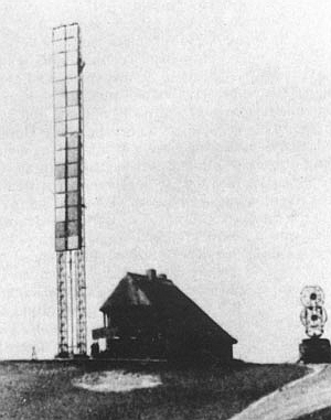
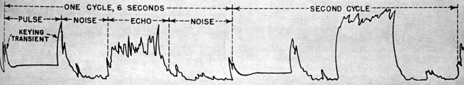
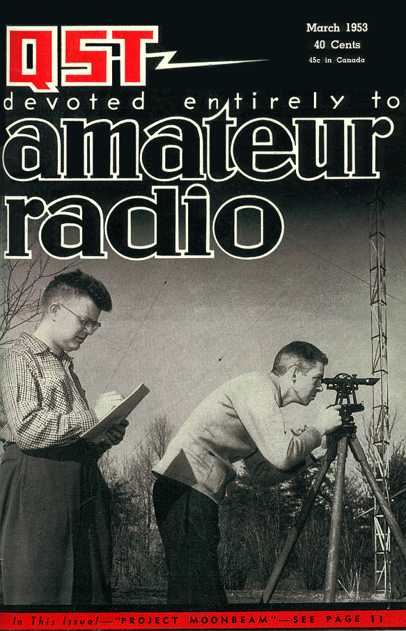
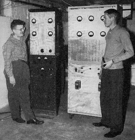
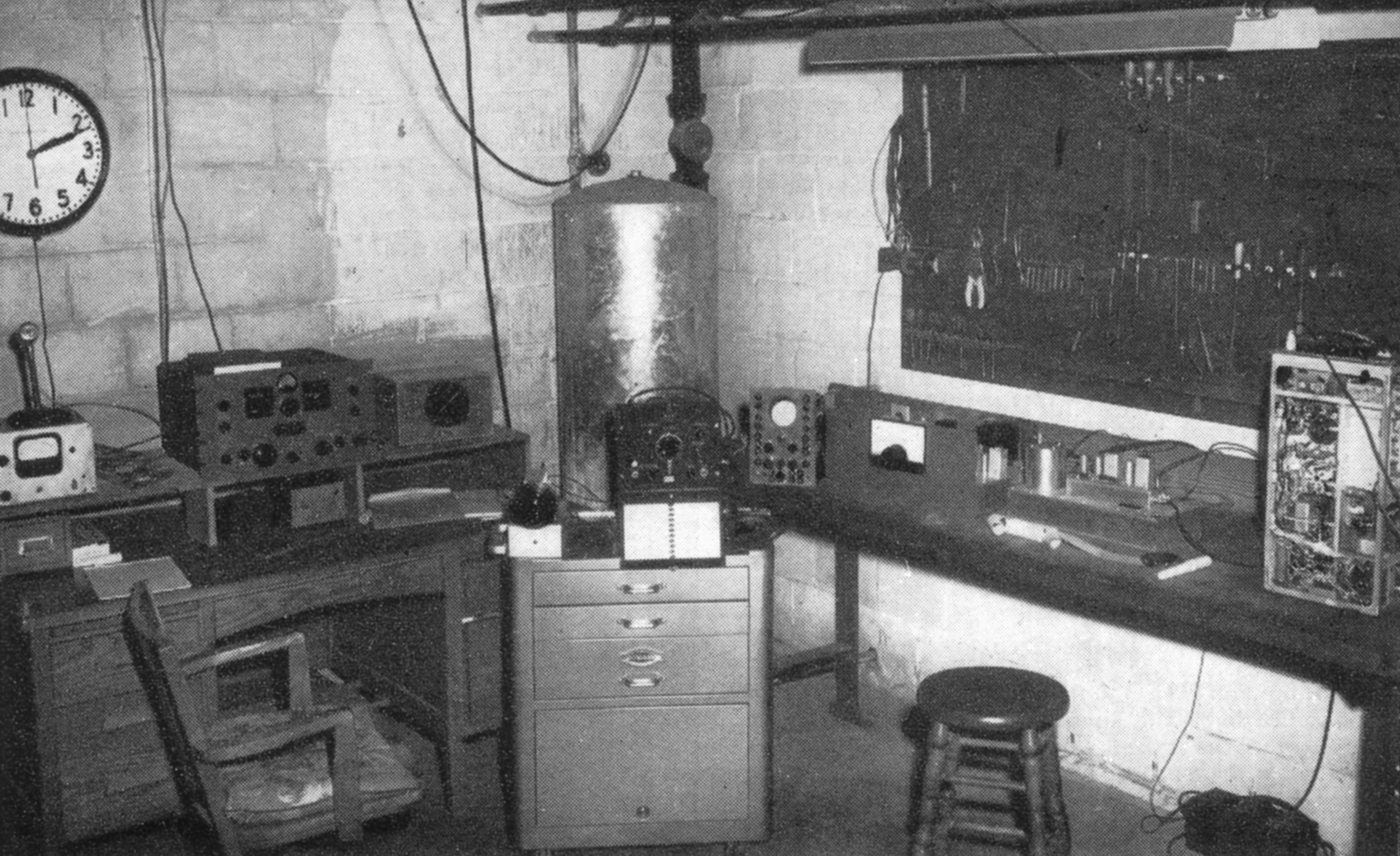

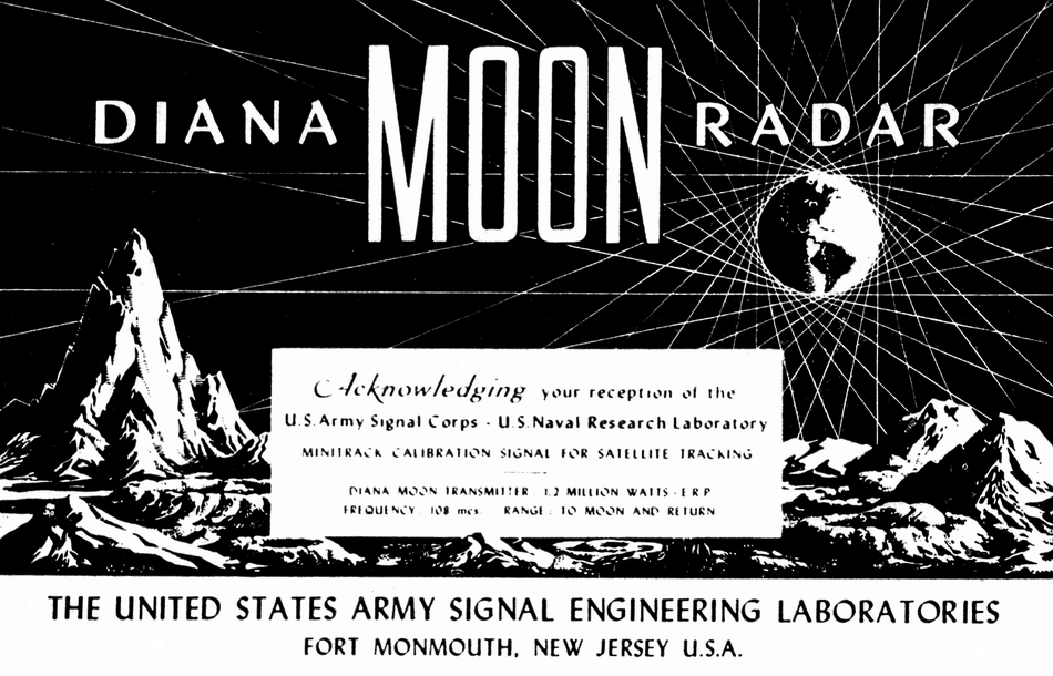
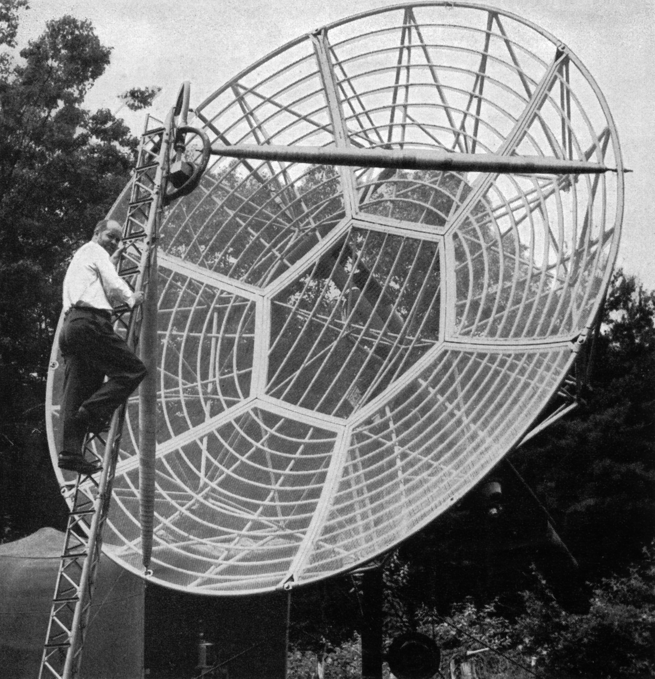
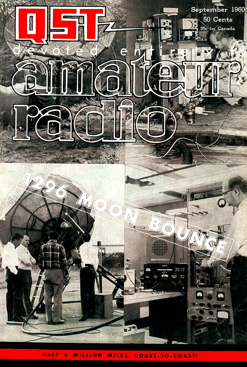
 A
LONG-CHERISHED amateur objective was achieved early in the morning of July
17, when Sam Harris, W1FZJ, Medfield, Mass., first heard a signal other
than his own, reflected from the moon. Four days later the second hurdle
was cleared, and the first lunar QSO by amateurs was on the record. It had
been a long, hard pull for Sam and other members of the Rhododendron Swamp
V.H.F. Society (W1BU), and a shorter but no less spectacular crash effort
by the Eimac Radio Club of San Carlos, Cal. (W6HB).
A
LONG-CHERISHED amateur objective was achieved early in the morning of July
17, when Sam Harris, W1FZJ, Medfield, Mass., first heard a signal other
than his own, reflected from the moon. Four days later the second hurdle
was cleared, and the first lunar QSO by amateurs was on the record. It had
been a long, hard pull for Sam and other members of the Rhododendron Swamp
V.H.F. Society (W1BU), and a shorter but no less spectacular crash effort
by the Eimac Radio Club of San Carlos, Cal. (W6HB).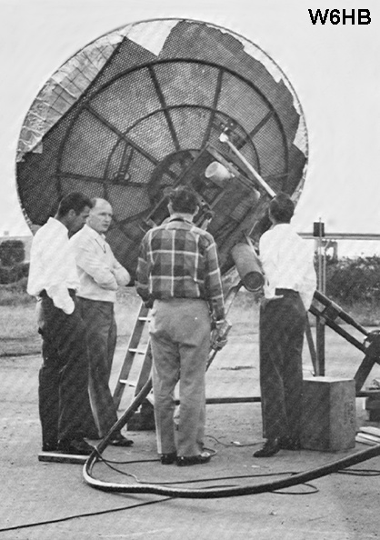
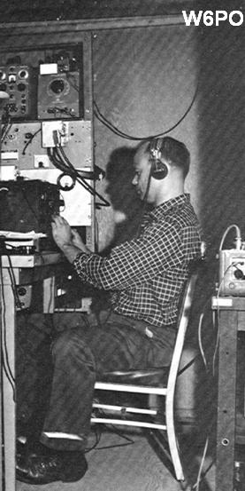
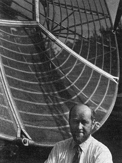
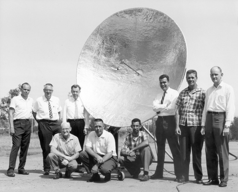
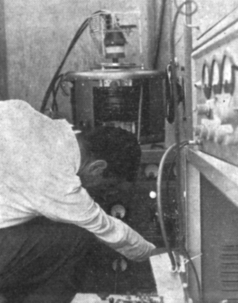
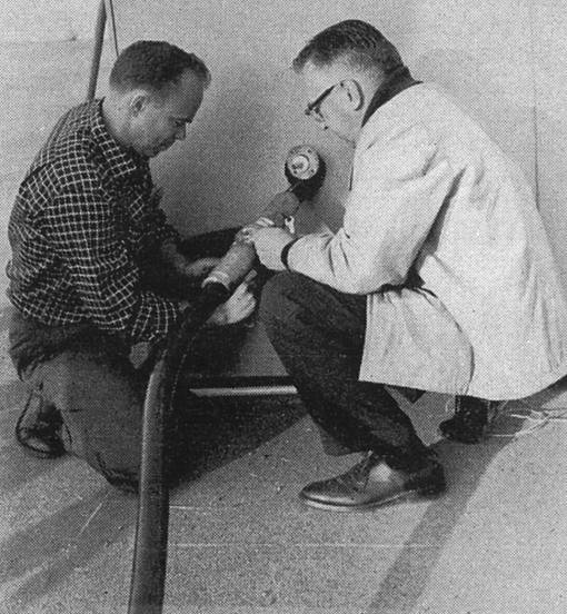
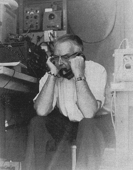
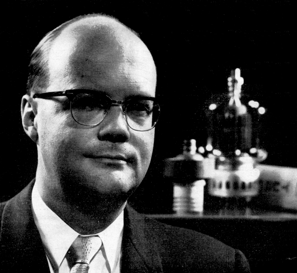
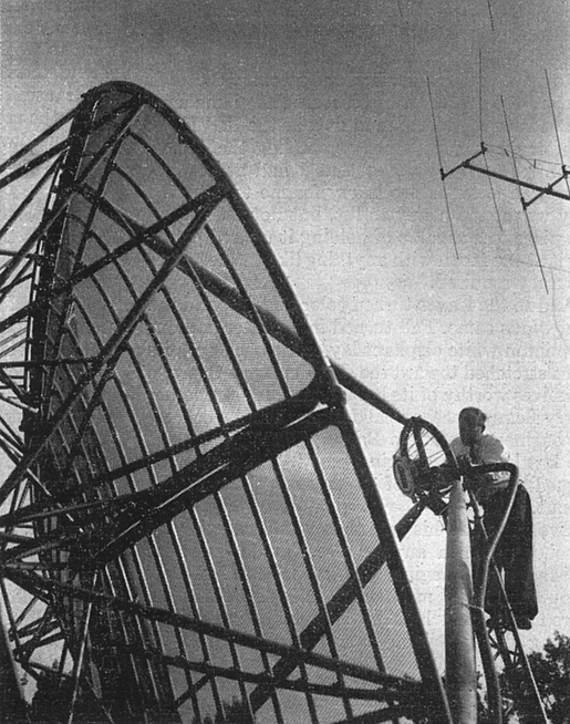
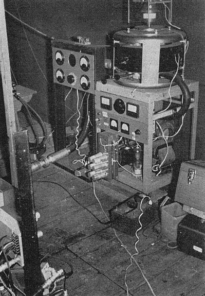
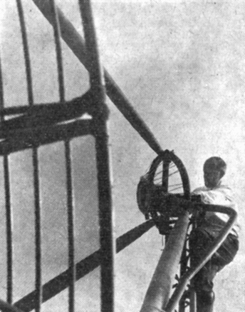
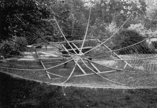
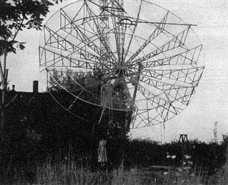
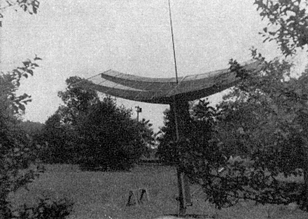 W1TQZ’s 16-foot home-made parabola mounted on
polar mount and ready to feed.
W1TQZ’s 16-foot home-made parabola mounted on
polar mount and ready to feed.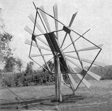
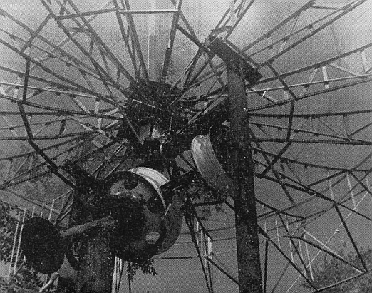
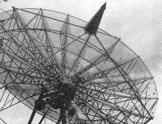
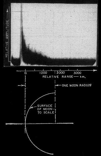
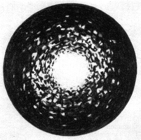
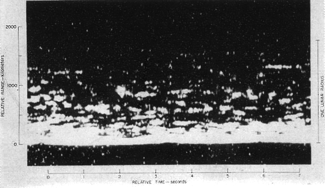
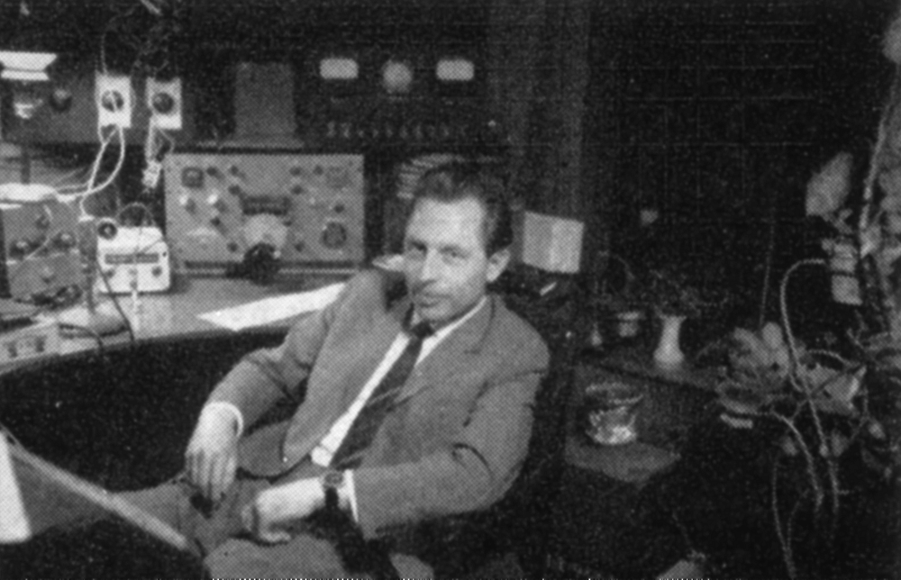
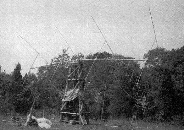
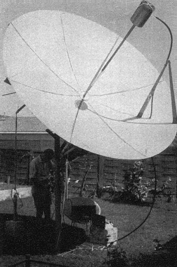
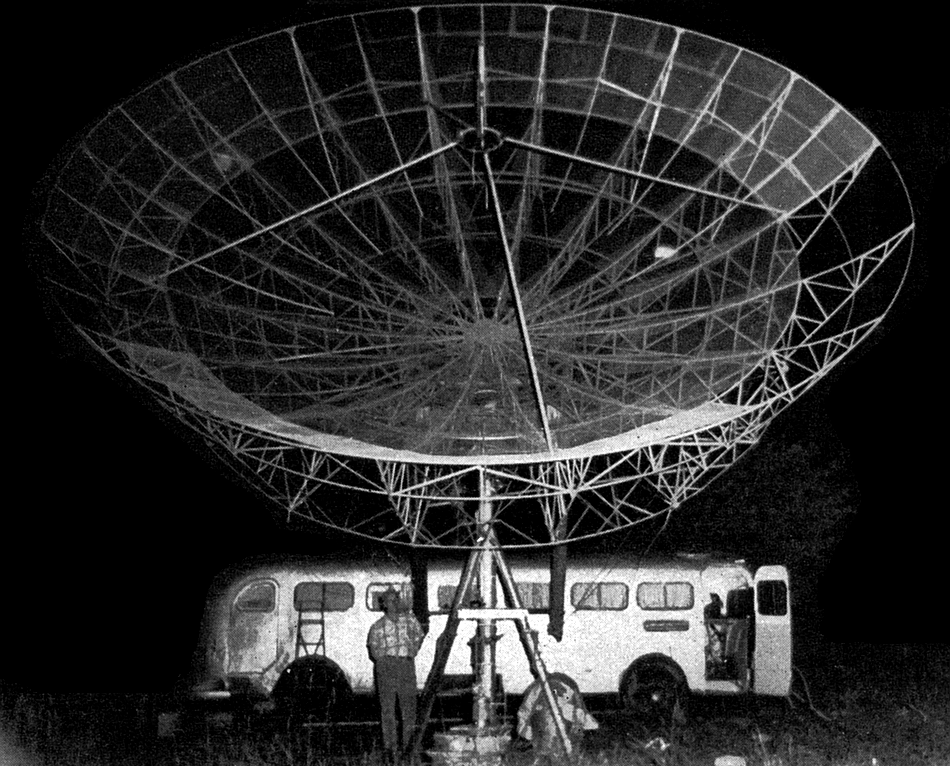
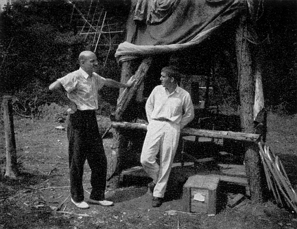
 Apparatus
Noise. Though some noise is generated in transmitters, the most
important components of apparatus noise are produced in the receiving
antenna, transmission line, and receiver front end. This noise is largely
thermal in origin, and results from random movement of molecules. Because
of this randomness it is an excellent approximation to white noise. The
noise power is proportional to absolute temperature and receiver
bandwidth, a relationship usually expressed algebraically as kTB (it is a
proportionality factor, Boltzmann’s constant). Its actual intensity
obviously depends on the equipment in use.
Apparatus
Noise. Though some noise is generated in transmitters, the most
important components of apparatus noise are produced in the receiving
antenna, transmission line, and receiver front end. This noise is largely
thermal in origin, and results from random movement of molecules. Because
of this randomness it is an excellent approximation to white noise. The
noise power is proportional to absolute temperature and receiver
bandwidth, a relationship usually expressed algebraically as kTB (it is a
proportionality factor, Boltzmann’s constant). Its actual intensity
obviously depends on the equipment in use.
 In
our discussion of factors contributing to the signal component of the
s.n.r. we tacitly assumed that the transmitting and receiving antennas
were aimed precisely at the relay point. In the case of some systems, this
is a snap. Were we to have a dipole band, for instance, the antennas could
be left fixed - right at the band - since the band position stays constant
relative to the Earth. Similarly, a satellite in so-called 24 hour orbit
would present no problems. The antenna would have to be aimed but once. In
moon bounce, the problem is not quite so simple, hut it can still be
solved easily, since the moon moves slowly across the sky in a manner
ideally suited to mechanical simulation at very low cost (LeBaron, “A
Home-Built Parabolic Type Reflector for 1296 Mc,” QST, April, 1961).
In
our discussion of factors contributing to the signal component of the
s.n.r. we tacitly assumed that the transmitting and receiving antennas
were aimed precisely at the relay point. In the case of some systems, this
is a snap. Were we to have a dipole band, for instance, the antennas could
be left fixed - right at the band - since the band position stays constant
relative to the Earth. Similarly, a satellite in so-called 24 hour orbit
would present no problems. The antenna would have to be aimed but once. In
moon bounce, the problem is not quite so simple, hut it can still be
solved easily, since the moon moves slowly across the sky in a manner
ideally suited to mechanical simulation at very low cost (LeBaron, “A
Home-Built Parabolic Type Reflector for 1296 Mc,” QST, April, 1961).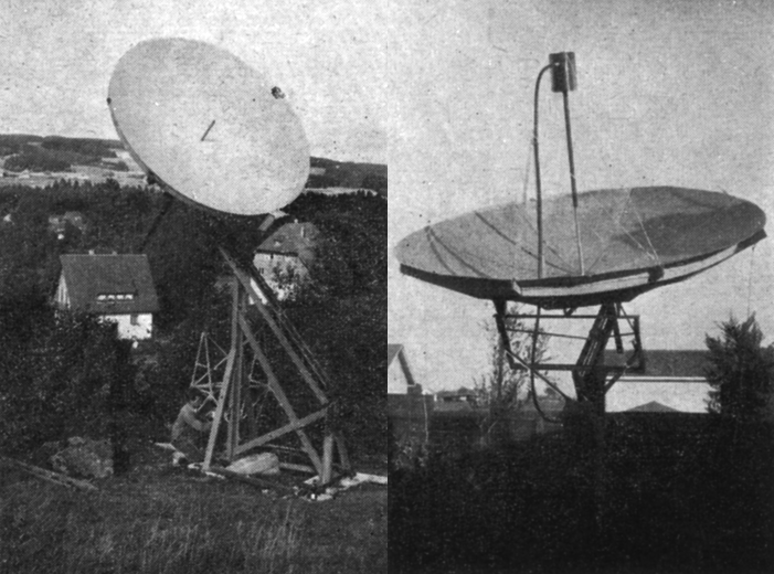
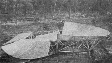
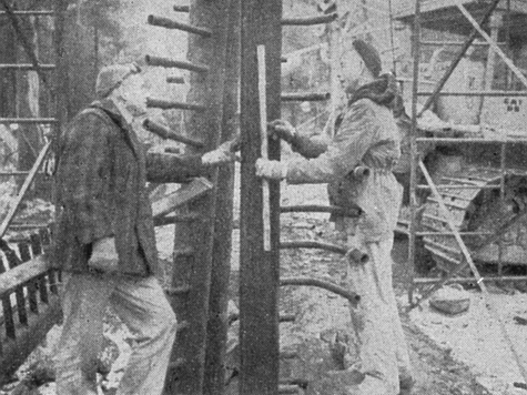
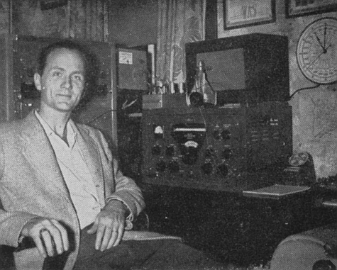
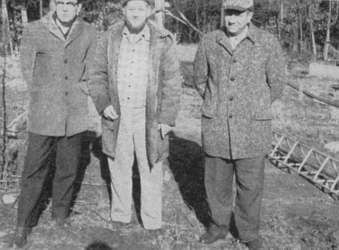
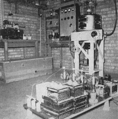
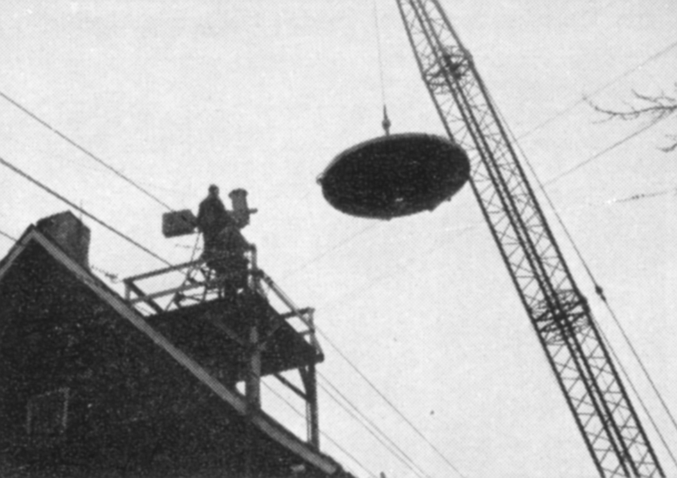
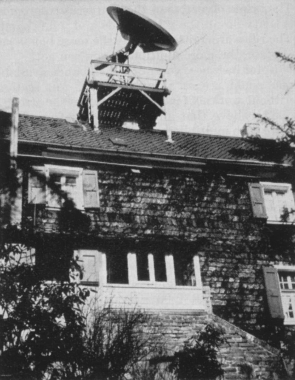
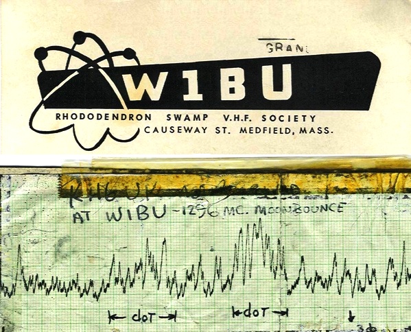
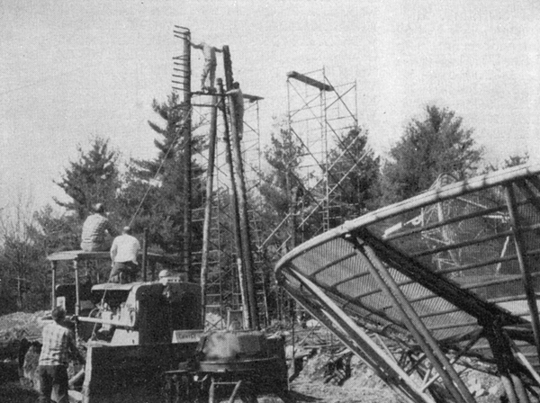
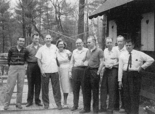
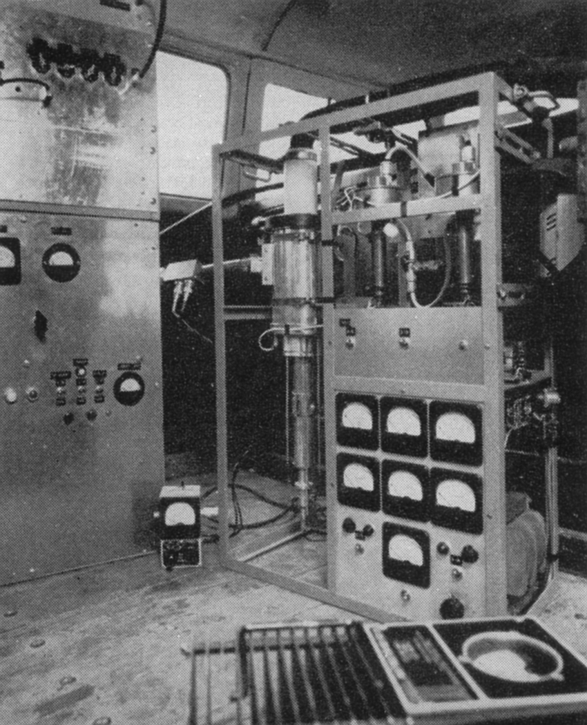
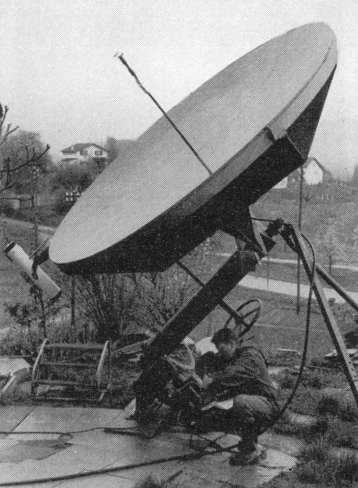
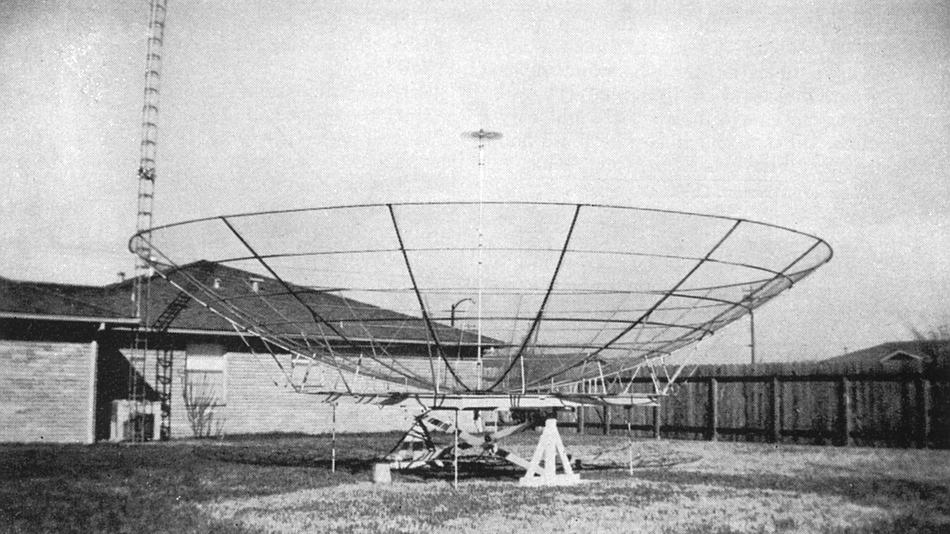
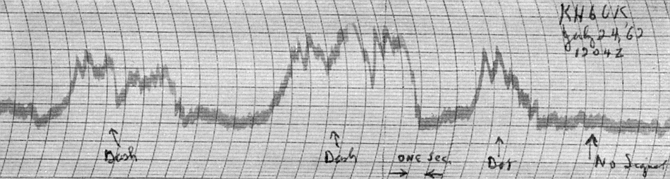
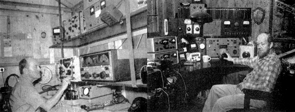
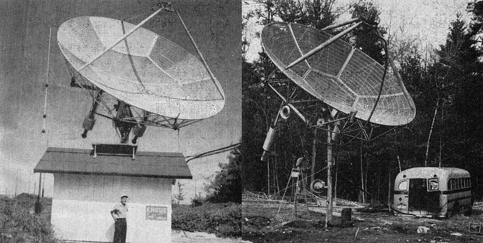
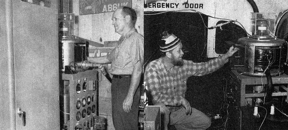
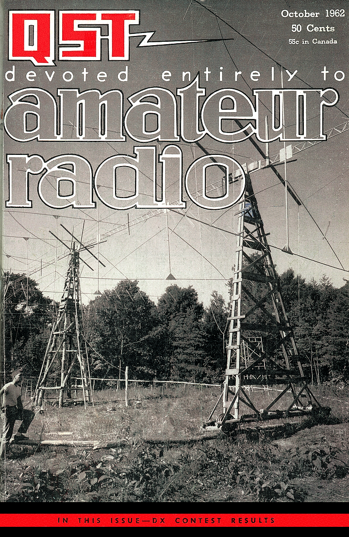
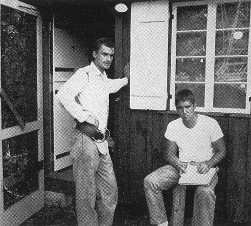
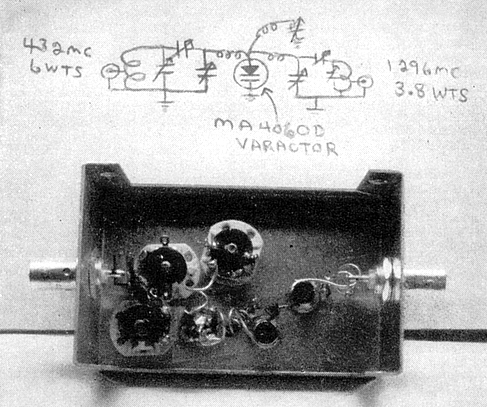
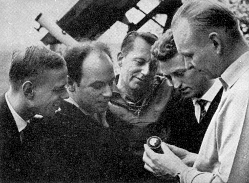
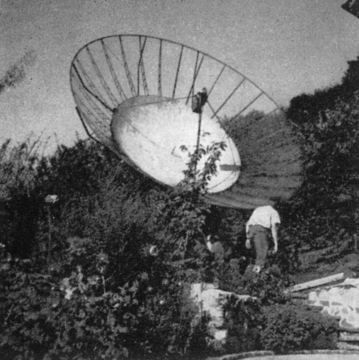
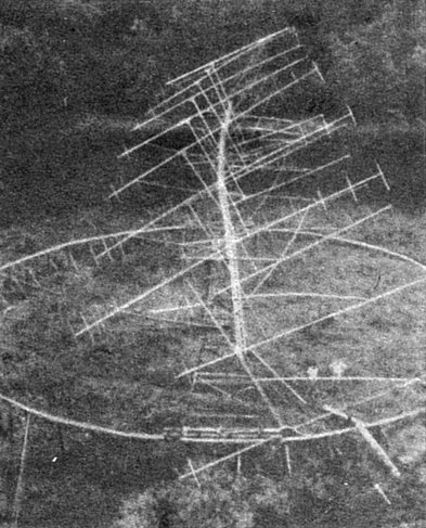
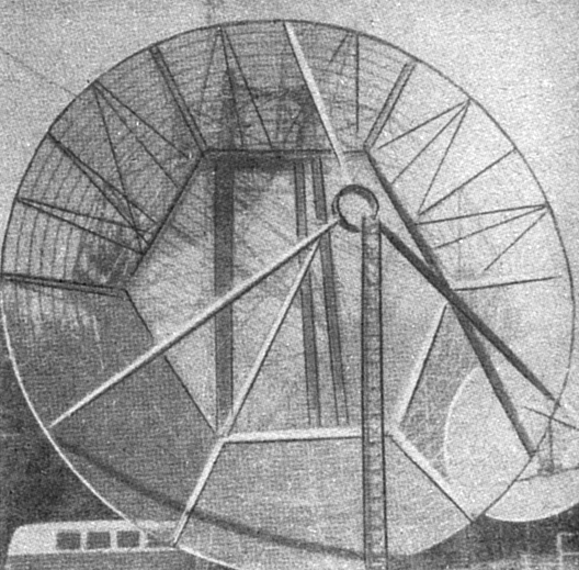
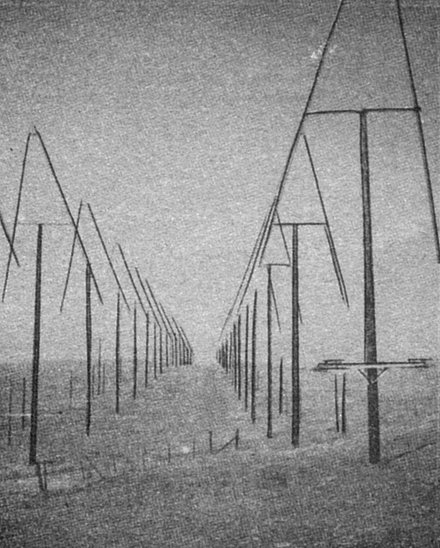
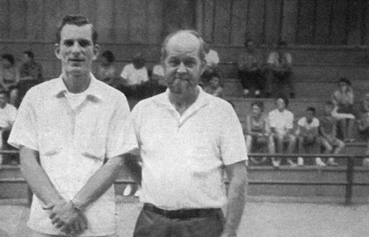
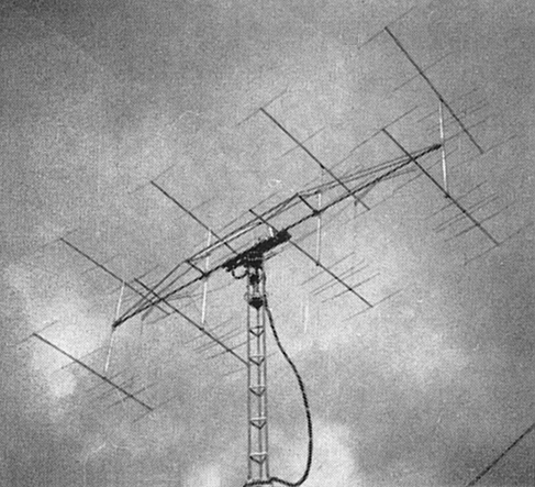
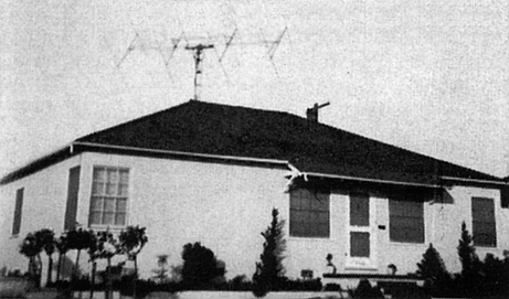
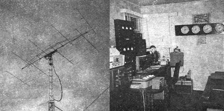
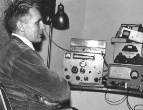
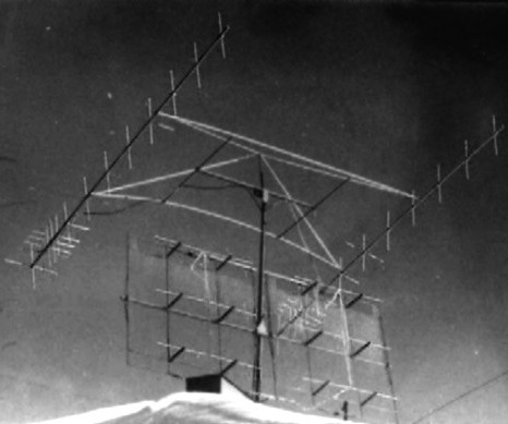 Lenna, OH1NL and his 1964
EME equipment
Lenna, OH1NL and his 1964
EME equipment