|
A few words about RF outputs on Microwaves [2004] Pavel Sir, OK1AIY, ok1aiy@comanet.cz [484 847 099]
As I regularly receive the OK QRP INFO magazine, it occurred to me that I could contribute a little, and readers may be interested in a comparison of past and present performances on UHF and microwave bands. "Output", what a magical word in ham terminology. It can be said that output is a main ham performance criterion; it "sounds good" to everybody, and many hams use it to "treat" their deficiencies in a communication chain as bad QTH, ineffective antenna, or even poor operating skills. But, if we have high enough output we will be able to outcry any other "bungler" in a critical moment which can be unique. This applies to any band generally, and maybe here is the origin of the saying: "There is never enough output ". Output is one of the factors which figure in a calculation formula for a quality contact, and approaching this matter professionally, sufficient output back-up is necessary to make a one hundred percent secure connection which would be stable even when wave propagation drops off, even if this drop off represented a few minutes per year. In our ham practice, we still experience the fact that most contacts can be made with pretty small output, especially using CW and SSB. Then we can talk about QRP, and the fact that we or our counterpart must "strain" our ears to hear each other somehow belongs to this adventure. Hams, who love QRP, are naturally kind and modest, and these are the properties on which the real ham hard-core spirit is based.
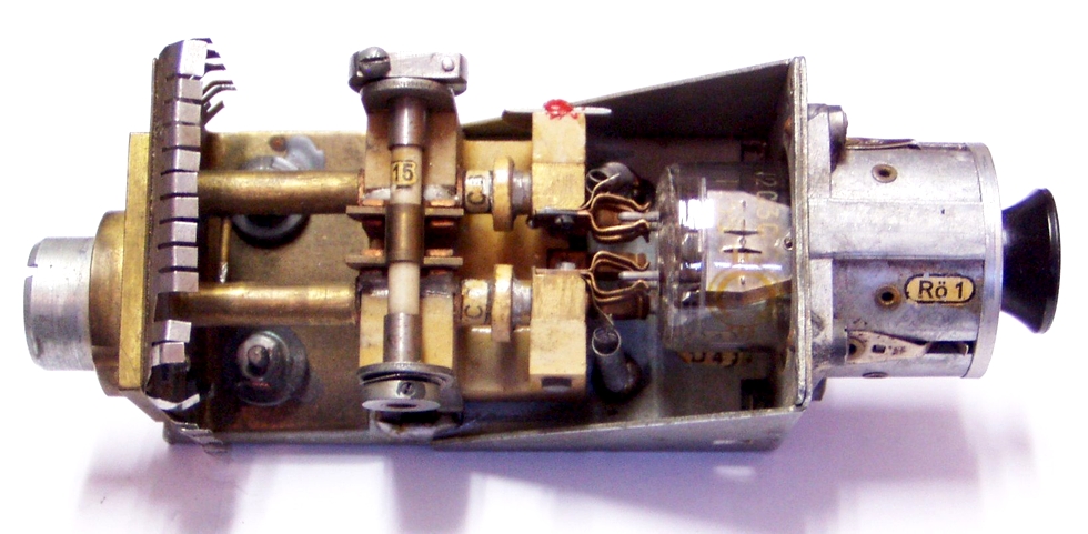
Fig. 1 - UHF solo-oscillator with a LD1 tube (1942)
Let's take a look at what it looked like on UHF. To get a better idea, let's return some fifty years to get the right comparison. Even though transistors had already been known for some time, they were not widespread among hams (and possibilities of their use were limited at that time too), so the tubes remaining here from German army after the World War II were still used. There were several types of vacuum tubes that were used in our branch, and the results that some designers were able to achieve with them deserve our respect even today after so many years. The devices, mostly solo-oscillators or super-reactive transmitters, were built using tubes specially produced, "tailored", for a given frequency and output. For example, the modified and innovated LD7 tube is still produced, and many hams use it in their SW to 23-cm band steam PA's. Just remember the so-called "cheese cake" – RD12Ta and RD2,4Ta. They were produced by TESLA until the 60s under the trade names RC5B and RC5C, and could be used for 300-900 MHz bands and outputs of mW to 1 W. The coaxial triode RCA 5794 was more suitable for the 23-cm band. Readers may know this from thousands of meteorological probes which were scattered by the wind throughout Europe over the last several decades. Companies such as Lorenz, Valvo, Telefunken, Mullard, RCA, Svetlana and TESLA produced dozens of types of beautiful tubes for UHF bands. The devices with tubes were able to provide an output of dozens of watts even above 1 GHz frequency. A radar magnetron of 65 kW for 24 GHz frequency output was once produced. Many ham "old-timers" will gladly remember those times as older ham generations grew up with these devices – after all, there was nothing else to do so with (see fig. 1).
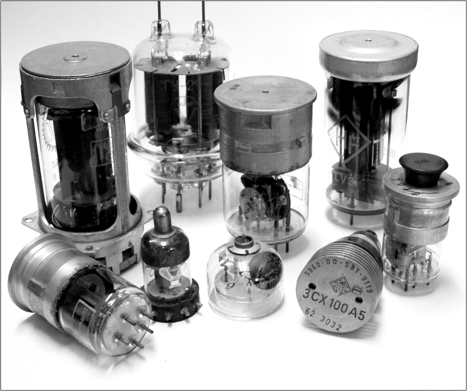
Fig. 2 - UHF and microwave tubes 1939-1980
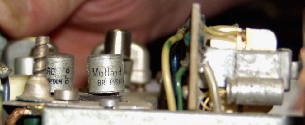
In the 1960s, superheterodyne receivers were used on UHF and microwave bands; tetrodes for amplifiers with a grounded cathode for UHF were developed instead of solo-oscillator triodes, and coaxial triodes were developed for amplifiers with grounded grid (see fig. 2). It is worth mentioning that some tetrodes with short incandescent time were also manufactured - the so-called harp cathode. That meant that during portable operation, full output was achieved within one second of pressing the PTT button. These thermionic tubes faded away as transistors replaced them massively in the late 60s. For hams, the 1960s and 70s were the years of QQE03/12, GU32, GU29, REE30B and RE025XA tubes with outputs of one, dozens or even hundreds watts on 2-m and 70-cm bands. Taking into account the existence of the high-pitched E88CC, EC86 and EC88 tubes which were used on inputs of receivers and continuously good conditions for UHF wave propagation in that period, we can consider those times as a very fertile period for hams. Smaller E180F, EL83 or even 6F32 and 6CC31 tubes were there for QRP lovers. With these tubes it was pleasure to build small transmitters of 1 to 5 W output for 2-m or 70-cm bands, which enabled good contacts. But at that time transistors entered the scene, and because those with higher performance were not always available (sometimes because of price) we tried our chances with anything available. An end stage using two OC171s (by Mullard) provided 10 V at 12 mW output. It resulted in second place at the BBT 1964 Boubin Contest, which was without question an exciting experience (see fig. 3). AFY10 (Siemens) produced hundreds of mW on the 2-m band as well as 2N1141 (Texas Instruments) which maybe served as a pattern for GF501 by Tesla Roznov p. R., which was used in our first reliably operating VXW 010 radio stations.
Fig. 3 - Detail of PA (QRP) with 2x OC171 transistors for the 2-m band (1963)
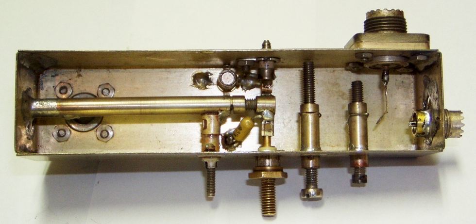
Transistors for the 70-cm band were not available for some time, but a way was found through varactor multipliers. It is true that the same had been used in the professional field for a long time too; the output was amplified at a lower frequency, which was then multiplied by varactors up to 4-8 GHz. Some dozens or hundreds of mW and well-directed parabolic 3-4 m antenna were enough for a TV transmission path. For many years, the varactors for the function (and the capacity diodes for channel selectors) had been the only elements we could use to reach higher frequencies. The designs were successful, and I really enjoyed this period. In 1965 the first semiconductor device for 432 MHz was built – the BA121 diode capacitor produced about 5 mW, and the first connections were established with OK1BP from Chrudim and OK1AI from Bohdanec. The first multiplier using BA149 produced about 20 mW on the 23-cm band, and using KA204 by Tesla Piestany it was possible to get considerably higher outputs (see fig. 4). KA204 transistors were also used to build the first 2304 MHz device. Though the above-mentioned diode capacitors are used only for TV tuner tuning, some of their electrical features were comparable with varactors designed as frequency multiplying and directing devices. They could multiply and simultaneously mix SSB signal from 2-cm or 70-cm bands; that is how the first 10 and 24 GHz device was built (though its output was counted only in micro-watts). But not to skip anything, in 1975 the HT323 tube (equivalent of 2C39BA and 3CX100A5), which was produced in the former DDR (East Germany), appeared, or to put it in a better way, it became available. This triode is suitable for 23 and 13-cm bands; its 100 W plate dissipation enables an output of some dozens of watts on these bands (see the foreground, fig. 2). Now, it has been replaced by LDMOS transistors, which can produce hundreds of watts, and which are so small that several of them can be put into a matchbox. This represents an enormous output, but even high outputs do not "save the day" during some contests in Europe, where thanks to worse conditions, QRV stations can hardly be heard. If there were good conditions, contacts could then be established even with very low outputs. The introduction of the gallium-arsenide field controlled transistor (GaAsFET) was, without a doubt, a breakthrough in professional and consequently amateur microwave device design.
The technical parameters of devices
were simplified and enhanced, first with receivers, later also with power
transmitters. I remember the first miliwatt on the 3-cm band and the first SSB,
280-km contact. It was clear what opportunities these bands could provide us
with – but that was in 1984, with all the things which belonged to that era…
Fig. 4 - 432 / 1296 MHz varactor multiplier with KA204S (1973)
Quickly progressing technology made available new and cheaper parts even for our designers. The 6 and 9-cm bands were assigned for our experiments, and it was my pleasure to build at first simple then more sophisticated converters of initial outputs of a couple of mW (the first OK-HB QSO with HB9MIO was achieved at only 6 mW). The 9-cm band is excellent in this regard. The frequency of 3400 MHz is just as "low" as necessary to enable good functioning of amplifiers. At this frequency, coaxial cables and connectors have tolerable attenuation, and various antenna relays can be used without "killing" the signal completely. The same applies for antennas and for the construction itself. This is a good training band for higher frequencies. Only microwatts of output were necessary to establish an SSB connection from Benecko to Klinovec (cca 200km). The 24 GHz band is also interesting. The first devices produced just microwatts until ten years later, when several dozens of mWs were achieved. To build a homemade device with an output higher than 50 mW represents a problem even today. The TOSHIBA BA2160B pro amplifiers of output higher than 1 W enabled progress. Traveling wave tubes for these bands already exist, and outputs as high as dozens of watts enable even EME contacts. Though there are few of them in the world, OK1UWA from Plzen can boast one. So far, an output of 10 – 20 mW has been achieved on 47 GHz (frequency 47088 MHz) using a sub-harmonic mixer; the distance achieved was 96 km.
The output is even lower on the 76 GHz
band (frequency 76 032 MHz) – (maybe just in single μW). The distance achieved
is 13 km for the time being. It could be extended, but we at OK1UFL have not yet
found the time to do so. The last is the 241 GHz band (frequency 24 1192 MHz). The device is similar to those for 76 and 145 GHz bands, and the output produced by the HSCH9101 tube, which works as a ten-fold multiplier combined with a mixer, is quite infinitesimal thanks to its high multiplication rate. So far, the limit distance is only a few meters. As you can see, this is a real QRP, and believe me if we’d had available the right components for a little bit higher outputs, we would already be performing better. Some longer contacts have been achieved abroad (most of them recently). Just one mW of output more on the last four bands and we would be a step ahead. Finally, let's ask ourselves what the QRP output should really be? Is it 1 W or maybe 10 W? From the point of view of present allowed outputs, it could be even more. Perhaps we all feel that it is often over designed, and therefore I leave the end open for your comments. OK1AIY
Note of OK1TEH: In EME world is common to define QRP category due to station EIRP as it's shown in an example of rules for Dubus /REF contest:
For OK2KKW web rewrote and edited by Matej, OK1TEH in year 2010. Tnx for permition to Pavel OK1AIY and Petr OK1DPX
More links: http://www.ok2kkw.com/next/13cm1959.htm http://www.ok2kkw.com/kv1952/23cm_ok1kw1952.htm http://www.ok2kkw.com/kv1949/23cm_rx1949.htm |