Version 6.51
OK1DIX (c) 2020
Contents
1. VUSC - VHF/UHF/SHF/Contest for Windows
2.
Technical prerequisites
3.
Installation
4. List of files
5. Program start
6. Contest operation
7. Contest evaluation - log creation
8. Database maintenance
9. QSL maintenance
10. CW/SSB control
11. Network operation
12. Network – installation and
configuration
13. TRX control and band switch
14. Packet radio, DX cluster, ON4KST chat
and posting results to SloVHF web
15. Communication with the program
AirScout
16. Sound recording
17. Rotator
18. Appendix - schemes and pin-outs of
the interfaces and adapters
1. VUSC
- VHF/UHF/SHF/Contest for Windows
This program has
been developed
for the VHF/UHF contests as a successor of the previous
MS-DOS version. Operator experiences of contest stations OK2KKW, OK2A, OL4A,
OL9W, OK1KUO, DM7A,
IZ4BEH, PE9GHZ and others have been used for its development. The
program design is similar to the contest program N1MM. Of course any ideas for
improvement are very welcome. Currently there are English, Czech and German program
versions including the relevant manuals. You can also check out the VUSC Web page
http://www.ok2kkw.com/programs.htm for
latest updates and news.
2. Technical prerequisites
The program is designed for using on the PC with operating system
Windows XP/Vista/7/8/10. Program
in not supported on Windows 95, 98, Me,
NT and 2000.
Hardware requirements:
· Processor: at least Pentium III
· RAM: at least
256 MB may vary
depending on the databases size and number of QSOs
in a contest
·
Free space on hard disk: about 30
MB, depending on databases size, apart from recorded sound files.
· Ports (optional): serial RS-232C (COM) (CW keying, elbug paddle, rotator control, TRX,
band switch control),
parallel Centronics (LPT)(CW keying, elbug paddle, rotator control, band switch control),
USB (rotator control)
· Sound card
(optional)
· Network card
(optional)
· Display resolution: at least 1024x768, optimal 1280x1024 and
higher
Software
requirements:
· Windows XP/Vista/7/8/10
with DirectX 9.0c or higher
· LINX DLportIO Driver,
optional, only for keying/paddle or rotator and band switch
control via parallel port LPT (valid only
for 32 bit Windows)
· MBUSB Driver,
optional, only for the rotator adapter on
USB port with PIC, see the
chapter 17
on the
rotator control
(valid only for 32 bit Windows).
· Arduino UNO
R3 driver for the rotator adapter, optional (see the
chapter 17 on the rotator control)
RAM
size and disk space depend on the database size and recorded sound files. Author
will appreciate any feedback concerning program usage on different PCs and
Windows versions.
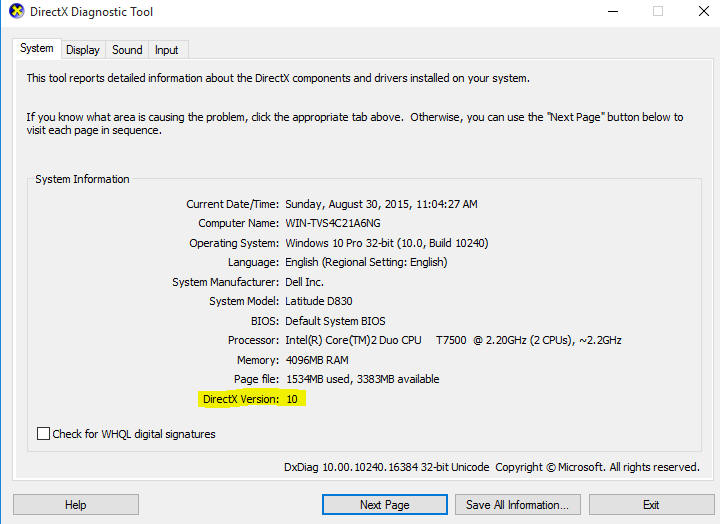
3. Installation
Check the version of DirectX first. A suitable version of DirectX is
available on Windows Vista, 7, 8 and 10. If you install on Windows XP check
it beforehand by running the
program dxdiag.exe, usually located in C:\WINDOWS\SYSTEM32 or C:\WINNT\SYSTEM32. If
there’s no DirectX or the version is older than 9.0c download it from
http://www.soft32.com (search for the
"DirectX 9 Redistributable").
A new installation of VUSC is
accomplished by double-clicking on the self extracting archive file
VUSC_setup_en.exe. The
entire installation directory path must NOT contain any
spaces, dots or hyphens!
If you intend to
use the LPT (parallel) port for CW keying, band switching or rotator control, install the
DLportIO driver by running Install.exe in the subdirectory DriverLINX\install after the
VUSC installation.
If you intend to use the PIC adapter for the rotator control install the MBUSB driver for the
PIC.
These two options are available only on 32bit
Windows, though. The driver for the rotator adapter with Arduino
usually installs
automatically with some exceptions (see below the chapters
17 and 10
on the rotator control and CW/SSB control for details). If you
intend to use Microham for keying and/or TRX control you have to install the
Microham USB driver (a very
confusing name as it's much more than a driver, see the Microham
documentation).
If you perform an
upgrade of the previous version it's better to get a special upgrade archive file
VUSC_upgrade_<version number>_en.exe. If you experience problems with the program
start after the upgrade replace the file vuscwin.cfg in the installation directory by
the vuscwin.cfg from the subdirectory data or use one of the templates
vuscwin*.cfg
suitable for your display resolution (see below). In this case you have to
renew your individual settings (CW/SSB memories, windows layout etc.,
see below).
In rare cases there may be a problem with the (optional) driver DLportIO.SYS after the
installation of some Windows XP system updates. For an unclear reason the update installation program
changes the registry database entry for the DLportIO driver which causes driver load
failure at VUSC start. The remedy is as follows:
Go to Start->Run type into the box regedit. Go to then to the folder:
HKEY_LOCAL_MACHINE\SYSTEM\CurrentControlSet\Services\dlportio
Open it with double click and change the value of the key Start to 2 (the original
value is usually 3). Check also if the file DLPortIO.SYS is in the directory under the key
ImagePath (usually C:\Windows\drivers). Close the regedit and restart your
PC. If the problem persists try to change the key value to 1 and reinstall the driver.
CAUTION! Make sure that you’re really changing just the key
Start as
described above. Some unintentional
changes in the
registry database may corrupt your Windows. If
you don’t feel sure about this ask someone experienced for help.
If you want to
uninstall the VUSC program from your PC simply delete the installation directory and the
relevant shortcut. As the program doesn't make any use of the Windows registry database
it's not necessary to uninstall it in the Windows control panel.
4. List of files
The complete installation contains following files:
· VUSC.EXE - contest program
· VUS_BASE.ASC - ASCII call/locator database file sorted by stations
· VUS_BAND.ASC - ASCII call/band database file sorted by stations
· VUS_BASE_DEF.ASC - default ASCII database file sorted by stations
·
OWNH.HDR - stored individual data of the log header sheet
· QSL_BASE.ASC - QSL database ASCII file
· CONTLIST.TXT – list of evaluated contests
· QSLTEM.HDR - QSL label form
· VUS.HDR - log header form for contests evaluated by distances
· VUS2.HDR - log header form for contests evaluated by locators/multipliers
· VUS3.HDR - log header form for Nordic Activity and Tesla Contest
· QRBPAT.DAT - file containing the point pattern for the evaluation by locators
· VUSC_EN.HTM - English documentation in HTML format (with
graphical files in GIF format)
· VUSCWIN.CFG - configuration file containing CW memories, port settings and other
technical parameters, window layout, font setting etc. There are also configuration file
templates for various display resolution vuscwin1024.cfg, vuscwin1280.cfg and
vuscwin1600.cfg to make the setting easier.
· QUICKSTART.CFG - configuration file with the same structure as VUSCWIN.CFG used for the quick restart.
· ROTATOR.CFG - rotator configuration and
calibration.
· TRANSCEIVER.CFG - configuration file with
the TRX parameters
· KEYER.CFG - configuration file with
the keying/audio interface parameters.
· RIVER.PNT, ISLAND.PNT, COAST.PNT, COUNTRY.PNT – Files with the
direction map data.
Following files are created while working with the program. They are mostly located in the
subdirectory of the same name as the contest.
· #######.DIX - contest file (located in the main directory)
· #######.BIN - work file (located in the main directory)
· #######_$$$.LOG - log file from one band
· #######_$$$.EDI - contest log file from one band in EDI format.
· @@%%%%%%.EDI -
contest log file from one band in EDI format for sending by e-mail named according to the
general contest rules (located in the main directory)
· #######_$$$.LDB - sorted list of calls with their locators from the relevant band.
· #######_$$$.SUM - summary sheet of one band (calls with their contest numbers) as
required by some contest rules.
· #######_$$$.QSL - file to print on QSL labels
· #######_$$$.ADI - file in ADIF format for upload to eQSL, LoTW etc
· #######_$$$.REM
- list of QSOs with remark
· QSL_BASE.DAT - QSL binary work file
· Subdirectory ####### for storing of logs, sound files, work file backups and other
contest specific files. Only the files ######.DIX and @@%%%%%%.EDI are stored in the main
VUSC directory.
Symbol legend
####### - stands for the name of the contest
@@ - category
number according to the general contest rule
%%%%%% - own
callsign
$$$ - three
characters band code:
144 - 144 MHz
432 - 432 MHz
129 - 1296 MHz
232 - 2320 MHz
340 - 3400 MHz
565 - 5.6 GHz
10G - 10 GHz
24G - 24 GHz
47G - 47 GHz
76G - 76 GHz
120G - 120 GHz
134G - 134 GHz
248G - 248 GHz
5. Program start
Before the start you should check the right local time and time zone setting
in Windows
(Control panel -> Date and Time). It’s not necessary to
set UTC time on your
PC provided the system time and the local time zone
settings (including the daylight saving option) are correct. The program
allows later time corrections, but you avoid troubles and additional work if
you start with the right time and zone.
On Windows XP start the program by double clicking on VUSC.EXE file or
on the shortcut on the desktop.
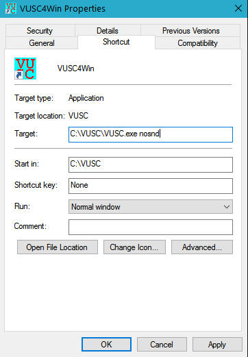
On Windows Vista/7/8/10 use the right mouse click and choose "Run as
Administrator". You also can set this permanently by right clicking
and setting the VUSC.EXE properties as follows:
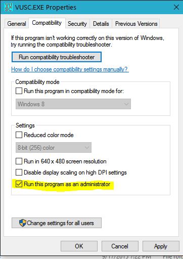
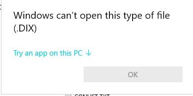
If the
attribute "Run this program as an administrator" is set you can also start
the program by double clicking on a file with .dix extension. In this case
the program starts in the normal mode (no quick restart) and opens the
contest from the .dix file. The following
popup window appears after the very first start:
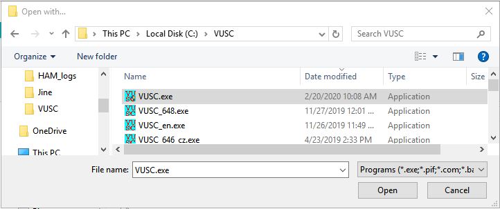
Expand
the application list and find the file VUSC.exe in the VUSC installation
directory:
When starting the program by this method next time the following popup
windows appears:
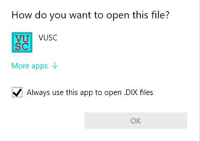
If you leave the check box checked the
assignment of the .dix files to the VUSC.exe becomes permanent, no popup
window appears any more and the .dix files get the VUSC icon. CAUTION! Also in
this case the entire directory path to the .dix file must not contain any
hyphens, spaces or dots.
If the program is launched directly (i.e.
no double click on a file) a small popup window appears with the question
"Quick restart?". Normally respond "No". "Yes" is only for fast renewing of
the previous state (see below).
The program is designed for minimal display resolution 1024x768 pixel.
The optimal resolution is 1280x1024 or higher. The
windows layout and fonts may not be quite optimal
after the first start, but you can change the size, layout
and fonts ("Options->Font") of all windows to match them to your display and
individual needs. When choosing the fonts of the log grid choose one of the non-proportional fonts, so
the cursor position always fits to the character. The most common non-proportional fonts
are:
Andale Monospace, Arial Monospace,
Consolas, Courier, Courier New, Letter Gothic, Lucida Console, OCR-A, OCR-B, MICR,
Typewriter, Typewriter Elite, Typewriter Gothic.
Also choose the fonts of the column headers so the fonts of
the log grid match the column width.
As the setting of suitable fonts and window layout may be difficult for an
inexperienced user, four sample configuration files (vuscwin1024.cfg,
vuscwin1280.cfg, vuscwin1400.cfg, vuscwin1600.cfg) are supplied
with the program for various display resolutions. For a new installation you
can copy
the one suitable for your display resolution under the name
vuscwin.cfg and use it as a start point for your own
configuration. You also can
change the windows layout
for different display
resolution dynamically at runtime by choosing "Options->Resolution<number>".
It sets the windows layout
and fonts as set in the relevant pre-defined configuration file (vuscwin1024.cfg,
vuscwin1280.cfg, vuscwin1400.cfg, vuscwin1600.cfg) or you
can specify a configuration file if you choose "Options->Resolution->User".
You can have more configuration files stored in the working directory for
different situations (for example number of displays, specific resolution
etc.). You can
also use
this option to renew the
proper layout if a window "disappears" or other
problems with the windows layout or fonts occur.
The configuration files contain many other parameters (see below), but
only the windows layout and fonts are set in this case. Other current
parameters remain unchanged.
You can close most
of the windows you don't need by clicking on the cross in the title bar. For technical
reasons some windows are permanent and can't be closed. Closed windows appear again
at
the program start. All windows can be minimized in an icon by the right clicking on
their
title bar and choosing "Minimize". If the configuration is saved
by "Contest->Config->Save" the
windows stay minimized even after the restart. The minimized windows can be restored to
their original size and location by double clicking on the icon.
All settings (including the
windows layout and fonts) are preserved in the configuration files
vuscwin.cfg
and
quickstart.cfg (details see below).
If you terminate the
program with "Contest->Exit" the current configuration setting is
automatically saved in the file vuscwin.cfg for the next start. The
configuration can be saved also explicitly by using "Contest->Save config".
If you choose "Quick restart" at the program start, the configuration file quickstart.cfg
is read instead of vuscwin.cfg. This file contains the
current configuration of the running VUSC
including the
open contest, network connections, displayed
bands, network messages, to-do list,
rotators etc. to
renew the latest state. This option is usually used during the
contest if you need to restart the PC, after Windows crash or similar
problem. When
configuring the TRXs, rotators and keying you can use the option "Contest->Config->Display
technical parameters" for better overview of used ports and other technical
parameters.
In rare cases the
program may crash after the start. A bug in the sound card driver was
identified as a
most common reason. The driver crashes when a DirectX function is called. In such a case
start the program from a command line "Start->Run" with the
argument nosnd from the command line:
vusc.exe nosnd
or modify the program shortcut as follows:
It switches off
the sound card entirely. The sound card functionality (SSB CQ
call, CW monitor and audio recording) is disabled, but
the CW keying functionality is retained.
There may be the
DLPortIO driver already installed on some installations of Windows 8 and 10
(typically on those upgraded from previous versions and on 64bit systems)
for VUSC or another application. This may cause VUSC to crash when starting
as VUSC is a 32bit application which does not comply with the 64bit
DLPortIO.dll. You can either uninstall the DLPortIO driver from the Windows
(if you don't need it for any other application) by renaming or deleting the
file DLPortIO.dll in the Windows system directory or starting VUSC with the
parameter nodlp in the same way as with nosnd.
6. Contest operation
If a contest was not opened at the start by double clicking on
the file .dix either open a new contest by the menu
command "Contest->New" or open an
existing contest file with "Contest->Open". Following file formats can be
read: VUSC specific format (extension .dix), EDI format (.edi) or
a crash recovery file (.bin). These file types can also be merged with an open
contest using the option "Contest->Add". In this way you
can merge logs from different bands if the PCs were not connected by the
network. A text file ("*.txt") can also be added to an open contest. The text line format must look as follows:
<YYMMDD> <HHMM> <Call> <RST> <QSO number> <Received
RS(T)> <Received number> <Locator>
Field delimiters are any number of spaces and/or tabulators.
CAUTION when adding a file! If there are QSOs with the same
number on the same band in the file they will be overwritten in the log!
When opening a new contest enter
the contest name, contest (evaluation) type, own locator and the
contest callsign. There are following
supported contest (evaluation) types:
- Distances
- Locators w/o
multipliers
- Locators with multipliers
- Czech Activity
-
Nordic Activity
- AEGAN Contest
- AGCW Contest
- Tesla
Memorial
- Dutch Activity
- MOON
Contest
-
Swedish Nordic Activity
If the contest
type is "Locators with or w/o multipliers"
you can redefine the points for
the locators by using your own locator pattern file. Check the file QRBPAT.DAT
(evaluation of the Czech Activity Contest) as an example
The old
.dix
files from the MS-DOS VUSC version higher then 4.03 can be opened, but they are
automatically converted to the new Windows format when saved and can not be used by the
MS-DOS version any more.
The program VUSC has primarily been designed for on-line usage by the
operator in the the contest; no paper log
is needed. For that purpose the contest data are secured, so they don’t get lost even if the
program and/or computer crashes for any reason. Only the last QSO currently being entered
may get lost. In such a case
either use the option "Quick restart"
or open the relevant contest file
with the extension .bin. If a .bin file with the same name exists in
the same directory when opening a .dix file (i.e. the program was not
correctly closed) a warning message is issued and you can decide if you want to read the original file or the crash recovery copy
containing the most recent state. This applies for the quick restart
as well.
Before any major change in the log (for instance adding another contest
into the open log, saving a contest etc.) a copy of the .bin file is saved
in the contest directory. Last five copies are retained. In addition you
can write backup copies (for instance on a flash disk) at any time during the contest by
using the command "Contest->Save
as" or program automatic periodical backup copy in
the menu "Options->VUSC".
The log has a classic form. It means that the QSOs are entered as they have been made in time
on all bands.
(the same approach as in the CT contest log from K1EA
or WinTest). There are usual fields like time, call, QSO number, report, received code
and locator. The field MP indicates a multiplier, RM a remark to the QSO and
M indicates the mode. All fields
including the QSO number can be changed at any
time also in the previous records. Be careful,
though, when manipulating QSO numbers because the other
stations have them already in their logs. Also avoid putting higher QSO
number before the lower one or entering two or more QSOs with the same
number on a band as it
may overwrite existing QSOs
especially when the network
is active.
In the MOON Contest where the QTH name is a part of the exchange the remark
window automatically pops up with the # (hash) as the first character after
hitting <ENTER>. This indicates that the text is the QTH name instead of the
remark. You can use CTRL/N as for the normal QSO remark any time if you need
to reopen and change the QTH name, but don't delete the hash character at
the beginning otherwise you lose the extra points for the QTH.
Normally you move over the input fields using SPACE
(right) or TAB (left) key. Another option is to invoke a
special typeahead window ("Options->Typeahead"). The data can be typed there in any order and entered
with the RETURN key similarly as in the programs TACLog
or Atalanta. The program
automatically distinguishes the data type, which is also indicated in the lower part of
the typeahead window. If the automatically determined type does not fit it can be changed
with the SPACE key.
After bad experiences with too restrictive input data checks, the program
allows entering double and/or incomplete QSOs. All data can be changed at
any time and all changes are immediately reflected in the entire log and
also updated on other computers (nodes) in the network if it's used. For
faster data entering it is possible to omit the callsign prefix and report
59(9). Also the first two letters of a locator if omitted are automatically
extended, first according to the callsign prefix, then (if the prefix is not
found) according to boundaries of one big WW locator
(i.e. the locator defined by the first two letters)
around your own QTH. There
are following parameters in the "Options->VUSC"
for this:
"North-South default border"
and "East-West default border" - big WW
locator extension boundaries
"Default prefix" - callsign extension.
"Length to expand the QSO #" - the number of characters from which
the report and QSO number are expanded.
To avoid
unintentional data change (especially by inexperienced operators when working in the
network) you can lock the entered QSO. In such case a confirmation of the warning message
is needed to log the change.
If not entered manually the
current UTC time is automatically supplied for the QSO
provided the time and time zone are properly set in Windows.
Check the "Date and time" setting in the Windows "Control panel". If you work in the network
the clock must be synchronized on all PCs.
It’s
absolutely necessary to synchronize time on all
nodes in the network using "Network->Band to synchronize" before
entering any QSO.
Otherwise the data may be lost or damaged! See the
chapter 11
on the network operation for details.
If you enter the QSOs from your paper log after the contest you have to
enter the QSO time explicitly in the format HHMM.
If the hour does not change you can enter only the minute. After entering the QSOs you have to set the right
contest
date and eventually time shift using "Edit->Time shift"
When entering call and locator the program checks the current
contest for dupes and entries from other bands and two databases with
the callsigns, locators and bands from previous contests
as you type.
The results are displayed in the windows "Current Contest Check" and
"Database Check" respectively. The first database is the
callsign/locator database. There are three
possible database checks. The callsign check for
locators (F9);
the callsign must be completely entered except
for /P, /A and similar extensions. A list of all locators from the previous contests for
this callsign is displayed. The locator check for callsigns (F10); the locator must be entered
completely. A list of all calls worked from this locator is displayed. The
"super check" (F11)
searches for records containing partials of callsigns and
locators. You can set which of the three checks is
performed by default when entering callsign/locator by using
"Options->VUSC->Default database check". Normally you should use "Super
Check" for checking the partials. However, on less performant PCs you may
experience some delay when entering the callsign/locator especially with
a large database. In this case set the default option to "Call Check", which
is faster and requires less system resources. The last option
"Locator check" may be used for analysis after the contest.
The first number at the displayed database
record
shows the number of occurrences of the combination call/locator in previous
contests, the second number is the azimuth from the current QTH as soon as
the locator is known after opening
a contest.
If you have
activated the ON4KST chat the
records with callsign and locator of the logged on users appear also
in the database
window with the special label KST instead of the number
of previous occurrences (see the
chapter 14 about the packet and DX cluster below).
For quick filtering of calls when checking an incomplete received call/locator you can use
meta characters "*" and ".". The "*" matches a string of characters, the "." matches just one character. For example:
If a string DL.KN is entered, all callsigns of
the set DL1KN, DL2KN ... DL0KN with their
locators and bands are displayed in the "Current contest check"
and "Database check" windows.
Similarly if you enter *KN all callsigns ending with KN are displayed. The same rules
apply for locators. When you return to the field with the incomplete
call/locator with the meta character the cursor is placed on it.
The call and locator in the database window can be copied into the log by
double clicking on the relevant line. If you are connected to the
ON4KST chat (see the
chapter 14) and a unique entry for the callsign/locator combination is found in the
ON4KST user list the relevant
locator is copied directly in the log.
The second
database contains the information about the bands on which the particular callsign
has been worked. The results appear in the "Current Contest
Check" window in blue
under the header "QRV on:". The information can be used especially
to
arrange for skeds on the other bands.
Apparently wrong database records in the locator database (for instance if a locator
differs only in one letter against the currently received locator) can be marked and
lately removed from the database
by clicking on it and deleting with
<DEL> key or by choosing
"Delete" from the menu in the "Database check" window. The records are permanently
deleted from the database only if you respond "Yes" to the question "Do you
want to permanently remove deleted records from the database?" when
terminating the
program. See the chapter 8. on database maintenance.
For general
overview different types of statistics including the direction map are available in the
menu "Statistic" of the window "Statistics".
There are QSO and point time statistics, azimuth/locator overview as well as
direction map for each band. The
window size and position change automatically according to the selected statistic so
the map or graphs are correctly displayed, but it also can be changed with the mouse as
needed.
To enter and edit the QSOs
use following keys:
Arrows UP, DOWN - move over the records.
Arrows LEFT, RIGHT - move inside of the field.
SPACE - move to the next field right
TAB - move to the next field left
Home - move cursor to the begin of a field
End - move cursor to the end of a field
Page Up - list of one page up
Page Dn - list of one page down
INS - toggle insert/overwrite mode
CTRL/Page Up - jump to the begin of the log
CTRL/Page Dn - jump to the end of the log
Delete - delete character under the cursor
Backspace - delete character left from the cursor
CTRL/W, F12, ALT/W - wipe out a not finished QSO
CTRL/N – enter a remark to a QSO, it's indicated in the column RM of the main window
Return, Enter – Save a new QSO or confirmation of changes of an existing QSO, without
the confirmation no change is made and the old data are restored.
CTRL/Return - same as Return, but in addition a window for entering the band and frequency
for a sked appears and a message is sent to another node in the network according to the
chosen band.
Right click on a QSO – Context menu with the most frequent QSO operations
Function keys:
F1-F8 CW/SSB memories (see below)
ALT/F1-F8 CW/SSB
memories with repeating (see below)
F9 - locators database check for a call
F10 - calls database check for a locator
F11 - super check partials of calls and locators
F12 – wipe out current line
General control keys:
ALT/A - database
window
ALT/B – band
selective display
ALT/C - packet
window
ALT/D - band down
ALT/E - send sked
ALT/F – find
a call
ALT/G –
create log
ALT/H - help
ALT/I - QSO
context menu (the same as the right click on a QSO)
ALT/J - to do
window
ALT/K - Airscout check
ALT/L –
switch to the message window in network mode (see below)
ALT/M – mode change CW/SSB
ALT/N – send
CW from keyboard
ALT/O – open
a contest
ALT/P - not used
ALT/Q - quit the
program without saving any file. All data entered/changed since the program start is lost.
Only a copy of the work file (*.bin) is saved in the directory of the same name as
the contest for security reasons.
ALT/R – log
recalculation
ALT/S – save log
ALT/T - time shift and/or system time set up. It serves for correction if time was wrong
set at the contest start.
ALT/U - band up
ALT/V - statistics
window
ALT/W – wipe out a not finished QSO
ALT/X - program
exit with saving of the contest file and configuration changes (file vuscwin.cfg).
ALT/Y - not used
ALT/Z - band map
window
ALT/- - CW speed down
ALT/= - CW speed up
ESC - return to the main window
Sound recording control:
CTRL/R – record
CTRL/S – stop record/playback
CTRL/P – pause record/playback
CTRL/B – back (playback)
CTRL/E – forward (playback)
Rotator control:
CTRL/< - turn left
CTRL/> - turn right
CTRL/space - stop
CTRL/? – turn to the azimuth of the current QSO (if valid)
The mouse click at the edge of the position indicator turns the
rotator to that azimuth
The technical
parameter setting (ports, packet, connector pins, sound card etc.) is described in the
relevant chapters below.
7. Contest evaluation
- log creation
If the network was not used during the contest it is better to merge the
logs from all bands (PCs) into one .dix file with the
"Contest->Add" function, although the
separate evaluation on every PC is possible, too. You start the evaluation of the relevant
band from the menu option "Create Log". In the following dialog choose the band
and fill out the header page.
All header data
for each band are stored in the file OWNH.BIN, so you don't need to repeat the constant
data as first operator's name, QTH etc. By editing of files VUS.HDR (evaluation by
distances), VUS2.HDR (evaluation by locator and multipliers), VUS3.HDR (Nordic activity
contest) and QSLTEM.HDR you can change the format of header page and QSL label. In the
file QSLTEM.HDR the strings in the format @n@@# are placeholders for the QSO data. You can
change their order and/or layout on the QSL label or even
omit them. On the other hand the item length can
not be changed except for the contest name. The numbers
denote the QSO items as follows:
1 - contest name
2 - own callsign
3 - own locator
4 - call
5 – date
6 - time
7 – band
8 - own RS(T) and contest number
9 – mode
10 – power
11 - antenna
In the files VUS.HDR, VUS2.HDR and VUS3.HDR it is only possible to change their layout.
The strings @@@@@ are used as placeholders for the variable header page data.
The following files are created after the evaluation for every band:
· contest log from a band to print (.log)
· sorted list of calls with their contest numbers (.sum)
· contest log in the EDI format for electronic exchange (.edi)
· contest log in the EDI format for electronic exchange (.edi), named according to the
general contest rules.
· sorted list of calls with their locators used for the database update (.ldb)
· file with the QSL labels to print (.qsl)
· ADIF format
file for QSL upload and other purposes (.adi) (if the option is
selected)
· file containing
the QSOs with remarks (.rem)
All files except the EDI file named according to the general
VHF/UHF contest rules are stored in the separate
contest subdirectory. The first two files (.log and .sum)
can be printed; the EDI-files are for the
electronic data exchange (e-mail, web upload etc.). The .ldb file contains data for the
database update (see below). The
file with the extension .qsl
contains the formatted text to print on the QSL labels. The .adi file is
in the ADIF
format for the
QSL electronic exchange via http://www.eqsl.cc/qslcard,
LoTW
or similar servers or for import into other programs. The program does not print the files directly, due to the very wide
spectrum of printer types with various formatting options. The files contain only the
ASCII data in pages separated by <FF>. For printing it is recommended to load the
file into any word processor/editor (for example MS-WordPad) and format the output according
to your needs. In the worst case the files can be printed using the command in the command
prompt (cmd.exe) window:
print /D:<printer name> <filename>
8. Database maintenance
As mentioned above there are two databases, callsign/locators and callsign/bands. Users
can build up their own databases from the previous contests. Sample databases
containing
about 500 records are provided with the program. After opening
the contest as soon as own locator is known the current azimuths are
calculated for each database record. So the azimuths are not the part of the
database files.
The primary database files are VUS_BASE.ASC and VUS_BAND.ASC.
For the regular database update after the contest
reply "Yes" to the question "Do you want to update the databases?" at the
end of the band evaluation run. The information about callsigns,
locators and band from the currently evaluated contest and band are entered into both
databases then. Also the invalid
database records marked
with the <DEL> key in the "Database check" window during
the contest will be removed after confirmation. Every time a new contest and band
is evaluated the occurrence counters of the combinations call/locator are
bounced. The files are in the ASCII format and can be edited with any text editor (Notepad, WordPad,
etc.). You can fix errors like cancelled prefixes, typo errors etc.
The contest name and band are entered in the file CONLIST.TXT to avoid double processing. The file CONLIST.TXT
can be edited as well for eventual reevaluation of a contest/band.
Before updating databases the old
databases are saved in the files VUS_BASE.OLD and VUS_BAND.OLD. If any
error occurs you can renew the previous state by renaming them back to VUS_BASE.ASC
and VUS_BAND.ASC.
If you decide not to update the database
within the contest evaluation (not recommended) you can do it later by using
"Contest->Database->Add file". In the following dialog window select
and open the
file <contest name>.ldb, the sorted file with the calls and locators created during
the evaluation of the particular contest and band stored in the contest subdirectory. The same method can be used to include information into the locator database
from other sources or even to merge two VUSC locator databases.
The file must have following
format:<callsign><separator><locator><separator><number
of QSOs><separator><any contents>
The separator is any number of spaces
or tabs. If the number of QSOs is not present it defaults to 1.
After manual
editing the locator database file or contest evaluation you can read the new
database into the
memory using "Contest->Database->Check and load". The
database is checked sorted and read in. The same procedure is also
done when starting VUSC normally (not quick restart).
This applies only for the locator database, the band database is
updated only
after the evaluation of the relevant band. If the locator
database file is not found or the
database check at the program start detects error(s)
an error
message is issued and the default database file VUS_BASE_DEF.ASC is opened.
Check eventually edit the database files manually in this case.
If you upgraded
VUSC from the
older version without the band database you can fill it using following
procedure:
1. Backup the
files VUS_BASE.ASC and CONLIST.TXT into a separate directory.
2. Delete the file
CONLIST.TXT from the VUSC directory.
3. Start VUSC and
open and evaluate the contests
on the relevant bands (i.e. create logs)
from which you want to update the band database.
4. Delete the
files VUS_BASE.ASC and CONLIST.TXT from the VUSC directory.
5. Copy
VUS_BASE.ASC and CONLIST.TXT from the backup back into the VUSC directory.
If you used older VUSC version note that the database maintenance changed significantly since the version 6.34. The utilities tr.exe, usort.exe and dbase.bat are not used any more and can be deleted from the
installation.
9. QSL maintenance
VUSC also supports printing of QSL and a
simple database of the QSO for
which the QSL has been sent. There are several processing options:
No QSL – no QSL are created.
All QSL - QSL for all QSOs of a band are created.
New QSL - only QSL for the new QSOs (which are not in the database yet) are created.
Update QSL Database – if checked, the QSOs are written into the QSL database.
A QSO is considered to be new if the callsign is new and/or the band and/or the locator.
Database ASCII file (QSL_BASE.ASC) is sorted by the callsigns and bands and it can be
edited by any text editor (Notepad, WordPad) to
fix errors. If you insert a
line you have to regard the right sorting. Unlike the locator database this one is updated
automatically during the program run. The file QSL_BASE.DAT is only a work file without
any other meaning. As mentioned above the ADIF file (extension .adi) is to upload to
e-QSL , LoTW, for data import into other programs
or similar purposes.
If you need only the complete ADIF file from a band without QSL database
update choose "All QSL" and do NOT check the box "Update QSL database".
10. CW/SSB control
The program VUSC supports direct CW keying and elbug paddle connected to the serial
COM or
parallel LPT port as well as TRX
modulation
and sound recording. The circuit schemes and the default
pin-outs are in the
Appendix below. The keying and audio parameters are set for every band separately and can be
switched automatically with the TRX (see also the chapter 13 on TRX
control). Only one keying/audio interface can be active at a time,
though.
The CW/PTT ports,
pin-outs and audio interfaces can be changed in
"CW/SSB/Cluster/Chat->Setting CW/SSB". You can use the same
port for the keying and the paddle.
Note that if the paddle is
connected to the COM
port there's voltage between the cable shielding (i.e. also
paddle body) and the PC ground. Therefore you should avoid direct
galvanic contact
of the paddle body with the TRX or PC ground. Normally leave the
check box "Virtual ports" checked so both physical and emulated COM ports (USB
Adapter) work. Uncheck this only on old slow PCs with physical COM ports if you experience
problems with the keying and/or paddle. Installation of the DLPortIO
driver is needed in that case as described in the chapter 3.
The COM port
used for CW/PTT can also be used for the CAT communication with TRX, but
the paddle can't be connected to the same port in this case (see also
chapter 13
on TRX control). The CW/PTT and paddle can share the the same port, but no
CAT is possible on this port.
The program also
supports WinKey or MicroHam for CW keying. Set the relevant COM port for the communication
under "Port key/Winkey" and check the boxes "Winkey" and "Virtual
ports".
Microham requires starting so called USB router before it can be used
(see the Microham documentation). For
an unclear reason the
USB router filters and changes some WinKey commands. Therefore the speed
limits and PTT
on/off times for
the Winkey must be set identically in VUSC and in the USB
router. Only then
the speed can be controlled from
VUSC as well as by the WinKey (MicroHam)
potentiometer. For the same reason some Winkey parameters can be set only
from the USB Router.
The audio interfaces for the modulation and sound recording can also
be set independently for each band according to the relevant TRX in the "CW/SSB/Cluster/Chat->Setting CW/SSB"
the same way as CW/PTT ports. All audio interfaces
must be available in Windows before the VUSC start. If you use a detachable USB sound card
(typically with Microham) Windows may change the order of the interfaces in
the system so the setting will no longer match. Therefore you should always
check the setting whether the audio interface order changed. All settings are
stored in the configuration file keyer.cfg. For
compatibility reasons the settings for 2m band are also stored in the files
vuscwin.cfg
and
quickstart.cfg.
There are 8 CW/SSB
memories, which can be programmed and used for the automatic keying or modulation. The
memories can be maintained with "CW/SSB/Cluster/Chat->Program CW" or
"CW/SSB/Cluster/Chat->Program SSB". They are also stored in the configuration files
vuscwin.cfg and quickstart.cfg, so they are permanently available.
For the TRX modulation (usually CQ) you have to prepare the WAV files by using the
Sound Recorder in Windows or similar program. The recommended setting is 16 bit, 44kHz
sample rate, stereo.
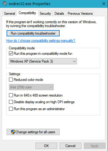
Unfortunately Windows 10 sound recorder does not support the
wav file format, but you can use the program sndrec32.exe
from Windows XP. Copy the executable from the directory
C:\WINDOWS\system32 of Windows XP
or get it from the Internet for instance here
http://disk919.com/tmp/sndrec32-winxp/READ_ME.html. Copy it
into a suitable directory on Windows 10 and set the compatibility mode as
follows:
For CW memory programing there are following symbols :
$O - own callsign
$C – callsign of the current QSO
$L - own locator
$R -
RST of the current QSO
$Q -
RST with short nines
$P - RST played at double speed
$N - contest number of the current QSO
$M - contest number with short
leading zeros
$K - contest number with zeros as the
letter O
$<1-8> – memory content under the keys F1-F8
In addition to the
standard CW characters there are also following composite characters:
+ - AR
\ - correction
) - BK
( - KN
% - AS
* - SK
When programing the CW memories you have to pay attention not to create a
loop by putting a memory symbol ($<number>) into the same memory or indirectly through another
memory. The program would work, but after stack exhausting the keying would be
automatically stopped. For every memory a button label can also be
set to identify the
assigned memories.
The CW keying is possible only in the CW mode. The speed can be changed from 6 WPM to 60 WPM by using the slide bar in the "CW/SSB/Recorder
control" window or the shortcuts ALT/-
and ALT/=. The keying can be done either with the paddle
or directly from the
keyboard in the window "CW/SSB/Recorder control". You can enter all
symbol variables and shortcuts (F1-F8), too. You can enter the characters in advance.
The characters which have not been sent yet can be deleted with
the <Backspace> key.
The following shortcuts can be
used:
F1-F8 - send memory
ALT/F1-F8 send
CW/SSB memory in the loop according to the parameters set in the "CW/SSB/Recorder
control" (see below).
ALT/= - increase the speed by 1 WPM
ALT/- - decrease the speed by 1 WPM
ESC – interrupt
(only in the main
log window)
ALT/N – direct CW input from the keyboard
The predefined memories can be
sent repeatedly by multiple hitting the relevant key (F1-F8).
The CW or SSB memory can also be sent in the loop
with pause for RX. Set the parameters in
the "CW/SSB/Recorder Control" window,
the
memory to repeat, the time gap to RX and
click on
"Start" or use the shortcut keys
ALT/F1-F8. Clicking on the button
"Stop" in the window "CW/SSB/Recorder control", hitting ESC
in the main log window or touching the paddle terminates the keying
at any time.
If you use the PC sound card as the modulation source the headphone output
is the best choice. You have to set the optimal modulation
level by the volume control in Windows or
with a resistor trimmer. Of course a shielded cable is
necessary for the audio connection. It is also
recommended to use a
small audio transformer to
galvanically separate the PC and TRX grounds. On
the modern TRXs with the internal USB sound card it's always better to use
this but keep in mind that it must be connected and available in Windows
before starting VUSC.
You can also switch
on the CW monitor by checking "CW/SSB/Cluster/Chat->CW
monitor". However, the monitoring may not be quite accurate on some sound
chips due to their high latency. Normally it's better to leave it off and
use the monitor in the TRX.
11. Network operation
The network enables the communication of connected computers, sending QSOs, skeds,
synchronization, sending messages, packet sharing etc. A connected computer is called
network node.
After opening a contest a node can (but does not need to) be logged on (assigned to) one
or more bands. The band(s) for a particular node can be entered by "Network->Own
band". The network is then automatically enabled for this node and the skeds
scheduled on other bands and messages can be sent to this node (see below). The assignment
of bands to nodes is displayed in the window "Nodes". Only one node can be
logged on a specific band, but one node can be logged on more bands. The assignment is
valid until a new node logs on the same band. For logged on nodes their IP addresses are
displayed. The bands which are not assigned to a node are marked with
IP address 0.0.0.0. Automatic
network search for on-line nodes is performed when the program is started or a new band is
assigned. The same check is made always when the node list is refreshed by clicking the
button "Network ping". "A" (active) next to the IP address
and IP in blue means an
on-line node, "O" (own) means own band,
no mark and red IP address means lost connection. The program
also automatically checks the
network connections every 20 seconds and updates their status (network heartbeat).
The network is in "disabled" state after
the program start. It means just limited network functions are enabled.
This prevents receiving QSOs from other nodes
and all log related operations before a contest file is open
while the contest is already running on the other nodes. Such situation may
occur for example when a node has
been connected later during the contest, the node had to be restarted etc. The
full network functionality is enabled by unchecking the "Network->Disable"
menu item or logging
(assigning) the node on a band.
Do it only if
a contest is open
on the local node and synchronization (see below) has been made.
Failure to do so may lead to data lost or damage. For security reasons the contest file name
must be identical on all nodes in order to avoid operator mistake and overwriting the
contest log by the data from another contest.
When the network is enabled a new or changed QSO on any node is sent automatically to all other nodes in the network
after
entering/confirming it by RETURN
key no matter if the node
is logged on a band or not.
Receiving QSOs from other nodes can be stopped at any time
by checking the menu item "Network->Disable".
The network is back in the "disabled" state then.
If a node is logged on a band skeds can be sent to this node on this band from another node (band)
by using "Sked-><band>" in the menu or with the shortcut ALT/E or using CTRL/ENTER
when confirming a complete QSO.
They are
displayed in the "To Do" window. By double clicking on an item in the "To
Do" list the QSO is copied into the current line in the log. The skeds which could
not be made can be deleted from the "To Do" window by
selecting and pressing
the DEL key. For relaying information among the
bands a text message can be sent either to a specific node or to all nodes
in the network by using ALT/L or by clicking in the input box of
the window "Network Message". Only nodes logged on a band can be chosen as a
specific message target.
If any information from other nodes
gets lost during the operation (for example computer crash,
network connection interrupt, later connection to the network etc.) you can synchronize
the local log with a log on another node using "Network->Band to
synchronize". At first the system time and zone setting is transferred. Then you can
choose either the transfer of the complete log from the node or just the selected band. A
message with the number of QSOs to transfer is displayed at the transfer beginning and the
message "Synchronization complete, nnn QSOs transferred" indicates the
successful completion. Use the synchronization also when an inconsistence in QSO numbering
on the network is detected. If any problem occurs during the synchronization, the
synchronization is automatically interrupted after 5 second time out. The broken
synchronization can also be reset by disabling and re-enabling the network
("Network->Disable").
The program also
detects inconsistencies and differences in the contest numbers. If the
difference is not too big that synchronization would impact the source node
operation it is performed automatically.
CAUTION! All QSOs with the same number on the same band on the local node
are overwritten by the data from the network node.
If a new QSO is inserted/changed from a node which is not logged on the
relevant band a confirmation is required, because it can cause double numbering on this
band. The same confirmation is needed if a band should be taken
over by another node. When running secondary nodes (for example a second search and pound working place in the
VHF contest) on one band use the button "Book #" for requesting a contest number
from the node which is logged on the relevant band in order to avoid QSO
double numbering.
The number is booked with regard to the current state at the primary (usually run) node.
If the operator at the primary node entered a call and moved
the cursor to the next input field, the QSO number
is
blocked for this QSO and the other operator at the
search and pound node will get the next
available number.
12. Network – installation and configuration
VUSC utilizes the TCP/IP network protocol. You have to configure
it in Windows before the operation. If there’s a DHCP server in the local network you
don’t need to do any other configuration except checking the firewall setting (see
below). If not, you have to set fix IP addresses for every node. Choose the network TCP/IP
protocol configuration of the relevant network interface in the
Windows Control
Panel and set the IP addresses. Use the address range 192.168.x.x, network mask
255.255.255.0 or any other general recommended range for local networks. Do NOT use the
automatically Windows set local IP addresses (usually from the range 162.254.x.x, mask
255.255.0.0). In Windows XP SP3, 7, 8 and
10 you can take advantage of setting the fix IP address as
an alternative TCP/IP setting so it's automatically used when no DHCP is
active in the local network. Check your setting by
the command ipconfig in the
Windows command prompt
window (cmd) and also check the connection between the nodes with the ping command. CAUTION!
If you’re using firewall on the individual nodes, make sure that the VUSC
port number (default 5068) is enabled for TCP and UDP
packets in both directions for VUSC
application
and also broadcast
packets are allowed. Free versions
of some firewall software (for
example Sygate Personal Firewall) don’t support allowing broadcast packets for a
single application. In this case it’s better to switch
off the firewall. If this is
not possible for security reasons
use the option "No broadcast"
in "Network->Setting" on
ALL nodes (see below),
but it means more work with the network setting.
If there are more network interfaces
installed on your PC (Ethernet card, WiFi, modem
etc.) VUSC picks up the first suitable interface. You
can change it in the network configuration
of VUSC ("Network->Setting"). The network is re-initialized in this case,
i.e. the network is disabled and you have to log the node on the relevant band(s) again. The
same applies if you change the VUSC port.
If you're changing the VUSC port choose the value greater than 1024 to avoid
conflict with other programs.
The communication with nodes connected to non-local network (for example
Internet) is possible, but you have to enter individual network addresses
and ports in the field "External address" as the broadcast packets are
transferred only in the local network. If a
node in a non-local network is behind the router define either a port trigger
(unfortunately not all routers support this option) or
a fix
port routing rule on the router
to
forward the packets for the VUSC port to the
relevant IP address where VUSC is running.
If there are more nodes behind one router you have to use different port
numbers for every node. You
also have to check the option "No broadcast" on
ALL
nodes. CAUTION!
You can assign a band only to ONE node no matter if local or external!
There are
two kind of external nodes, assigned to a band or not assigned. The assigned
ones can also be seen in the window "Nodes". Their IP address is valid until
another nodes logs on that band or is changed in the "External address"
setting. Should a band be unassigned without assigning to another
external node enter the address 0.0.0.0. External nodes not assigned to any
band can be removed from the list by selecting and clicking on "Remove".
13. TRX control
and band switch
VUSC supports control (CAT) of certain TRX types
through the serial interface. Most of the ICOM
types (with the CI-V protocol) and KENWOOD types are supported. Also Elecraft K3 is
supported as it utilizes the KENWOOD protocol. Since
almost every YAESU model has different
CAT protocol, only FT1000 family, FT847/817, FT897D/857D, FT991 and FT736R are currently supported. First you have to connect the serial ports with the proper cable (the cable type can
differ for various TRX types - straight, null modem
or USB cable in case the TRX emulates the COM port; check the TRX manual). One COM port can be used for both CAT and CW/PTT keying provided
that the TRX does not require signals RTS and DTR for communication
handshake. The paddle can't be connected to this port, though. On
some ICOM TRXs you also need to check if the item "CI-V Transceive" is
set to OFF in the setting menu and find out and eventually change the ICOM address
(CI-V Address) of the individual model (see the TRX documentation).
The CAT parameters can be set
individually for each VHF/UHF/SHF band in the menu "TRX/Band
switch->Setting" so that more TRXs can be connected to
the PC and automatically switched with the band change. One TRX can be used for
more bands (typically with more microwave transverters), but at most one TRX
can be assigned to a band. On each band you can set the TRX type, COM
port communication parameters and frequency offset to compensate possible
shift of the transverter. If the TRX type is set to NONE no CAT
communication is activated for the band. If you check the box "Change mode
on TRX" the mode change on TRX will change the mode in the log. If
there is a transverter with the IF TRX check the box "Transverter", so VUSC can "learn" the
assignment of the bands and
HF frequencies for the connected transverters (see below). If
you're using a TRX working directly on the VHF/SHF/UHF band leave the box "Transverter"
unchecked. Confirm the setting for each band by clicking on the button
"Save" and finally click on the button "OK" to write all of the settings in
the configuration file transceiver.cfg. In order to see the QRG and mode in the
window "Nodes" you have to activate the network and assign the relevant
band(s) to the PC even if the network otherwise may not be used.
To activate the CAT control choose "TRX/Band
switch->Start". It will start the TRX
communication on the current band if the TRX is defined for this band. When the current band changes the
relevant TRX (if defined) is automatically switched and activated together with the
relevant CW/PTT
and audio interfaces. After activating the operating frequency and mode are
displayed in the window "Nodes" at the relevant band(s).
This information is also sent to other
nodes on the network and displayed in the "Band map"
window as "Qwn QRG". With double click or RETURN on a spot
detail in the band map the band is automatically
changed, the relevant TRX activated if needed and the TRX is tuned to the spot QRG
and the callsign is copied in the log. To
change any setting you have to stop the CAT communication first using "TRX/Band
switch->Stop".
To ensure the right band switching and tuning of the TRX(s) when working with transverters switch
successively all relevant bands in VUSC and set manually the right band and frequency
on the TRX(s) after the first CAT activation to "teach" the
program the right assignments. VUSC stores the TRX band and frequency for each VHF/UHF/SHF band
and uses them when switching the band.
The band switch
The band switch works on the LPT or COM port
which can be set also in the menu "TRX/Band
switch->Setting". The band number is coded on the upper four data pins (6-9)
of the LPT port. On the COM
port the bands are coded as bytes starting with value 1 for 2m band, 2 for 70cm etc
sent to a controller. The COM parameters are fix: 8 bits, no parity,
one stop bit, rate 9600. The switching occurs
automatically with the band change. Unlike the rotator LPT port the band switch
LPT port can be shared with CW/PTT
keying.
14. Packet radio, DX cluster,
ON4KST chat
and posting results to SloVHF web
The packet radio operation is supported for modems as of TNC2 standard (currently TNC5+)
and for the Internet servers using telnet protocol. For the modem connection to the COM
port, use the standard null-modem cable (see the modem documentation). The communication
parameters (port, speed etc.) can be set in "CW/SSB/Cluster/Chat->Packet/Chat
Setting". The communication with the modem works only in the terminal mode
(see below).
For telnet servers on the Internet
an IP address or a server name and the port number must be set. The
most used servers with their parameters are preset in the program and can be selected from
the list. You can find other servers on the web page
http://www.iw5edi.com/ham-radio/?dx-cluster-telnet-links,65
.
The parameters are stored in the configuration files vuscwin.cfg
and quickstart.cfg. To connect to a
modem or a telnet server use the menu "Packet->Connect" in the Packet
window. To disconnect you can use either the menu
"Packet->Disconnect" or the command on the server.
If the local
network is active the computer with the TNC packet connection can work as a packet server for
those computers on the network on which the option "Packet Remote" has been
selected. Check the option "Packet->server" in the menu of the packet window.
The packet server IP address is then also displayed in the network "Nodes" window
under the name "Cluster" with T (telnet) or S (serial).
The current packet configuration is displayed in the title of the packet window.
The commands for the packet server as well as the TNC control commands
are entered in the lower line of the "Cluster/Chat" window.
The
communication with the TNC modem runs in the terminal mode. It may be
needed to set some TNC parameters (which
dedicated packet programs
mostly set automatically) manually, especially own callsign (TNC command I), modulation delay
(TNC command T), channel select (TNC command S) etc. The TNC commands
(escape sequences) are to be entered
beginning with the * (star) character. See the modem documentation for
details.
For better overview the DX spots from the packet are gathered into the "Band
map" window. Four lists are maintained for 2m, 70cm, 23cm and microwave
bands. You can select them in the menu "Band". The new spots are displayed
in blue, the spots with already worked callsigns are black. For microwave bands a bit mask in hexadecimal
format can be entered in the dialog "Options->VUSC". The mask determines the
relevant microwave bands of the current contest on which a QSO must be made for a spot to
be considered as worked. The bits correspond to the bands from the least relevant one. For
example 68 (hexadecimal) means 13cm, 6cm and 3cm bands, 78 means 13cm, 9cm, 6cm a 3cm, E8
means 23cm, 6cm, 3cm a 24GHz etc. The spot is considered to be
worked if a QSO is made
on all of the selected bands. With the "Band->Wipe" the whole map of a particular
band can be cleared. In the menu "CW/SSB/Cluster/Chat->Packet/Chat Setting"
the time
out can be set after which the items are removed from the list. If
you need complete information of a spot click on the entry in the list for
displaying of the spot detail. Double click on the detail copies the
callsign in the log.
Beside the DX cluster nodes it is also possible to connect to the ON4KST chat
using the telnet connection. You have to have an user account on ON4KST chat. Get the
user registration on the www.on4kst.com
web site. Fill
the username (usually your callsign)
in
the "CW/SSB/Cluster/Chat->Packet/Chat Setting"
and select the telnet
server info.on4kst.com. Select
"Cluster/Chat->Connect" in the
Cluster/Chat window, enter the password and the chat
number as the ON4KST server prompts.
CAUTION!
The following parameters must be set for the user on the ON4KST server to get the DX spots and messages.
/set dxclx
/set here
/set ann
/set qra <own locator>
/set na <your name>
Optionally you can filter incoming DX spots by bands by setting
/set qrg <bands> the bands can
be: 50 70 144 432 GHZ (There may be more bands
on the line separated by spaces)
For the complete list of commands and options use the command
/h
The DX cluster spots from ON4KST
work as usual and come into the relevant lists in the "Band map" window. If you
need to refresh the spot lists use the server
command "/sh dx
100".
The chat traffic is displayed in the communication window.
The chat messages are basically
displayed in black. The messages directed to you (i.e. containing your user name
in parenthesis) are red similarly as in the web chat. Other lines containing your user
name (mostly the
lines you entered) are blue.
For a direct message to a station use the command /cq <callsign>. This
command sequence is also generated if you double click on a callsign in the
chat communication window. If you hold the CTRL key, the callsign and
locator are also
copied in the log.
Beside
the DX spots the program also
gathers the callsigns and locators from the logged on users and displays
them in the the "Band map" window
(menu
"Spots->ON4KST users"). According to
the current selected band the already
worked callsigns are displayed in black, the new ones in blue. A
single click on an item in the user list displays the details.
Double click on the detail enters
the callsign and locator in the log the same way as for
a
normal
DX
spot.
Double click on the line in the list
(out of the detail)
enters /cq
with the callsign in the packet/chat
communication line
so a direct message can be typed and sent to the station.
The same with the CTRL
key does both (/cq
and log entry).
The callsigns with locators from the user list are also displayed in the
"Database
Check"
window with the special label KST instead of the number of QSOs (see
the chapter 6.). Be careful when using it,
though,
as
a
station
may be
logged on with an incorrect locator.
The
ON4KST user list is refreshed automatically every 20 minutes or
directly using the server
command "/sh us".
As there are usually many incoming lines in the packet/chat window during the contests,
is it possible to define a filter to display only selected lines. The filter supports
logical operations with individual strings. There are following operators:
~ - negation
& - logical AND
| - logical OR
[] - square brackets to build complex logical expressions (the square
brackets are used, because the normal parenthesis may appear in the ON4KST entries.)
The rules of Boolean algebra apply in the evaluation i.e. if there are no brackets the
operators are evaluated in the order: 1. negation, 2. AND, 3. OR.
Example:
You enter a string like this (without spaces): OK1DIX|[432&~DX]
The entries containing either the callsign OK1DIX or the number 432, but no DX are
displayed in the packet window.
If a
filter is defined you can switch between the filtered and unfiltered window
using the "Toggle" button. The filtered window is indicated by bright yellow
background.
The filter can be defined also for the Band map and
OK4KST users window by help of the menu "Filter->Define" in the
window "Bandmap".
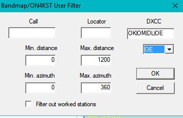
The same
Boolean logical expressions as in the "Packet/Chat" window can be used for
the fields Call, Locator and DXCC. For the field DXCC pick the standard DXCC
prefixes from the help list below. By default they are copied with the OR
operator, but the expression can be changed afterwards. To eliminate the
already worked stations check the box "Filter out worked stations". To
switch the filter on/off use the menu "Filter->Activate".
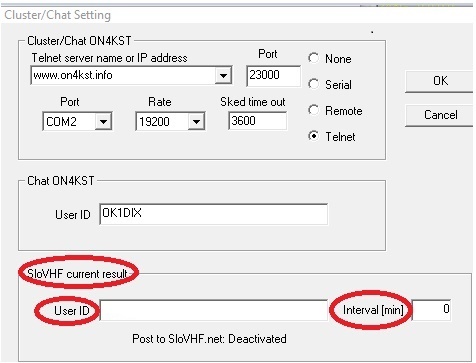
There's also an option to post your current results to
the web site www.slovhf.net.
You need to get a username on
https://slovhf.net/en/. Click on "Register" in the lower right corner
and fill out the form as required. Enter the username in the
"CW/SSB/Cluster/Chat->Setting cluster and chat" The data transfer is
activated by entering the interval value larger then 5 minutes. You can see
the status of the last data transfer here, too. The transfer is deactivated
by default when a new contest is opened/created. You can see the current
results on-line here
http://slovhf.net/en/claimed/.
Except of the
regular interval the result is also transferred when the program is ended by
"Contest->Save and Exit". If there's no point change since the
last transfer no data is transferred from the relevant band. If the VUSC network
is deactivated ("Network->Disable") data from all bands with non-zero result
are transferred. If the network is active only the data from own bands are
transferred. You can see the results at this link
http://slovhf.net/en/claimed/. They can be deleted by using your
registered username and password.
15. Communication with the program AirScout
VUSC supports communication with the Program AirScout by
DL2ALF to
employ the airplane reflection to make a QSO. The communication requires
following settings:
- AirScout
communication port (usually 9872)
-
AirScout server name (for instance AS)
The parameters must be set on both sides. In VUSC enter them in the menu
"Network->Setting". In AirScout click on the button "Options" and select the
tab "Network". It is recommended not to use more than 3 characters
for the server name. After entering the parameters activate the AirScout server by
checking the box "Activate Network Server".
To get the current list of flights suitable for a QSO a valid locator
must be entered on the current line in VUSC. Request the list of flights by choosing
"Network->AirScout request" or by using the shortcut ALT/K. The
list is displayed in the window "Current Contest Check". If the option
"Automatic request when entering locator" is checked under "Options->VUSC", the list
of flights is also
requested after hitting <SPACE> in the locator field, provided the
locator is valid. The individual entries are colored
according to their reflection potential similarly as in the AirScout plane
map. If you are logged on the ON4KST chat you can use the option "Automatic
AirScout request for KST user list". The entries in the KST user list will
then be colored according to their reflection potential. The details can be
displayed using the right mouse click and context menu on the relevant
entry. There are also options to populate the watch list in the AirScout
with the data from the KST user list if you check the box "Send watch list
from KST user list to AirScout". If you check the box "Switch display in
AirScout" the currently displayed QSO in AirScout will be switched according
to the request from VUSC.
Note that when requesting the AirScout information it can
take a couple of seconds till AirScout gathers and sends the information
back and it also will load the PC, especially the CPU. Therefore when using
the automatic data gathering for the KST user list it is recommended to
reduce the number of requests by using the filter in the band map window and
to define the distance limits in "Options->VUSC". If you don't use the
AirScout directly (i.e. you use only the server functionality) you can
reduce the system load by not starting the airplane map (green arrow) and by
deletion of the calls and locators in the AirScout input boxes.
It is
also recommended to run AirScout on a remote PC in the
local network to distribute the CPU load. In this case make sure that local firewalls are set to
allow broadcast packets for the AirScout port (usually 9872). For details see the
chapter 12 Network - installation and configuration. Especially note
that if there are more AirScout servers in the network they must have
different names and ports.
16. Sound recording
If you have troubles with receiving a DX station it may be useful to record the audio signal for
further examination. Choose the relevant signal source (microphone
or line-in) in the sound mixer recording control in
Windows. Double click or use right click on the little speaker
in the Windows task bar to get
the mixer control and go to the menu "Option->Properties->Recording" to get
the recording controls. Set the
appropriate signal level so the recorded signal is not distorted.
Use a shielded line to connect the TRX speaker with the microphone
or line in
input on your PC. A small audio
transformer for galvanic separation is recommended. If your TRX has its
own sound card or you want to use the sound chip from Microham choose the relevant
audio interfaces for input/output in the "CW/SSB/Cluster/Chat->CW/SSB Setting". (see the
chapter 10 for details).
The sound recorder controls are Record, Playback,
Back and Fast Forward. You can choose either
the button controls or shortcuts mentioned above. The usage is similar to a normal tape
recorder. The sound files
.wav are stored in the contest directory
in the subdirectory sound. Their name
consists of time stamps of the record start and end, record hour and minute and the callsign. The hour, minute and callsign is taken at the end of the recording
from the current line in the log. Beside the
normal controls confirming a QSO with <Enter> terminates
the
recording. If the box "Permanent recording" is checked in the "CW/SSB/Recorder
control" window a new sound file is automatically started and the
recording continues.
When the recording is running the seconds are counted in
the main window. One minute represents about 1MB of the disk space. The
files have the standard WAV format
and can be played by any Windows player and/or
be further processed. Be careful when
using the recorder in order not to overfill your hard disk with the sound files.
17. Rotator
The hardware
The rotator control is possible through COM (also virtual), LPT
or USB port. The COM
port control supports Yaesu and SPID rotator standards (for more information see the
relevant Yaesu/SPID documentation).
You may
experience some delay in the rotator position display when using the
older
SPID rotator controller.
It's not an error, it is due to
its low communication speed
which cannot be changed. VUSC supports up
to 10 rotators simultaneously. The maximum number can be set in
"Options->VUSC".
The rotators connected through LPT or USB port are using a special
VUSC protocol. They require a simple adapter either with the PIC
or Arduino microcomputer (see below), but the VUSC
protocol provides more
features compared to standard protocols. The adapter schemes are in the
Appendix. There are two options for the USB connection. The older one with the PIC
CY7C63001AFWP1 and newer one with Arduino UNO R3. Both have pros and
cons. The adapter with the PIC has a bit less accuracy and works only on
32bit Windows (the PIC manufacturer does not deliver the driver for 64bit
Windows), but you don't need to upload the firmware and the installation is
simpler. The new adapter with Arduino works on all Windows and it's
smaller, but the software installation is more complex as you have to upload the
firmware.
There are PCB boards for all types of adapters. The PCB data are available in the files
vusc_generic_new.brd
and
vusc_arduino.brd
in Eagle format.
The PCBs are double sided and silkscreened
so the corresponding scheme can easily be identified.
A potentiometer or another sensor which delivers linearly
proportional voltage theoretically from 0 to 5V (practically about 0.1 to
4.9V) as position indicator is a general prerequisite for the USB or LPT
adapter.
The potentiometer value can be from about 200 ohms to about 30 kOhms. The higher
potentiometer value increases the risk of inducing of interference voltage in the
connection wires when transmitting. The potentiometer can be fed
either from a voltage or current source. The voltage source requires 3 wires
for connection, but it works with all potentiometers independently of their value. The current source needs only 2 wires, but it must be adjusted to
the individual potentiometer value. The output of the external sensor is to be connected
between the point C and the ground (see the scheme).
The adapter for LPT and PIC is designed with
the 8-bit
ADC0804LCN
converter which has sufficient precision for
usual
contest antennas. Normally 8-bit digital information comes to the LPT data signals D0 to D7 (pins 2-9), but the program is able to evaluate also
9th bit on the ACK signal (pin 10). You can use
your own A/D converter with
more bits for higher
precision if you change
the circuit accordingly. The adapter
with Arduino utilizes its internal 10-bit A/D converter so the
ADC0804LCN is not used (see the scheme).
The maximum
input voltage
must not exceed 5V in any case,
because it may destroy the A/D converter.
Therefore there is a protection circuit with LM393N in the adapter.
There are DIP switches on the board to select the voltage or current source
and the relevant protection. The following table shows their setting for each
case.
| Position sensor |
DIP1 switch 1 |
DIP1 switch 2 |
DIP2 switch 1 |
DIP2 switch 2 |
| Potentiometer
(voltage) |
OFF |
OFF |
OFF |
ON |
| Potentiometer
(current) |
ON |
ON |
ON |
OFF |
| External sensor |
ON |
OFF |
ON |
OFF |
There are also 4 jumpers for the connection of DC (for example Yaesu) or AC
(for example Kenpro) rotators. They are marked with JP1 to JP4 on the PCB. If all jumpers are installed (connected) the
DC power supply used for the adapter is also used for the rotator motor i.e.
the power supply must be sized accordingly. The motor is connected to the
pins RE1A and RE1B on the board. If all jumpers are disconnected
the motor AC voltage is to be connected to the pins AC1 and AC2 and the synchronous
capacitor to the pins RE1A and RE2B. The side motor windings are connected
to the pins RE1A and RE2B and the middle point wires (connected over the
limit switches) to the pins RE2A and RE1B. In this
case the DC power supply is used only for the adapter and can be a small one
(about 200mA).
CAUTION! Arduino
must be fed only from an external power supply 7-12V either from a 7808
regulator connected to the DC power supply (see the scheme) or a separate
small wall power supply. Do NOT use 5V from the PC USB connector as the
voltage can vary with the computer type and/or load and thus impact the
voltage reference of the Arduino internal A/D converter (i.e. the calibration
of the feedback potentiometer). Use a special USB cable with the 5V line cut
or disconnect it on the USB connector in the adapter.
Up to 3 rotator adapters can be connected to one Arduino. The red line in the scheme separates the parts of the adapter needed for
Arduino. The
following table shows the connection points marked in the scheme and on the
PCB board to Arduino pins.
Arduino pin connection table
| Point
in the scheme |
Rotator A |
Rotator B |
Rotator C |
| G |
pin A0 |
pin A1 |
pin A2 |
| P |
pin D4 |
pin D8 |
pin D10 |
| Q |
pin D5 |
pin D9 |
pin D11 |
| X |
pin D2 |
pin D6 |
pin D12 |
| Y |
pin D3 |
pin D7 |
pin D13 |
| AR |
pin 5V |
pin 5V |
pin 5V |
| GND |
pin GND |
pin GND |
pin GND |
The pins marked as DIGITAL on the Arduino board are the D pins and the pins
marked as ANALOG IN are the A pins in the table. Points P and Q for the
manual control in the scheme are connected directly to Arduino and so they are not (unlike
with the PIC adapter) on the adapter board.
Old USB adapter with PIC - installation and calibration
The programmed PIC circuit CY7C63001C-PXC (order Nr. CY7C63001PFW
variant 1) is used for this adapter.
CAUTION!
The PIC
adapter works only
under 32-bit Windows as the MSUSB driver for 64-bit systems is not
available.
The PIC can be ordered together with the Windows driver MBUSB at the
company AK MODUL-BUS GmbH on the web page http://www.ak-modul-bus.de
for about 15,- euros. Unfortunately the web page is only in German, but the ordering is simple.
On the web page find the field "Suchbegriffe" (Search) and type
CY7C63001C. You
will see a couple of links, choose "Mikrocontroller CY7C63001C-PXC mit
Firmware". On the next page check under the title
"Bestellen" (Order) if
the order number is CY7C63001PFW and choose "Port-Chip Variante 1" in the field
below. Put the number of pieces into the field "Anzahl" (Number) and click on
the button "In den Warenkorb" (In the cart). This puts your order into the cart.
Click then on the icon Cart in the upper right corner and you'll get to the check out page
in English. Major credit cards as well as PayPal are accepted. Download also the latest
driver version from http://www.ak-modul-bus.de/cgi-bin/iboshop.cgi?show1200000510,254447591177330
or click on "Downloads" on the ordering page. Under the title
"Treiber für den
Mikrocontroller CYC63001 mit der Firmware Port-Chip Variante 1"
or "Port-Chip
Variante 2" click on "Details" and click
"Download starten" on
the next page. The archive zip-file contains files MBUSBprt.sys and
MBUSBprt.inf.
Extract
the zip archive into a suitable directory. You can also use the driver supplied with the VUSC
installation. On Windows XP the driver installation is
done automatically when the PIC gets connected
to the PC for the first time. Windows will find a new hardware and ask for a driver. Enter
the directory with the extracted files and finish the installation.
In Windows 7/8/10 the driver must be installed manually before connecting
the PIC to the USB port. Right click on the
file MBUSBprt.inf and choose "Install".
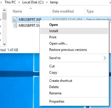
It
may take dozens of seconds till the USB communication is established when
connecting the controller for the fist time.
Otherwise the PIC behaves similarly as other USB devices (for
instance flash memory). It can be connected and disconnected at any time
while the PC is running. However, the interface must be connected before
activating the rotator
window in VUSC.
Set up procedure for one rotator:
1. Check (in case of current source feeding of the feedback potentiometer
adjust with its trimmer) the maximum voltage at
the point C (feedback potentiometer input) between 4.5 and 4.9
V.
2. Set the voltage at the point A about 0.1V lower then
the minimum voltage at the point C
using the trimmer 820R. Then set
the voltage at the point B
about 0.1V higher than 50% of the maximum
voltage at the point C
using the trimmer 3k3.
3. Start VUSC and open the setting
window by
"Rotator->Setting".
Choose the relevant rotator from the list in the upper left corner. Check
the USB checkbox.
You can also change the rotator name (the default names are Rotator0, Rotator1 etc.)
here according to your needs. Close the window by clicking OK.
4. Connect the adapter to
an USB port and activate the relevant rotator
in the menu "Rotator->Rotator-><Name>". Open again the setting window ("Rotator->Setting") and select
the relevant rotator from the list in the upper left corner. Turn the antenna to both end switch positions and check if the counter value displayed in the
"Potentiometer calibration" section is
between 258-268 and 500-510.
If not adjust finely the trimmers 820R (low value) and 3k3 (high value) in
the adapter.
5. Turn the rotator to the left end
position, enter the azimuth
value in the left field of "Range"
and confirm with "Set". Turn the rotator to the right
end position, enter the azimuth value in the right
field of "Range" and confirm with "Set". When setting the values make
sure that the indicator turns in the same direction as the rotator.
The azimuth values must be positive and not
overlapped. For example if the beginning value is 60 degrees and
the rotator turns over 380 degrees the end azimuth value will be 60+380=440 degrees
(not 80).
6. Optionally assign the rotator to the relevant band(s) in the lower part of the
setting window.
7. Check if the button controls Left/Right work properly. You can
change turning direction by checking "Motor reverse" if needed.
8. Close the setting window by
clicking OK.
CAUTION if you're using more
rotators
with the PIC USB adapter. Unlike LPT or COM ports the MBUSB
driver does not support explicit USB port numbering.
Therefore make sure that
you connect the individual
adapters to the PC and open the rotators in the
same order as they had been during the calibration so the stored
calibration values match the individual rotators. This applies for normal program start
or after PC reboot. In case of quick restart
(without reboot) it is assumed that
the rotator configuration didn't change and the program uses the last
USB port number assignment before program
termination.
The new USB adapter with Arduino - installation
and calibration
This adapter utilizes the Arduino UNO R3 with USB interface. One
Arduino can handle up to 3 rotators (see the scheme below). Arduino requires
the USB/COM port driver for firmware upload and communication with VUSC. CAUTION! Manufacturers may use
various FTDI chips as USB/COM converters so the driver installation may
differ even with the Arduino boards looking identical. The
driver mostly installs automatically on Windows Vista, 7, 8 and 10 when the board
is connected to the PC for the first time. In case the chip CH340 is used
(mostly by a Chinese manufacturer) as USB/COM interface a special driver from
http://www.wch.cn/download/CH341SER_EXE.html must be installed manually.
Also on Windows XP the driver must be installed manually (see the
description here
https://www.arduino.cc/en/Guide/UnoDriversWindowsXP). After the driver installation connect the board to the PC and find out
Arduino COM port number using right click on the "This PC" icon on the
Desktop and selecting "Device Manager". Expand the tree at "Ports (COM & LPT)"
and look for the entry
"USB-SERIAL (COMx)" where x is the Arduino COM
port number. Then upload the firmware by using the XLoader utility. First
download the utility from
http://xloader.russemotto.com or
http://www.hobbytronics.co.uk/arduino-xloader
or
https://github.com/xinabox/xLoader and install it. Start XLoader and enter
the parameters:
Arduino COM port: COMx
Baud rate:
115200
Arduino type: UNO(ATmega328)
Hex file:
vuscrot.ino.standard.hex
(i.e. the firmware file
from the VUSC directory)
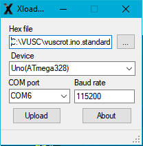
Set up procedure for one Arduino adapter:
1. Check
or adjust
with the trimmer of the current source if
it's used for the feeding of the feedback potentiometer the maximum voltage at
the point C (feedback potentiometer input) between 4.5 and 4.9 V. Do
it for all rotators connected with the adapter.
2. Connect the adapter to the USB port, start
VUSC and open the setting
window by
"Rotator->Setting". Choose the relevant rotator
from the list in the upper left corner. Check the USBCOM
checkbox and the rotator identification A, B or C according to the pins
to which the rotator is connected (see the table above).
Set the Arduino COM port and Rate 38400 and confirm both with
"Set". You can
optionally change the rotator name (default Rotator0, Rotator1 etc.)
in the upper right corner according to your needs.
Repeat this step for all rotators connected with the Arduino
adapter and close the window by clicking OK.
3. Connect the adapter to the USB port
(if it's not already connected) and activate the relevant rotator(s)
in the menu "Rotator->Rotator-><Name>". Open again the setting window ("Rotator->Setting") and select
the relevant rotator from the list in the upper left corner. Turn the antenna to both end switch positions and check if the
minimum counter value displayed in the
"Potentiometer calibration" section is
less than 200 and
the maximum value is in the range from 950 to 1020.
If the feedback potentiometer is fed from the voltage source the maximum
value is guaranteed automatically. In case of current source
adjust
the maximum value with its trimmer
(see the scheme) if needed. If the minimum value is higher than 200
you may think about mechanical shifting the feedback potentiometer gear
in the rotator.
4. Turn the rotator to the left end
position, enter the azimuth
value in the left field of "Range"
and confirm with "Set". Turn the rotator to the right
end position, enter the azimuth value in the right
field of "Range" and confirm with "Set". When setting the values make
sure that the indicator turns in the same direction as the rotator.
The azimuth values must be positive and not
overlapped. For example if the beginning value is 60 degrees and
the rotator turns over 380 degrees the end azimuth value will be 60+380=440 degrees
(not 80).
5. Optionally assign the rotator to the relevant band(s) in the lower part of the
setting window.
6. Check if the button controls Left/Right work properly. You can
change the turning direction by checking the box "Motor reverse" if needed.
7.
Repeat the steps 3. to 6. for all rotators connected with
the Arduino adapter and close the setting window by
clicking OK.
LPT port adapter - installation and calibration
The LPT adapter requires DLPortIO driver (see the
chapter 3.) and a dedicated LPT port. Note that
it works
only on 32bit Windows. Otherwise the procedure is identical with the
installation of the PIC USB interface with these changes:
- Skip the part describing PIC and its driver installation.
- Point 3. Make sure that neither USB nor USBCOM checkboxes are
checked. Then select the LPT port from the port list and confirm with "Set".
- Point 4. If you use your own A/D converter with 9th bit the minimum
counter value should be between 2 and 12.
- On the PCB don't mount the PIC, the X-tal and the USB socket.
Connect the relevant signals directly to the LPT port according to the
scheme.
CAUTION!
Parallel port LPT may be in an
undefined state after booting the PC.
Don't switch on the motor power supply
before
activating the rotator
window to avoid unwanted switching on the motor. Also when
closing the program switch off
the motor power supply before rotator control deactivation.
Common for all adapters
After the calibration the software
end switches
are automatically set to the beginning and end azimuth values. If you have
hardware end switches in your rotator make sure that their
beginning and ending positions comply with the minimum and maximum voltage on the
potentiometer. When the setting window is open the overlap range is indicated in yellow on the
indicator edge. If the rotator turns in less then 360 degrees the
non-accessible range it is marked red. If you further need to limit the
rotating range more than the default end switches (for example due to
interference or obstacles in the range) open the setting window and set the
software end switch positions by left (lower limit) or right (upper limit)
mouse button click on the edge of the indicator. The initial (calibration)
end switch positions can't be exceeded, though. During the normal operation
the overlapping range is marked with green, but it turns yellow if the
rotator gets into that range.
If you just need to rectify the antenna direction on the already calibrated
rotator you
don't need to repeat the calibration. Aim the antenna to the known azimuth (for instance a
beacon), enter its azimuth in the field "Rectification" and click
"Set". This option works also for the rotators utilizing the Yaesu protocol. If you want to retain the setting for future
contests use "Contest->Config->Save". The rotator configuration is stored in the file rotator.cfg.
For compatibility reasons with previous versions the configuration of the
first rotator is stored also in the files vuscwin.cfg and
quickstart.cfg.
Rotator control
Rotator shortcut controls:
CTRL/< - Left
CTRL/> - Right
CTRL/space - Stop
CTRL/? – Auto (turn to the azimuth of the current
locator)
CTRL/' - cyclically switch the active rotator
The click on the edge of the position indicator turns the rotator to that
azimuth
You can control the rotators with the buttons (Left/Right/Auto/Stop) in the
relevant indicator window or with the manual switches connected to
the adapter. The keyboard shortcuts work for the active
rotator i.e. the one with the red arrow (the others are blue). The active rotator is switched
either according to the band assignment or explicitly by using CTRL/'.
18. Appendix - schemes and pin-outs of the interfaces
and adapters
Use only shielded
cables for all connections between the computer and TRX. The shield should be connected to
the signal ground (GND). The 100 Ohm resistor in the collector of the keying transistor is
only for the protection. It can be leaved out if necessary.
Arduino adapter bottom side (view from the top side)
Arduino adapter top side
Arduino pin connection table
| Point
in the scheme |
Rotator A |
Rotator B |
Rotator C |
| G |
pin A0 |
pin A1 |
pin A2 |
| P |
pin D4 |
pin D8 |
pin D10 |
| Q |
pin D5 |
pin D9 |
pin D11 |
| X |
pin D2 |
pin D6 |
pin D12 |
| Y |
pin D3 |
pin D7 |
pin D13 |
| AR |
pin 5V |
pin 5V |
pin 5V |
| GND |
pin GND |
pin GND |
pin GND |
The pins marked as DIGITAL on the Arduino board are the D pins and the pins
marked as ANALOG IN are the A pins in the table. Points P and Q for the
manual control in the scheme are connected directly to Arduino and so they are not (unlike
with the PIC adapter) on the adapter board.
PIC/LPT adapter bottom side(view from the top side)
PIC/LPT adapter top side
For the usage with the LPT port don't
mount the PIC, the X-tal and the USB socket.
Connect the relevant signals directly to the LPT port according to the
scheme.
|