|
The first Amateur Lunar tests & contacts |2nd part: 1966-1976 On line translation needed? (for 1st part [1953-1965] click here)
144 Mc and Up Out in California one of the old timers of v.h.f. has come forth with the word that he soon hopes for success with moonbounce gear for 1296 and 432 Mc. John, W6NLZ, sez that although his 15-foot dish is a bit small he expects good results as the gear gets whipped into shape. Tests from KP4BPZ caught John with troubles of all kinds hut he did hear them and sez their activities are a big inspiration. “The only thing missing on 1296 now is a new converter hut I have made up a bread hoard which will soon be repacked to fit the rack. Would like to stress the regular schedule business on two and six meters. They don’t set records hut they do provide a platform of activity around which the newcomers can gather. A real good example is two meters. Each Sunday morning at 8:00 AM. I work K7TCW. Now and then we can’t make it but most of the time we can.” You sure have something there, John. We’ve noticed from Al’s reports that your contacts are more or less a sure-fire thing these days. John is also active on 220 Mc. and is always looking for new contacts on that band. In Los Angeles WB6IOM writes that he is continuing work on a 7650 amplifier for 1296 Moonbounce. He sea he is getting about 200 watts out but he can’t understand what happened to the other 200 watts. The tube is supposed to put out 400 watts and although everything looks good the tube just won't deliver more than 200. Any suggestions anyone? Skeds are continuing with W6RPH (80 miles) on 1296 and signals are about 20 to 40 dB over the noise across this path. 1296 Mc activity is growing in Florida, too. Jim Hagan, WA4GHK tells us that he and Jack, K4NTD hope to he making two-way contacts before you read this. One-way transmissions over the 75-mile path have been consistently good. Others in Florida preparing for 1296 Mc work are WA4BYR, W4VWH, W4NKN and K4IXC. Jim also reports that 220 Mc seems about dead in his area but he’s still interested and would like to keep skeds on any bands between 1296 and 144 Mc. At Bryn Mawr, Pennsylvania, K3ADS has been busy with antennas. He has recently erected a new 16-element 432-Mc colinear for TV and a 32-element colinear for 1296 Mc at 80 feet. K3KFL has also installed a 32-element colinear for 432-Mc T.V. The word from Connecticut is that Ed, W1HDQ, is on 432 Mc every night that he is at home (Canton) from 9:00 to 10:00 P.M. EST and longer if conditions warrant. Ed recently built a new two-stage transistor preamp for 432 Mc and says it’s working very well. From Newington WA2BAH/1 writes that his present standing on 220 Mc is six states in three call areas and about 200 miles. Stan tells us that during the September contest he operated in Maine with W1UGQ and they worked 30 stations on 220 Mc, most of them on c.w. (11 sections). Rig used was a 4X150A to 11 over 11 and about 160 watts. Doug is presently using this rig with one eleven element beam in Branford, Connecticut and he’s looking for skeds on 220 Mc. Golly! New England is coming through to us this month with v.h.f. news for the column. W1OOP sea that on September 19 and 22 when he worked K2AOP and K2GRI, 432 Mc. appeared to be open a bit. On the 23rd, K2CBA and friends arrived in Hank’s front yard with a 96-element 432-Me. beam (90 inches wide by 91 inches long by 16-6 element yagis high when pointing up) on the roof of Jud’s car. On the 28th, W1OOP, W1HIV and K1IIE put the beam up on the telescoping tower on the back of the two-meter 32-element array. (Bet that is a sight to see !) W1HIV did the pole work. (That’s natural, too !) Tests showed it was 4 dB better than the 24 element Array in the clear directions. Through the top of the hill it is 6 dB better because it can be cranked up about 20 feet higher, though still in the trees. On October 17, Hank had a three-way contact on 432 Mc with K2UUR and W2MDE. On the 18th, the band was dead at 9:00 P.M. and hot at 10:00 P.M. when W1OOP worked W7PUA/2, W2BLV, K2HQL, WB2EGZ, K2DZM, W3GGR, W3CGV, W3HFY, WA2EMB, W3UJG, W3MFY, W3ZFW, K3UJD, and W3AIR. From Medfield, Massachusetts, W1HIV writes us concerning news at W1BU.“ In an effort to increase our totals on 220 and 432 Mc, we are readying the u.h.f. antennas and hope to be on nightly within the next few weeks. The weekend of October 16 and 17 we participated in K2MWA’s 432-Mc moonbounce test. On the morning of the 16th we heard and worked K2MWA. A radar signal was also heard by participating stations (very slow rep. rate). On the morning of the 17th, K2MWA was heard and worked again. Another signal was distinctly heard about 1 kc below K2MWA sending a series of dashes. No call was heard. Echoes were obtained at W1BU on both tests and could be heard in the 2.1 kc position of the 75S-1 and were positively banging through in the 50-cycle audio filter. Receiver consisted of a parametric amplifier, two-stage transistor preamp, crystal mixer, transistor preamp, 75S-1 receiver and 50-cycle audio filter.” It all sounds like you’re keeping busy, Pat, and making it pay off, too. A flurry of v.h.f. /u.h.f. activity is the way that W7PUA/2 describes the 432-Me. activity in mid October. Bob sez that at 2100 on the 18th, the is were beginning to build up and by 2130 W100P was 30 over 9 and was working 3 land. At 2220 Bob (W7PUA/2) worked W8YIO in Manchester, Michigan. On the 19th, Bob worked K2ACQ and K2LGJ. He then got on 144 Mc. and worked W8QOH in Cincinnati. Sez the fellows seemed to be working all through the south to South Carolina and southwest to Kentucky on 144 Mc. W7PUA/2 is still looking for meteor scatter skeds with stations to the west and south on 144 Mc. We are delighted to receive some news from a real old timer on the v.h.f. bands, Art Bates, W5ML. Art sez : “ Have 250B single end tripler on 432.015 Mc into a 32-element extended colinear about 55 feet up. Am rebuilding the converter for receiving right now but should be back in business come early spring.” Good to know that you’ll be back on 432 Mc, Art. The gang will be looking for those Louisiana contacts with you. 220 Me. report received from W2SEU tells us that on September 12 he worked K1UGQ/1 in Maine and on October 20 ground wave was good into Connecticut, Rhode Island and Massachusetts on 220 Mc. Exceptionally good conditions were noted on 144 Mc by a number of the 144 Mc operators during October. WB2KLD in New Jersey particularly noted October 18 when he heard a total of 13 states on 144 Mc with Ohio, Michigan and West Virginia being new ones. Tom sez he had no contacts because apparently the stations at the low end of the band were not tuning above 145 Mc. He’s also wondering whether the good conditions were in anyway connected with the comet then nearing the sun. In New York, WB2OCF notes good conditions from October 17 through 23 and lays these conditions at the door of the comet. WA2RAT sez that October 18 was “Great “ and he worked W8WEN in Ohio on phone and K8BHH and K4QIF on c.w. on 144 Mc. W2LVQ heard stations in Pennsylvania, Ohio, North and Sooth Carolina, Georgia and Tennessee on October 19 and 20. Had a contact with W4OKA in Memphis, Tennessee. (The comet was mentioned again in this report.) WA4BMC, who is a traffic enthusiast, tells us that traffic was started on 144 Mc in Miami intended for Pensacola, in other words from one end of the state to the other. The message took eight hops hot got stuck at Lutz, just north of Tampa, where it deadened from want of another relay station. The nets on 144 Mc in Florida have been working on this project for some months now and will try again in the near future. Have you fellows remembered the 41 states on 144 Mc. W8 man who recently changed QTHs? He is now K4GL, recently W8PT. Jack wants to know who needs South Carolina on 144 or 432 Mc. He’ll be back in business within a few weeks. From Louisiana, W5ML sez he has Motorola pp. 250Bs class AB1 linear. Maximum input about 480 watts on c.w. and 300 watts on A2 and A3. Art has two antennas up 60 feet, one 14-element skel. slot and the other a 16-element colinear, which he sez still beats anything else he’s ever had up. Frequency is 144.040. If anybody would like a sked in Louisiana, Art is ready and willing and his address is Box 301, Vivian, Louisiana. Interesting report from W6DNG that he and OH1NL are continuing their monthly skeds on 144 Mc and so far have heard each other in some identifiable form during each sked. He sez they need about 10 dB to make this a practical circuit and they are both working on it. Most work on both ends has been done in the receiving equipment with noise still being the barrier. WB6NFT would like to try meteor scatter work and is available for skeds with anyone above 145 Mc. Jim runs 135 watts on c.w. with an 8-element beam 60 feet up. The receiver is an HQ-110 with nuvistor converter. He’d also like some tropo skeds with southern California. K7ICW reports meteor scatter results during October produced no QSO but a non-shower test with K7ZIR in Oregon surprised him with a number of pings and short bursts on October 24. Al sez: ‘Observation of entrance of comet Imeka-esaki on October 19 and 20 into the field of the sun may have produced additional meteors to the Orionids shower. Perceptible solar noise increased one half hour before sunrise on October 19 on my sked with W0ENC on 144 Mc. We were both watching for any variation from the norm that might be caused by the comet. Wonder if anyone else noticed any abnormalities?” (You may have noticed remarks earlier in the column regarding the comet, Al.) News from Nevada sea that K7WPQ, W7AKE and K7ALG are operating on the 146.94 Mc f.m. frequency in Las Vegas. K7RKH is working K6TSK in southern California on two-meter s.s.b. Two reports from Harrisonville, Missouri. K0IFPC reports working W5SWV in Denison, Texas on October 10 and K0JWN notes that two meters was pretty good during October with good groundwave on a number of occasions and increased activity.
V.H.F. DX The moonbounce bug has bitten VE2LI deeply and has led him into making the decision of doubling the size of his 96-element array to 192 elements. He may even go further than that and come up with 256 elements! This on 420 Mc. However, George is also interested in 1296-Mc moonbounce work and wonders who is working on the same project and how good the chances are of contact. He hopes to have 50-watts output and a 4-foot dish on 1296. Sez George: “On tropo things have been the usual quiet band with only W1QWJ heard fairly regularly. Occasionally, bursts are heard from W2MDE and a short burst was heard from W2CCY. It seems that 250 miles over a reasonable path is not too difficult hut 350 miles has to have the help of a good opening. It will be interesting when we once again get aurora to check if this can be used at 432 Mc I know of nobody that has tried it.” Sounds like George is still all by himself on 432 Mc. in the Montreal area but as any good vhf, man is not easily discouraged. Good luck George! From Ontario, Canada, VE3DSE sez that conditions in his area (Toronto) on 144 Mc have been quite good since about mid July. On July 13, he worked W2AZL W2AMJ and W2QHZ with good reports. On the 28th he worked W8DDO in Michigan. The best dates in August were August 9, 11, 13 and 14. On the 14th, Gus worked W3BDP in Delaware for the fifth new state since mid-July. September 6 brought contacts with WA9KRT in Indiana and W9AAG in Illinois plus VE2WT in Montreal who runs 35 watts to a single S-element beam. VE3DSE now has a total of 12 states in seven call areas running 25 watts. “Antenna system is 32 elements 50 feet up and fed with Heliax. Receiving with homebrew 417A converter and 75A2. Operate mostly c.w. on 144.030 with some phone on 144.105. Rave had no luck at all toward W1 land and would like some of the boys there to keep an ear open. Now building 829B for about 100-watts input and by end of the year will have a pair of 4CS250Bs on the air running the now legal 1 kW in Canada. Also working on 432-Mc converter and transmitter. Transmitter will have 5894 pushing a pair of 4CS250Bs to legal limit on c.w. and antenna for the present is a 21-element yagi fed with half-inch Alucell.” Sounds as if VE3 land is really serious about the whole thing, too! Glad to hear it and hope to work you from KP4 land on 144 Mc. QST January 1966 The World Above 50Mc - CONDUCTED BY SAM HARRIS, W1FZJ
Once upon a time it was enough to know that your receiving set up had a sensitivity of 1 microvolt for some specified signal to noise level at the speaker. This method of receiver rating was (and still is ) fine for the low frequencies where the antenna temperature is always high compared to the receiver. As a result of the post-war stampede to the v.h.f. however, the need for a better method of comparing receiving equipment became apparent. After some fumbling around the communications people settled on “noise figure” for comparing the relative weak-signal merits of receiving systems. This method is fairly easy to use and yields a number which is not dependent on receiver bandwidth, gain, etc. It was (and still is) an excellent method, but it bases its measurement on a comparison with a perfect receiver. As long as your receiver is poor the comparison yields nice numbers which, when properly used, allow you to calculate how strong a signal must be to be detected by your receiver. The more perfect your receiver, the less meaningful the rating system becomes. If, for instance, your 420 Mc converter has a 6 dB noise figure, you might be inclined to think that the most improvement you could realize with perfect receiver would be 6 db. This, however, is not the ease. The amount of improvement you can obtain cannot be determined by measuring your receiver as a separate entity. It is also necessary to know what your antenna is doing. Not in terms of gain; in terms of temperature. Now, pay attention, especially if, in the past when antenna temperature was mentioned, you turned to the advertising section so you wouldn’t have to think a little. It just so happens that receiver temperature and receiver noise figure are the same thing. As a matter of fact you don’t measure the noise figure at all ; you measure the equivalent temperature of your receiver and calculate the noise figure from that. Back in the days when noise figure was the ‘‘in‘‘ way to do it, you terminated the input of your super-special converter with a resistance which properly matched (you hoped) its input impedance. This resistor, usually 50 ohms, was at room temperature. The noise output of your receiving system was then read on a meter. If the converter was perfect, all the noise at the output would be coming from the resistor. How does the resistor make “noise? “ The same way a vacuum tube does. Random-electron motion generates noise. The amount of random-electron noise varies with temperature. Vacuum tubes have hot cathodes and make lots of noise. Resistors at room temperature are relatively cool and make small amounts of noise. But they do make noise and they make it at all frequencies. Now the feedline from your antenna looks like 50 ohms too, assuming a 50 ohm feedline matched to your antenna in some reasonable manner. So if you switch from the 50 ohm resistor at room temperature to your feedline, what will you see at the output of your perfect receiver? No! No! The noise doesn’t go up! That was back on 20 meters. This is 420 Mc, remember? Remember all those charts; about antenna temperature vs. frequency and sky temperature behind the moon, that you skipped over the last year or so? Well, if you dig them up you will note that even with your antenna aimed at the horizon its temperature will only be 150 degrees or so. Degrees Kelvin, that is. Temperature is temperature, regardless of the name you give it. It just so happens (thanks to Lord Kelvin’s erudition and foresight) that the Kelvin scale is handier to use in this case than Fahrenheit or Centigrade. The accepted value for room temperature is 293 degrees Kelvin, so the resistor you have on your converter at room temperature is roughly twice as hot as your antenna. How can your antenna be “colder” than your resistor when they are both at the same air temperature? (I live in Puerto Rico where this situation always obtains.) If yon think about it you will recall that your antenna is not a resistor and in particular it surely isn’t a 50 ohm resistor. In fact, it had better be something less than an ohm if it is going to be an antenna. It looks like a 50 ohm impedance because of the various and sundry currents induced in it by sources at or near its resonant frequency. The temperatures of these sources are what determines its temperature. If you aim the antenna at the horizon, half of its beam will illuminate the earth which is around 300 degrees, and the other half of the beam will be looking at the sky, which might be anything from 3 or 4 degrees to 50 or so. Now if half of the antenna pattern “sees” the earth, you will have 150 degrees plus whatever the sky contribution is. If you tilt the array up a few degrees, so that the first null is just below the horizon, you can lower its temperature to just a bit more than that of the sky. In this case the noise output of your perfect receiver would drop like a stone when you switched to your antenna. Of course this is all academic if you have a receiving system with a 6 dB noise figure. If your receiver thinks it has a 1000 degree or so resistor across its input terminals, it will be pretty complacent about things you do in the way of antennas. Remember, the important thing about temperatures is that they always add. If your receiver looks like 1000 degrees and you switch from your 290 degree resistor to your 100 degree antenna the system temperature will change from 1290 degrees to 1100 degrees. That’s a big change to a radio astronomer but you are going to have a hard time telling the difference on your communications system. QST March 1966 The World Above 50Mc - CONDUCTED BY SAM HARRIS, W1FZJ More Noise about Noise
QST April 1966
VK3ATN informed us that he hears his own
reflection of signals from the Moon. He uses the devices available to
amateur on 144 MHz band. The idea is based on rhombic antenna, pointed to
the calculated place in an area where is Moon for about hour three to
five times per a month. Power was 150 W and converter with 6CW4. He
recorded his own reflections, which were up to 20 dB above the noise! If
someone should attempt to these serious interest, pse submit more
information at OK1DE.
QST June 1966 Moonbounce Down Under
For the past few years moonbounce activity has been reported in terms of U.S.A. to Europe or U.S.A. to U.S.A. Rumors of activity in Australia and New Zealand have come and gone with no actual results reported. In early 1965 VK3ATN of Birchip, Australia, started planning to enter the moonbounce ranks. After many long talks via h.f. radio (mostly 40 meter s.s.b.) with W6YK, K6MYC, W3SDZ, W1FZJ and others, the decision was to try it first on 144 Mc. The prime reason for choosing 144 Mc was the availability of equipment plus good salesmanship on the part of Bill, W6YK. The fact that there are many more stations equipped and ready to go on the 420 Mc band is offset by the lack of ready communication with these stations. The h.f. bands are the only practical way to exchange ideas and discuss the problems encountered in setting up for a moonbounce test half way around the world. Ray, VK3ATN, is well set up with rhombics, beams and verticals for all bands. Not only does he place high (like on top) in the VK v.h.f. contests, he does the same in the h.f. world-wide contests as well. He handled the VK end of the first VK/W1 160 meter s.s.b. contact with W1BU for instance. Knowing his past performance record it was only natural to expect results from him on his moonbounce efforts. Ray is located in south-eastern Australia about 180 miles northwest of Melbourne. The land around Birchip is flat and ideally suited for the use of ground-mounted beams. The results obtained and the techniques employed by the first amateur moonbouncers, W3GKP and W4AO, impressed Ray. The extreme distance involved in working continental U.S.A. only allows a couple of hours of common moon at best. The final decision was to aim at a points in space which is visible to stateside stations and in the path of the moon at least three or four days a month. This allows the use of large, fixed arrays and eliminates the problems encountered in tracking. It does not, of course, eliminate the problem of finding the moon; but once you have the beam properly oriented you can relax. The moon will definitely come back at the appointed time. The aerial chosen for use in the Birchip efforts consists of four rhombics with 342 feet on each leg. The individual beams are stacked roughly one wavelength apart with a mean height of 24.4 feet. Apex angle for 144.090 Mc is 11 degrees 28 minutes. Calculated gain is approximately 34 dB with a main-lobe radiation angle of 4 degrees. This is approximately the performance one might expect from a 150 foot diameter parabolic reflector. The half-power beamwidth is 3.5 degrees which allows about 8 to 10 minutes of moon time at full gain. (Minus 1 dB points.) Ray had the aerial up and working for his first schedule on March 1, 1966. Skeds were held with W6YK and K6MYC on March 1, 2, 3, 4, and 5, 1966. For a first try results were terrific! Signals from K6MYC were heard during the March 5 schedule period. They were pretty spotty and no complete calls were copied but complete letters, some in sequence, were received at bot.h ends of the circuit.
The path was open? A little refinement on both ends should make a two-way contact a reality. Unfortunately the 60-foot parabolic reflector at S.R.I. which was used by K6MYC was no longer available. A new site and a new antenna had to be found. As of the middle of May the site has been located and the antenna is under construction. Target date for Mike, K6MYC, is May 25. Next schedules were with W6YK on March 28, 29, 30 and 31. The rhombic had been completed and tuning of both the beam and the equipment resulted in the first recorded echoes by Ray of his own signals on the 28th. The equipment at VK3ATN consists of a 4X150 final driven by a heterodyne mixer out of a 32S1. Power input is 150 watts. The receiver on this schedule was a 5 dB converter into a 75A4 with a 500 c.p.s. filter into a 100 c.p.s. audio filter. No signals were heard from stateside but careful record keeping and fairly consistent echoes made it possible for Ray to get a “live” fix on his beam orientation and pattern. With a new Parks preamp arid a new set of coordinates to provide positive overlap on all possible moon times Ray went into his third schedule loaded for bear and primed to hear and record his own echoes. Which he did. Not only did he hear them but he predicted where in advance. Echoes on this schedule were running 15 dB or better over the noise. Complete returns were copied again and again for the full ten minute period. Let no one be deceived! VK3ATN is ready for a 144 Mc moonbounce contact! Anyone who can hear his own echoes with not more than 700 watts into the antenna can work him. As a matter of fact if K6MYC has had any luck in getting his new antenna up and running he has probably already worked him. Late news about the schedule can be heard on 7090 kc at 0800 GMT Mondays and Thursdays. 0230 GMT on 21,415 kc Saturdays. 144 Mc schedule times for the summer months are as follows: June July August September
Date GMT Date GMT Date GMT Date GMT
-------- -------- -------- --------
17 2116 15 2003 11 1744 7 1531
18 2223 16 2108 12 1849 8 1634
19 2323 17 2205 13 1949 9 1735
21 0016 18 2305 14 2043 10 1830
11 1848
Ray transmits odd two-minute intervals starting ten minutes before and continuing twenty minutes after the times noted. He listens in the even two-minute periods. (Odd and even counted from the beginning of each hour.) All times and dates are GMT. Frequency of transmitter is 144.090 Mc. Receiver tuning range plus/minus 5 kc, maximum. QST July 1966 One-Way California - Australia on 144 Mc
On July 18 at 2259 the first copyable signals from K6MYC via 144 Mc moonbounce were received by VK3ATN at Birchip, Australia. On each succeeding listening period until 2320, Ray was able to COPY complete sequences of Mike’s transmission. By “copy” we mean to hear and understand by ear the intelligence transmitted by another station. No trick gadgets or integrating pen recorders were necessary. The tape recorded signals when played back later on 7.090 Mc s.s.b. were easily copied. In fact, instead of answering the “how did you make out?” question, Ray played a section of the tape and let us decide for ourselves. We had no trouble in identifying K6MYC’s complete calling sequence despite the trip to Australia via the moon and back to Puerto Rico via 40 meters. Unfortunately, frustrating noise problems plagued the entire July schedule period. Fortunately, Ray was able to eliminate his interference by using an i.f.-noise blanker. (Described by W7UAB in the November 1965 VHFer.) Mike was not able to clear his problem in time to make the effort pay off with a two-way contact. About one more schedule should do it. Congratulations are in order for the operators on both ends of the circuit and good luck wishes for future skeds! Keep tuned to 7.090 Mc at 0800 GMT Mondays and and for the latest news. QST September 1966 VK3ATN - K6MYC Moonbounce Ray VK3ATN, reports the August moon- bounce skeds with K6MYC were almost a duplicate of the July efforts. Signals from K6MYC were slightly down on the average although the peaks were somewhat higher. No reception by K6MYC so far. In an effort to facilitate finding his signals, VK3ATN will in the future answer on the frequency where he hears signals. For example, if (when) he hears K6MYC he will zero beat the frequency he is receiving the signals on. This will, of course, be Mike’s original frequency plus the doppler shift. (With the moon rising and only 4 degrees above the horizon, the doppler shift would be around 400 cycles at VK3ATN’s end of the path.) VK3ATN’s signals as received by K6MYC will be coming from a “leaving” moon and will be shifted down in frequency. This narrows the searching area down to less than a 200 cycle slice just above the original transmitting frequency, which is available for calibration purposes. Hopefully this technique will produce results during the September 7 to 11 schedules and future tests. QST October 1966 Moonbounce Schedules Continued VK3ATN and K6MYC had bad luck on the September schedules. Ray modified his rhombic in an effort to prove his calculations. He proved them but lost enough gain in the process so that his own echoes were barely detectable. Mike lost power in his transmitter and was only able to run something less than 150 watts. W1BU lost their preamplifier just before sked time and only discovered it when they were unable to hear themselves. K1KKP had a malfunction in his 60 foot helix system and heard nothing but shot noise. November and December sked times are listed below. November December Date Time (GMT) Date Time (GMT) 1 1223 2 1407 5 1611 25 0805 28 1017 29 1157 QST November 1966 Australia to New Jersey on 144 Mc Things that happen late in the month may end up as QST “ Strays,” regardless of their historical significance. This happened to the VK3ATN - K2MWA/2 144 Mc moonbounce QSO of November 28, 1966. You may have missed the paragraph in January QST, or the bulletin on W1AW, so here is the full story. Ray Naughton, VK3ATN, Birchipp, Australia, has been working on his 144 Mc moonbounce project since early 1965. His equipment and 4 stack rhombic were described in this space in July, 1966, QST, p. 84. He has received his own echoes with good strength on numerous occasions, and has copied K6MYC well. But with the 150 watt VK power limit, getting through to U.S. stations would take some doing. The trick was finally turned by the Crawford Hill V.H.F. Club, Colts Neck, N.J. Using a 60 foot commercial-experimental dish, K2MWA/2 maintained communication with VK3ATN for six minutes, beginning at 1010 GMT, November 28. Signals from VK3ATN were just about at the noise level, in a 300 cycle bandwidth. Running a kilowatt input to a 6183 amplifier, K2MWA/2 had 650 watts going into 1 5/8 inch coax, feeding the 60 foot dish, and their signal peaked at 18 dB over the noise at VK3ATN. They were audible for three minutes before and after the 6 minute period of reception at K2MWA/2. The receiver at K2MWA is a 417A converter with low-noise transistor preamplifier, working into a 51J4 receiver, with 300 cycle filter. The antenna has switchable sense circularly-polarized feed. System temperature is estimated at 600° K or more. The antenna feed had somehow gotten out of alignment, and an aiming error of up to 1.5 degrees resulted. Though the dish has a 3 dB beamwidth of 9 degrees, it was found that aiming had to be very precisely controlled to receive the VK signal. Moon radar echoes on 144 Mc were first obtained at K2MWA/2 Nov. 27, and were observed again just prior to the test with VK3ATN. Signal-to-noise ratio was 1 on the best returns. New Jersey weather was dismal: heavy fog, raining and cold. VK3ATN had a clear bright sky, with the full moon seen clearly. The Crawford Hill V.H.F. Club crew are no newcomers to the moonbounce scene. Their booming signal on 432 Mc has resulted in contacts with KP4BPZ, WA6LET, W3SDZ and W1BU. On hand at the time of the VK3ATN QSO were Ed Chinnock, W2FZY, Bill Shafer, W2JIB, Dick Turrin, W2IMU, and Roger Abson. Congratulations are in order all around, for a fine effort at both ends. Next: a WAS on 144 Mc. from VK? Could take a while: Ray says: “If you think procrastination is the thief of time, you should try moonbouncing!”
K6MYC - VK3ATN QSO ON 144 MC Following nine months of partial successes, K6MYC and VK3ATN completed a two-way exchange via the moon between 1146 and 1210 GMT on December 29. K6MYC reports Ray’s signals were 3 to 6 dB above the noise and were receivable almost constantly throughout the period. VK3ATN reported K6MYC’s signals as much as 18 dB over the noise! The signals were so good that Ray was able to ask for a 7 Mc schedule following the test. The California end was 320 elements in a 70 by 25 foot colinear array fed with 500 watts out of a 32S1/HA2/3CX1000A7 transmitting chain. For receiving, a TTXMO6 transistor preamp was fed into the HA2 and then into a pair of R-390’s. Ray’s station was essentially the same 150 watts used in the QSO with K2MWA/2 except for a slightly reduced apex angle in his 4-wire rhombic array. K6MYC says signals from the lower angle were much stronger than from the higher angle. The tests between K6MYC and VK3ATN will continue, and additional tests between F8DO and K6MYC are scheduled for February or March. W6DNG is currently testing with F8DO. K6MYC was assisted in the Australian effort by K6CLM and W6UGL. There will be a full report next month. QST February 1967 Australia to California Via The Moon
One year ago this month VK3ATN and K6MYC began a series of moonbounce tests on 144 Mc. On several occasions, success seemed close, only to elude them during some critical point in the information exchange. As reported last month, such was not the case on December 29 The two-way contact was made between 1146 and 1210 GMT; not just an exchange of reports, but a real QSO of such quality that Ray was able to request a 7 Mc sked following the test! Mike, K6MYC, tells us Ray’s signal varied from 3 to 6 dB over the noise and was almost constantly readable. In Australia, the K6MYC signal peaked about 18 db. above the noise. Mike’s big signal was launched from a 320 element collinear array built around sixteen bays of 16-element collinears with 64 directors added. The directors were mounted 8 1/2 inches in front of the driven elements. Before adding the directors, K6MYC had measured the gain of a single bay at 11.7 dB over a reference dipole; the directors added a measured 1.7 dB to each bay. Mike says he measured the entire 16-bay array at slightly more than 25 dB over the reference dipole. The array was 70 feet long and 25 feet high and was steerable in elevation from 55 to 90 degrees, and 3 degrees azimuth. The station was on a hillside at Stanford University. For transmitting, K6MYC used a Collins 32S-1 and a Hallicrafters HA-2 (a 28 Mc transverter) to drive a homebrewed 3CX1000A7 coaxial-tank final, producing 500 watts output. On the receiving side, a 52cTIXMO6 transistor preamp proceeded the HA-2 converter which uses a pair of Nuvistors. The 28 Mc signal was then fed into a pair of Collins R-390 receivers, at the operating position some distance from the array. The amplifier and converter were located near the antenna feed-point. Down under was Ray’s now well-known 150 watt 4X150, driven by a homebrew exciter. (Ray has a request on file with the Australian Government to allow him to run 1 kW d.c. input on future tests.) VK3ATN’s receiving chain is a Parks Nuvistor preamp, an Ameco Nuvistor converter and a Collins 75A-4. The secret of his signal is a stacked 4 wire rhombic, 342 feet on a leg with a maximum wire sag of 18 inches! Ray said a few months ago be thought the 11° 20' radiation angle was too high. He lowered the angle to 10° 40’ and K6MYC reported a noticeable improvement. Ray says he may lower the radiation angle another full degree. The tests between VK3ATN and K6MYC are continuing, though the 320 element array has been disassembled. Mike now has half of the array polar-mounted on the roof of his Saratoga home. In addition to testing with Ray, he has joined W6DNG in running e.m.e. tests with F8DO. W6DNG’s signals have been heard in France on F8DO’s 4 yagi array. F8DO has heard his own echoes with his homebrew Nuvistor converter and post detection system (QST, October 1965). On another moonbounce note, W6GXN has control of the SRI 150 foot dish and there may be some further tests from WA6LET this year. K6MYC says he believes anyone participating in an e.m.e. project must use h.f. for liaison schedules. (The h.f. bands are becoming more popular among v.h.f. men for liaison during other work such as meteor scatter.)
Late Item
W6DNG and F8DO made a successful two-way exchange on 144 Mc via the moon between 0600 and 0700 GMT, January 27. Bill, W6DNG, was using a 32-element expanded-extended collinear array and received F8DO’s signals as much as 12 dB over the noise. Bill has measured his antenna gain at 18.3 dB over a dipole. F8DO used an array of eight 9-element Yagis. No other information was immediately available, except that the contact was by slow speed c.w. F8DO is the second European station worked by Bill on 144 Mc. e.m.e. (earth-moon-earth). On April 11, 1964 he worked OH1NL in Finland. - W1DVE QST March 1967 VK3ATN worked K2MWA/2 on 28th November 1966 via Moon bounce. Ray, VK3ATN, had 4x rhombic antenna with an expected gain of about 30 dB, 150W of power on 144088 MHz and receiver with 6CW4, accompanied on the input with LF filter with a bandwidth of 90 Hz. K2MWA/2 had 450W RF power, the dish with a diameter of 18 meters and receiver based on transistor K5001 with KTo = 1.4. LF bandwidth was 250Hz.
Both stations listened K6MYC, who didn't work them in time because Moon is
passing the Ray's antenna for only 22 minutes. He didn't make in
also on sked on 2nd December 1966, although both stations were heard.
VK3ATN success demonstrates the possibility to make EME connections
for that ham who
has enough space for 20 and 30 meters long rhombic antenna. It confirms
the report from F8DO, who heard W6DNG (144004 MHz, the 800th vf, 4x 7.5 m
long Yagi antennas). F8DO - W6DNG QSO Via the Moon
News of the latest e.m.e. (earth-moon-earth) feat reached ARRL just before deadline for the March issue so we were not able then to give the contact the attention that it rightfully deserves. Marius Cousin, F8DO, writes that the January 27 contact was the result of more than 2 years hard work for F1BF and himself. They were also assisted by F1HR, F9FT, F9LN and others. Marius built the 72 element Yagi array and the receiving system; the transmitter was built by F1BF. Marius says the array is fed with low-loss M7A coax and is tuned to 144.000 Mc. The receiving system is a TIXMO5 preamp ahead of a Nuvistor/E88CC/6AK5/6U8 converter into a Drake R4-A receiver. He also uses a post detection system with two cross-correlated audio channels keying an audio oscillator or pen recorder. F8DO is currently conducting other tests with OH1NL and K6MYC as well as continuing the tests with Bill Conkel, W6DNG. OM Bill is no newcomer to the moonbounce game. He was the first American to work Europe on two meters when, on April 11, 1964, he made contact with OH1NL in Finland (see QST page 95, June 1964). At his Long Beach station, W6DNG uses a pair of 4X250 Bs running nearly 800 watts output. Bill’s antenna is a 32-element expanded-extended collinear of the type designed by the late Oliver Wright, W6GD, and exploited by Frank Jones, W6AJF. The gain measures 18.3 dB over a dipole. The array is rotatable both in azimuth and elevation. For receiving, Bill has a transistor preamp ahead of a Parks 144-1 converter. The converter ontput is fed through a noise clipping and blanking system and then into a mnch-modified Collins 75A-4. He also uses a tracking filter with provisions for audio and pea recording. Bill says the phase-lock receiver is very good on slow-speed c.w. f.s.k. He and OH1NL have tried the system several times with excellent results. Lena, OH1NL, is now experimenting with a seven-channel mechanical integrating recorder system for visual signal copying. Bill says, “visual copying is very popular among weak signal enthusiasts - it’s much easier than squinting your ears!” W6DNG is continuing his tests with both OH1NL and F8DO. Marius says he is open for schedules with anyone who can hear his own echoes. More E.M.E. Notes
Dick Turrin, W2IMU, of the K2MWA group, has made available tape recordings of the contacts between the Crawford Hill club and VK3ATN and K6MYC and the Australian. They are interesting listening and reveal some of Ray’s future plans. VK3ATN is going to build a LaPorte - Veldhuis rhombic (undoubtedly similar to the one described later in this column by K6MYC) for comparison to his present 4-wire stacked rhombic. Plans are also being formulated for a stacked rhombic array on 52 Mc (the VK 6 meter band) and a 32 foot dish for 432 and 1296 Mc., later to be replaced by a 60 footer! Ray attributes his interest and success in moonbouncing to W1FZJ, W2IMU, W3SDZ, W6YK and others. Ray’s work is particularly noteworthy in as much as he did almost all of the muscle work and building without any assistance, a 150-watt power limit and an understanding XYL. 144 Mc. Antenna Ideas K6MYC and W7FS have sent information on 144 Mc antennas that should be of interest to the 2 meter DX man. First is a modification of the Cushcraft 10 element collinear from K6MYC to increase the gain of the antenna by placing a director in front of each pair of driven elements. This is the modification he used in the array that worked VK3ATN via 144 Mc. e.m.e. Mike used an 8 3/4 inch length of 7/8 inch o.d. aluminum tubing for each boom extension. The tubing is drilled 1/2 inch from one end to tightly accept a 37 inch length of No. 4 a.w.g. aluminum wire which serves as the director element. The wire is straightened and tempered by holding one end in a vice while pulling and twisting on the other end with an electric drill. The element is fixed in place with epoxy or a set screw. The new assembly is attached to the original boom by loosening the driven element bracket and slipping the assembly over the end until it is under one side of the bracket. The spacing between the driven element and the director is 8 1/4 inches. Now retighten the bracket and the job is finished.
K6MYC says the 4 directors add 1.7 dB to the previously measured 11.7 dB gain of the array before the modification. Mike’s gain figures are over a reference dipole. Mike also sent along details on a 144 Mc rhombic that will fit into the average backyard. The gain is estimated at 27 dB over a dipole! He designed the rhombic for 144,100 Mc following specifications from the RCA Review, March 1960, page 117 in an article by E.A. LaPort and AC. Veldhuis entitled “Improved Antennas of the Rbombic Class.”
The original authors say the configuration reduces undesirable sidelobes present in conventional rhombic antennas. The narrow beamwidth obviously reduces the usefulness for general coverage, but for specific scatter or e.m.e. paths the antenna would seem to lend itself quite well. K6MYC says several European amateurs and W8PT either have built, or are building, the antenna. An interesting adaptation of the W1CER/W8HHS “Quad-Quad Array or 2 Meters” (May 1964, 75 Magazine) is being used by Keith Olson, W7FS. He increased the number of elements to five per bay; the original design featured four 3 element quads in a box configuration. W7FS noted an approximate increase in overall gain of one S-unit by adding two more directors to each bay. Each director is stub-tuned for maximum forward gain; the second director is spaced 19 inches ahead of the first director, and the third director is 21-inches ahead of the second director. In the original design, coaxial transformers and coaxial harnessing was used to feed a 75-ohm transmission line. W7FS uses 450 ohm open-wire line, one-wavelength sections, to connect the bays. A balun transformer is used between the feedpoint and low-loss 75 ohm transmission line. The symmetrical feed system corrected the 10-degree skew in the lobe pattern of the original W1CER design. Keith reports excellent results in fade reduction over difficult paths since installing the quad array. He points the antenna at 6000 font Mount Olympus, Washington 30 miles away for many of his contacts, including meteor scatter. Those who sre interested in an easily-built antenna that offers good gain and minimum fading effects through diversity response should not overlook a quad array for v.h.f. or n.h.f. wnck. Others have experienced results similar to those at W7FS. QST April 1967
France - California on 144 MHz
F8DO's EME antenna (1966) - 8x9el Yagi Dear Matej Best regards and 73's Marius F8DO AR 6/1967 Wireless World 5/1967 SV1AB 144 Mc news continues to be dominated by the e.m.e. enthusiasts. Want to work Greece on 2 meters? In Athens, SV1AB is ready for e.m.e. (earth-moon-earth) skeds with K6MYC and F8DO. George has a 2894 exciting a pair of 4-125As in push-pull to a kilowatt on sob, and cw. The receiving is done with a Collins R390, Nuvistor converter, a 417A preamp and a noise slipper. SV1AB’s antenna is a Yagi array of eight 9 element beams polar mounted in a configuration 4 wide and 2 high. George says the array automatically tracks the moon and has a gain of 22 dB over a dipole. George is also a meteor-scatter buff having worked 11 countries and a beat distance of 1,400 miles. During the 1966 Leonids, George caught 39 to 40 second bursts which enabled contacts with Russians UB5KDO and UP2GN, and ON4FG in Belgium. SV1AB is also active on 432.
An remember of SV1CDY to SV1AB - "An evening with George Vernardakis in SV1AB" [source: http://sv1cdy.blogspot.com/2010/07/sv1ab.html ].
'"Im
Breaking my head but I can not remember if it was the summer of 1990 or
1991 when you call me friend John the SV1BJP, friends to go get something
antennas TONNA the house a radio amateur. Without a second thought I said
yes and after twenty minutes, John was under my house. It is obvious that
the time I had no amateur radio license and just looked and listened,
always carefully.
2m: At Saratoga, California, K6MYC has 160 collinear elements polar mounted on the roof of his garage. The array is half of that used to work VK3ATN (March, 1967 QST page 91). Mike is again scheduling the Aussie. Victor Frank, WB6KAP, was heard by VK3ATN on March 22. Vic has the other half of the original K6MYC array at his Woodside, California home. WB6DEX at Malibu is also scheduling VK3ATN and each has heard the other. WB6DEX uses 4 cross-polarized Yagi’s. W5ORIH in Oklahoma City reports TI2NA, Eric at San Jose, Costa Rica may soon be ready for e.m.e. on 144 and 432. Other 144 e.m.e. prospects according to W5ORH are KH6EEM in Honolulu, KA7AB in Japan and VK3BM at Quambatook, Victoria come 40 miles from VK3ATN. Bill Conkel, W6DNG, has been at e.m.e. again. On February 21 he made another two-way with OH1NL in Finland with good signals, and then to keep the system warm, Bill and F8DO swapped e.m.e. signals again on February 25. VK3ATN
This is the station location of VK3ATN, Birchip, Victoria, Australia. The view left shows part of the 4 wire stacked rhombic used to work 144 Mc eme. Ray uses a theodolite to align the apex angle of the 144 Mc rhombic before his e.m.e. schedules. He says the temperature was 108 ° (42°C) in the shade when this picture was taken. At the view below is a close-up look at the arrangement Ray Naughton uses for steering the array. The four horizontal trusses carry barn door tracks allowing the antenna to be moved a few degrees in the horizontal plane. Ray has a low-band rhombic aimed at the U.S. and a 153-foor vertical for 1.8 nod 3.5 Mc. Last picture was taken from the 100 foot level of one of VK3ATN’s towers showing a 144 Mc Yagi overlooking Birchip and the Pacific Ocean. (Photos courtesy of VK3ATN)
432 Mc e.m.e. tests are being conducted between the Crawford Hill V.H.F. Club station K2MWA and G3LTF and GM3FYB. W3SDZ and W2IMU report the tests were held April 15-16 and 22-23, the results of which may be aired from W1AW. G3LTF runs 450 watts into an 18 foot dish; GM3FYB has 600 watts and a 16 foot dish. In Australia, VK3AEE reportedly has a 30-foot dish ready. John Fox, W0LER, in Minneapolis writes of an e.m.e. project in the Twin Cities involving a kW and 32 foot dish. At Denver, W0IUJ and W0WYZ are reported ready for e.m.e. with an array of eight helices. VE2HW at Dollard des Ormeaux is looking for skeds. Don has 120 watts out of a 4X250B coaxial cavity. His antenna is the W2CCY quad of four Yagis. K9UIF at Hobart, Indiana is running 500 watts to a 32 element extended expanded collinear. Walt heard W3RUE at Belle Vernon, Pennsylvania on 4:32 aurora February 7. He also schedules W9MAL in Peoria, Illinois on 432.060 at 9 P.M. (GST) on Sunday, Tuesday and Thursday for those of you who want to check on band conditions. 1296 Mc and up is receiving the attention of VE2HW. Don is using crystal-controlled equipment and a 10 turn helical on 1296. The tripler produces 5 watts. He and VE2LI are testing over an 11-mile path. In Czechoslovakia, a group led by OK1HE is “about 50 percent ready” with an 18 foot dish and 300 watts for 1296 e.m.e. Josef wants some stateside correspondents; the address is Radio Club of Ceske Budejovice, Post Box 76, Ceske Budejovice, Czechoslovakia. Another group that is interested in e.m.e., but on 2300 Mc., is the Amateur Radio Association (WA5BNE) at the New Mexico Institute of Mining and Technology in Socorro, New Mexico. Association President “Sparky” Summers, W5MVP, says they have a 28 foot dish, but will have to prototype the transmitter. They would prefer c.w. to pulse and are looking for someone similarly interested in 2300 e.m.e. The address above is complete. QST May 1967
Space Communications - Our Future? A steady diet of anything can become tiring moonbounce, or e.m.e. (earth-moon-earth) - included. The fact remains, however, that e.m.e. is one of the more glamorous fields of v.h.f. /u.h.f. experimentation at the present time. There is no doubt that space communications has a bright future on our favorite frequencies; there are discoveries to be made, systems to be developed. At the time of this writing - and it will probably have changed by the time you read this - the latest in e.m.e. was the two contacts made on 432 Mc between W2IMU/2 and HB9RG in Switzerland and G3LTF in England on the 15th and 16th of April respectively. Dick Turrin, W2IMU, used the 60 foot experimental commercial dish of the Crawford Hill V.h.f. Club at Colts Neck, N.J.Dick was assisted by W2JIB, K2KII, WB2ALK and Mr. Roger C. Abson. The contacts were made on prearranged schedules that also included GM3FYB/A in Scotland, PE1PL in the Netherlands and OK2WCG in Czechoslovakia. The Scot and the Czech were not heard, but weak signals were copied from PE1PL. HB9RG and G3LTF were worked easily and the contact with G3LTF lasted 40 minutes. The Englishman has an 18 foot dish polarmounted on his garage and runs about 450 watts output. Details of HB9RG’s station are not available but he was using a dish antenna.
Similar schedules were held April 22-23 between W2FZY/2 and PE1PL, G3LTF, OZ8EME and GM3FYB/A. A summary of the results of those schedules appears elsewhere in this column. The transmitter at W2IMU/W2FZY is a square cavity producing about 600 watts output. The Crawford Hill Club expects to be quite active for the next several months on 432 and equipment is being developed to try additional experiments on 1296 Mc. Dick Turrin says the club invites participation in the program. And word is, that there may be another well-known large dish activated on 432 before long. With some refinements, many of us have stations capable of e.m.e. except for the antenna system and its orientation. An idea of the size of an antenna needed to develop sufficient gain for e.m.e. can be had by looking through past editions of this column. Not so obvious, however, are the methods of aiming the array at the moon and keeping it there. Vie Michael, W3SDZ, and Don Lund, WA0IQN, have written QST articles that aid in locating and tracking the moon. Vic’s article, “Tracking the Moon - In Simple English,” appeared on page 37 of the January, 1965 issue, and Don’s, “How High the Moon,” is on page 55 of the July, 1965 issue. Both articles are excellent reading for the would-be moonbouncer. W3SDZ says the polar mount (also called an equatorial mount) is the best for a steerable array and that the el-az (elevation azimuth) mount is difficult to aim and track accurately because two almost simultaneous movements are required. A polar-mounted antenna has only to track in elevation (hour angle) because the azimuth (declination) remains essentially constant, changing only about 2° in 24 hours. In other words, you can set the declination angle once each day and forget it. The hour angle is another problem. To keep your antenna on the moon, a system that moves the array at 15° per hour is necessary to follow the moon across the sky. There are various schemes for doing this, one of which was described by Francis LeBaron, W1TQZ, in QST for April, 1961. The problem is basically mechanical does anyone have a good sound system that won’t bankrupt the backyard moonbouncer? If your interest in space communications is earth satellites and Project Oscar, then the articles “Space-Age Antenna Ideas” by Chuck Kunze, W0WVM, on page 11 of June, 1962 QST and “A Different Satellite-Tracking Antenna System” by Jim McMechan, W0PFP, and Clayton Clifford, K0KPG, page 34 of October, 1964 QST, should be of special interest. While there have been some problems in the DJ4ZC Oscar V package, there is a good chance of its flight this year - and possibly another package.
Late E.m.e. Note W2FZY/2 contacted OZ8EME (special call issued to OZ9AC) and G3LTF on April 23. OZ8EME’s signal was mostly in the noise. He was running 300 watts to an 18 foot dish. G3LTF used the same equipment as during the April 16 contact. W4HHK and K9AAJ report hearing W2FZY/2 via the moon on April 22. Artificial Aurora NASA may he able to produce what March didn’t. The government agency plans to create an artificial aurora some 60 miles over the East Coast during June in an attempt to investigate the causes of auroras. The project involves launching a small electron accelerator aboard a rocket from Wallops Island, Virginia. While the exact date has not been announced, it probably will be publicized through the newspapers and radio and television. If successful, an artificial reflecting surface should he established that may be capable of reflecting v.h.f. signals. In late March, three clouds of barium were released from a Wallops Island launched rocket to test an artificial ionosphere. The results of the experiments conducted by the government are not known. The test caught amateurs by surprise and although several schedules were hastily made by telephone, no two-way contacts have been reported. One of the difficulties may have been the inability to elevate the antenna towards the clouds some 150 miles above the earth’s surface. The June test should prove interesting and the 60 mile height of the artificial surface suggests contacts over E-layer distances. Depending upon your location in the East, elevating the antenna may be necessary. 144 Mc continues to be exploited by moon- bouncers K6MYC, W6DNG, VK3ATN, F8DO, SV1AB and WB6KAP. Mike Staal, K6MYC, is scheduling VK3ATN and F8DO with some degree of success but no two-way contact since changing station locations. He is hearing his own echoes, however. VK3ATN has been copying good signals from WB6KAP but Vie is still trying to lick receiver problems. Bill Conkel, W6DNG, has made at least two more successful contacts with F8DO bringing the total number of two-ways with Marius to five. Foul weather in Finland has been hampering Lenna, OH1NL, in his tests with Bill. SV1AB is about to begin tests with K6MYC and W6GDO has been heard by F8DO. 432 Mc: Previously-mentioned TI2NA is making plans for a 432 e.m.e. effort. Erik says he now has 100 watts output on the hand and is in the process of building a K2CBA final to produce about 600 watts out. He is working on an array of 208 elements. QST June 1967
VK3ATN and W6DNG Win ARRL Merit Award
Ray Naughton, VK3ATN, and Bill Conkel, W6DNG, have been named recipients of the 1966 ARRL Technical Merit Award for “outstanding effort and accomplishment in the moon- bounce field of v.h.f. signal propagation.” Both of these gentlemen are deserving of the award. Ray has worked essentially alone except for high-frequency schedules with several stateside moonbouncers. Ray has set himself a goal of working the United States on all bands; so far he has done it from 1.8 to 144 Mc with the exception of 50 Mc. That, too, will undoubtedly be accomplished before long. Ray is now making plans for 432 and 1296 moonbounce. Bill has worked hard developing specialized receiving systems for weak-signal detection. He has also constructed more than 60 arrays for 144 Mc moonbounce. And back in 1964, Bill became the first American to work Europe on 144 Mc, a feat which he has repeated well over one dozen times since. Writing lines about Ray and Bill is difficult. They are not braggarts - they are doers. And while on the subject, I think we should also recognize such amateurs as OH1NL, F8DO and K6MYC who were on the other end of those QSOs. Without them, the contacts would not have been possible. Well done and congratulations, fellows! Who was W6DNG? Due to ARRL book: Conkel, Willis, W6DNG First on air 1932. Born Nov 20, 1915, Built his first radio at age 8, studied and worked in radio all his life. Likes CW and DX Gunner in WWII worked for Douglas Aircraft for 38 yrs retired in 1978. Co-winner of ARRL Tec award 1967 for his moon bounce efforts on 2 meters. Active on VHF/UHF, Served in WWII 1943-46. He was married and his wife was Nola. He become Silent Key on 20th July 1987.
OVS and Operating News 144 Mc W8PT has a warning to planners of the LaPort rhombic. Jack says the vertical angle of radiation is very low and not changeable. It is impossible to work stations with other rhombies, such as VK3ATN, because his window” cannot be matched. Jack goes on to say the rhombic is recommended for working stations between coasts and foreign stations who can tilt their arrays. K0MQS at Cedar Falls, Iowa has a LaPort ready which he is going to try on aurora this fall.
432 Mc interest is increasing in practically
every area of the country. Paul Wilson W4HHK, reports hearing the e.m.e.
signals of W2FEY/2 on April 22 and also what was apparently a radar signal
being bounced off the moon. The W2FZY/2 group also reported hearing the
radar signal. Smitty, W3GKP, at Spencerville, Maryland and W4HHK have
begun a series of e.m.e. tests. W3GKP has a 28 foot dish; W4HHK an 18
footer. Lee Gray, K9AAJ, also participated in the April 432 e.m.e. test at
W2FZY/2. Lee heard the New Jersey group but was not able to make a
contact. Lee did raise his states total on 432 though by working W4HHK
under “average” tropo conditions. K9AAJ now has 11 states on 432 from his
Quincy, Illinois location.
432 MC SOLAR PATROL A Study of Solar Noise in Relation to Radio Propagation BY PAUL M. WILSON, W4HHK/A4HHK
In the spring of 1966, the “big dish” at W4HHK was comparatively idle. Oscar IV was silent, moonbounce activity on 432 Mc was nil, and there were no tropo-scatter schedules in prospect. Then an item in Sky end Telescope caught my eye. It told how NASA planned to maintain a solar-flare patrol as part of the space program. Why not a solar patrol on 432 Mc? This seemed like a worthwhile effort. Though the flux density of radio noise from the sun is measured daily by observatories, their records are not immediately available to the amateur. Our project would he a means of keeping track of solar activity on a day-to-day basis. In addition, it would be a way to evaluate the antenna and receiving system, and periodically check it. Until now only an occasional “look” at the sun had been made. Observation had been inconvenient because each session meant trips up and down the tower to release and stow the dish. By the middle of April, 1966, several events had made daily observations feasible. A stowing device was built that permitted operation from the ground. A commercial step attenuator was obtained fur calibrating solar noise recordings accurately. Last but not least, a 432 Mc preamplifier built with low-noise kMc transistors made a noticeable improvement in 432 Mc receiver performance. Solar Signals At this point it is desirable to examine the source of the noise to be observed and measured. The sun is some 92 million miles from earth, or 8.3 minutes of travel at the speed of light and radio emissions. It is not a true point source, but for most amateur purposes can be considered as one. According to Bray and Kirchner (“Antenna Patterns from the Sun,” July, 1960, QST, p. 13.), it can be represented as a ring of about one degree angular diameter on the outside, and about one- half degree on the inside. The sun is a source of noise on radio frequencies, caused by plasma oscillations and gyro-oscillations in the solar atmosphere, as well as noise originating in random collision of electrons. Noise from the quiet sun is of the latter type. A solar noise recording made when the sun was relatively quiet is shown in Fig. 1.
Noise from a quiet sun appears to have random polarization, but bursts of high intensity at 432 Mc are elliptically to linearly polarized (M.H.Cohen, Cornell University, “Measurement at Solar Radiation at 430 Mc“ Quarterly Status Report, Feb.1-July 31, 1965.). Sunspot activity of the current 11-year cycle (Cycle 20) is expected to peak some time in 1968. The quiet sun looks like an approximate 500,000 degree Kelvin source, rising to about 1,000,000 degrees K when disturbed (“The World Above 50 Mc” October, 1965, QST, p. 112). The amplitude of solar emission may remain relatively constant for long periods, and then will be greatly enhanced during a “noise storm.” Such storms are often associated with solar flares and certain geophysical disturbances, and may last for hours or days (Reference 2, p. 43.). Solar flares are sometimes, but not always, followed by aurora some 20 to 40 hours later. The rotation period of the sun is about 27 days, and there is a tendency for aurora to recur at this rate. Some sunspots may survive several rotations before disappearing. In a 1951 QST article (Moore, “Aurora and Magnetic Storms,” June, 1951, QST, p. 16.). Moore pointed out that correlation between sunspot number and aurora is not as great as one might expect. But what about solar noise and aurora, or sporadic E, F2 or transequatorial v.h.f. propagation? It was hoped that regular solar noise observation might serve as an indicator of propagation conditions, and possibly give advance warning of events such as major auroras. Equipment Evaluation Besides helping you to keep up to date on what the sun is doing, regular solar noise measurements are a means of evaluating system performance, from antenna to receiver output. For given antenna size, feed line loss and receiver temperature (or noise figure) a certain minimum amount of solar noise should always be obtainable. W1FZJ described how a 17 foot parabola and a receiver-feed line combination with a 751 degrees Kelvin temperature would observe a 3 dB increase in noise when aimed at the quiet sun (”The World Above 50 Mc.,” October, 1965, QST, p.112.). Another reference gives the quiet-sun noise level at 432 Mc as 21 dB below the receiver noise level when using a perfect receiver and a dipole antenna. An increase of 10 dB could be expected from an active sun (“IT & T Reference Data for Radio Engineers,” 4th Edition, p 764.). At the outset several questions were raised. Was the writer’s dish performing up to specifications? What short-term variations would be observed? Could solar noise be used for reasonably accurate comparisons of equipment? Text books on hand didn’t have all the answers. Thus one goal of the project was to resolve some of these questions. The Noise-Observing Setup The equipment used for solar noise measurement at W4HHK is shown in block-diagram form in Fig. 2. It doesn’t have the simplicity of visual devices such as the Aurorascope (Tomcik, "The Aurorascope,” July, 1964, QST, p 43.) for checking sunspot activity, but it does work, rain or shine. The antenna is an 18 foot parabola, with a focal length of 90 inches, and a diameter-to-focal-length ratio of 2.45. The slide-rule specifications for 432 Mc are 26 dB gain over isotropic, and a beam-width of 9 degrees at the half-power points. It was made by the D. S. Kennedy Company, and obtained through the Army MARS program. The center is 35 feet above ground, at a 380 foot elevation. Geographic location is latitude 35 02 48 North and longitude 89 40 04 West. The dish is fully steerable in azimuth and elevation by an SCR-584 pedestal.
A modified FPS-3 radar platform supports the pedestal and dish. Selsyn indicators at the control point show the azimuth and elevation in one-degree intervals. Steering is done by applying d.c. power to the 1/2 h.p. pedestal motors. The feed for the dish is a horizontal folded dipole, with a plane reflector 16 inches in diameter. An air-dielectric balun mounted at the feed matches 50 ohm coax to the balanced 300 ohm dipole. A 38 foot length of foam RG-8 connects the balun to a 60 foot run of 7/8 inch Heliax, from the base of the pedestal to the shack. Overall line loss is about 2.25 dB, according to published figures. Since the antenna is also used for transmitting, a coaxial relay, not shown, is employed for transmit-receive switching. It is worth mentioning that after several months of operating a kilowatt transmitter alongside, no measurable change in receiver noise figure has been observed. The feed line is disconnected manually when the equipment is not in use, as a precaution against damage from lightning and heavy static.
Each r.f. stage is in a separate aluminum box, with power supplied by individual 9 volt batteries. The first r.f. amplifier uses a KMC n.p.n. experimental transistor, with a factory-measured noise figure of 2.8 dB (for the transistor). The second uses a TIXM05 p.n.p. transistor. Gain per stage is about 9 dB. Each has the common- emitter configuration, and is unneutralized. Both are stable, even in the absence of input load. Both have double-tuned input circuits, to minimize response to out-of-band signals. In- band signals are not a problem, as the nearest 432 Mc station is 70 miles distant! The second r.f. stage feeds a 1N21F mixer, which works into a 50 Mc converter at 49.5 Mc, converting again to 7 Mc, and followed by a 75A3 receiver and chart recorder. The converter and 75A3 are always kept on standby when not in use, to minimize trouble. The r.f. amplifiers and 432 Mc converter were built by the writer. A constant-voltage line transformer was found to be necessary to maintain reasonably good gain stability. Without it a recording of a constant-amplitude signal would vary considerably, especially during lengthy recordings. Apparently the main cause of this was heater-voltage change, as the converter plate voltages are all regulated. The converter seemed more sensitive to line-voltage change than did the 75A3. This and other problems were ironed out before regular observations began on June 1, 1966. A 20 dB fixed pad is used at the converter output and a 10 dB fixed pad at the receiver input, with the step attenuator in the 50 ohm line between them. This was done to insure operation of the attenuator at its design impedance. The 75A3 mode switch was modified to permit reception with the b.f.o. and a.v.c. off. The receiver 500 ohm output is connected to a bridge rectifier, which drives the Esterline-Angus 1-ma, strip-chart recorder. Rectifier output is not linear, crowding at the low-signal end of the scale. Esterline-Angus chart paper, type 132020, that closely matches the rectifier response, was obtained surplus. A chart speed of 3 inches per minute has been found a good compromise between easily-read recordings and paper conservation. For long-duration recordings a speed of 3 inches per hour has been used. Making Measurements Radio observatories measure the flux density of solar radio emissions by using the unit of 10-22 watts per square meter per cycle per second. The method used by the writer measures the ratio of solar noise to quiet-sky (background) noise in decibels. The results of a typical measurement, made as described below, are shown in Fig. 3. The feed line is connected to the first r.f. amplifier and power is applied to both r.f. stages. Converter crystal mixer current is adjusted to read 0.5 ma. The 75A3 S-meter is observed to verify that two S-units of converter noise is read with the receiver in the a.m. mode. The 75A3 a.v.c. and b.f.o. are turned off, and the a.m. and c.w. limiters are disabled. Audio gain is advanced to 75 percent of full volume, and the “r.f.” gain is reduced until the chart recorder reads about one-third scale, as seen at the right edge of the recording. The dish is then steered toward the sun, and the azimuth and elevation controls are adjusted until maximum noise is indicated on the recorder. Audio gain is readjusted for a meter reading of about 0.9 ma. Chart speed is shifted from the 3 inches per hour, used while steering, to 3 inches per minute, and solar noise is recorded for about 30 seconds. This is the first 5 dB peak at the right. At this point several steps of attenuation are inserted to calibrate the chart, usually beginning with the 3 dB step. Normally the 3, 4, and 5 dB steps are each recorded for 15 to 30 seconds, depending on the undesired responses that may be present, such as from ignition or radar. In this instance steps of 4, 5 and 6 dB were used. The audio is monitored on a speaker, and the chart trace is observed, to make certain that interference is not spoiling calibration and reception in general. Following the last level of calibration the attenuator is switched out of the circuit, and full solar noise is again recorded on the chart. If nothing has changed (dish heading by wind gust, solar noise level, etc.) the reading will be about the same as at the start. Though the sun is not tracked during the measurement, the noise amplitude should remain constant, because of the antenna beamwidth and the shortness of the measurement period. The dish is then steered away from the sun to a point in the northwest sky, the quietest heading for this location. Quiet-sky noise level is recorded for 30 seconds to a minute, again making certain that unwanted noise does not obscure the quiet- sky noise level. As each measurement is being made the GMT date-time, calibration steps, and other information are noted quickly on the moving chart. Three to six measurements are made each day in this manner, the entire operation taking 30 minutes or so. More measurements are made if conditions warrant. Recordings are examined at the end of the session, or later, and solar noise readings determined. Periodically the noise of a 50 ohm termination at the receiver input is recorded, in addition to quiet-sky noise, to confirm receiver performance. Termination noise is usually about 0.5 dB higher than quiet-sky noise, as seen at the left edge of Fig. 3. All readings are entered in the solar noise log, and the section of chart with the highest reading is mounted and filed. The highest reading is of particular interest because it shows maximum solar activity during the observing period, and because it is usually the most accurate. Any errors caused by steering, noise, and equipment failure tend to degrade readings.
A solar noise recording made while the sun moved across the dish is shown in Fig. 4. This was obtained by pointing the dish at a point in the sky where the sun would be at a later time. The Greenwich hour angle and declination of the sun were determined from the Nautical Almanac. This information was converted to azimuth and elevation by tables found in a Hydrographic Office publication (“U. S. Navy Hydrographic Office Tables of Computed Altitude and Azimuth,). Receiver gain was adjusted so that background noise deflected the recording pen about one-third scale, and the chart speed set for 3 inches per hour. Recording was started about an hour in advance of the time for which the dish was positioned. When the sun came into view the solar noise rose from the background level, peaked, and then slowly fell. Insertion of suitable levels of attenuation, in this instance 4 and 5 dB provide a check on the performance and establish the accuracy of the recording. Only the main lobe is seen at present levels of solar activity. Minor lobes of the antenna are too far down to show. The sun’s position can be used to “boresight” an amateur antenna. The dish is peaked carefully on the sun at a time and date listed in the Nautical Almanac, and the azimuth and elevation indicators are adjusted to read the azimuth and elevation given in the tables for that moment. This requires knowing the latitude and longitude of the antenna site precisely, and making the test at the correct time. A Quiet Summer Ends Dramatically Noise varied monotonously between 3 and 4 dB through the summer of 1966. QST reported an aurora on July 7-8, and Sky and Telescope mentioned a big flare on July 11, but solar noise recordings on or about these dates gave no hint of anything out of the ordinary. Obviously measurements made during a brief period daily do not tell the whole story, and short-term events can be missed entirely. By late August the daily routine of shooting the sun had become just that: a routine. Interest was lagging. Then on August 29 a reading of 4.7 db. was obtained. Sunspot records indicate that it was probably higher the previous day, when a Class 3 flare and associated sudden ionospheric disturbance (SID) occurred, but the 28th had been missed by this observer. Here was the big change sought all summer. Would there be an aurora? Indeed there was! QST reported auroral v.h.f. communication on Aug. 29, 30 and Sept. 1 through 4. The evening display of Sept. 3 was the best aurora in years, according to Sky and Telescope (“Auroral Activity Increases,” Observer’s Page, Sky and Telescope, December, 1966, p. 380.) and amateur results on 6 and 2 bear this out. An inconvenient work schedule and too much reliance on “N7” transmissions by WWV caused the writer to miss the big event!
This called for careful monitoring of the sun for the remainder of the month, with results shown in Fig. 5. Solar noise is plotted by the solid line, and American sunspot numbers by the broken line (American sunspot numbers derived by the American Association of Variable Star Observers (AAVSO), solar division, reported monthly in Sky and Telescope) . Aurora dates are identified by the symbol, A. Note the high level of solar noise and sunspot number on Aug. 29, followed by a rapid drop to the low point Sept. 3, the period of auroral activity. Solar noise peaks were observed again on the 16th and 20th, and corresponding sunspot maxima occurred on the 17th, 19th and 21st. Both started dropping, and reached a low point ml the 27th and 28th. Nu radio aurora was reported around the noise peaks of the 16th and 20th, but visual sightings were reported by Sky and Telescope. QST reported 50-Mc. DX Sept. 21. The graph indicates that 432 Mc solar noise and sunspot numbers are related, and vary in the same general way. One can see readily that there is also a correlation with aurora. It would also appear that during September the sunspot maxima and minima tended to trail solar noise highs and lows by a day or so. This is not always the case. Records for eight other months show noise peaks and sunspot maxima coinciding, and occasionally the sunspot count has peaked a day in advance of the noise.
Fall and Winter During October solar noise was measured every day but three. Auroral propagation on 50 and 144 Mc was reported by W1HDQ Oct. 3, but noise and sunspot figures for the period didn’t indicate it. Presumably this was a 27 day recurrence of the disturbance of early September. There was a noise peak on the 20th that coincided with maximum sunspot number (82) for the month. The Ottawa Algonquin Radio Observatory report for October shows solar flux at 2800 Mc also peaked this day, but there were no radio aurora reports. Sky and Telescope (1966/p.380) confirms that there was a small aurora on the 20th. Transequatorial propagation on 50 Mc was observed by PY5OK on 14 days in October, including the 21st, but not the 20th. Shortened daylight hours reduced our opportunities for daily observations in November and December. Solar noise high for November was only 4.1 dB, but activity picked up in December. High noise reading for the last month of the year was 4.75 db. at 1900 GMT, Dec. 13. There were no reports of aurora. (Statistically, aurora is rare in this hemisphere in December - Editor). Sagamore Hill Observatory reported an outstanding solar radio emission on 2695 Mc at this time, and American sunspot numbers were at their month high on the 13th. A week later noise readings reached a low point, and then began an upward climb toward the end of the month. A good indicator of general solar activity, for the writer, has been the number of days per month that solar noise reached 4 dB or higher. December had 13 such days, compared with only 5 in November, for almost the same number of observing days. No observations were made the first few days of 1967, but when they were resumed Jan. 5 a whopping 5.1 dB was recorded, and it was up to 5.6 dB the following day. The alert was sounded, and participants in the V.H.F. Sweepstakes the weekend of Jan. 7 - 8 don’t need to be told what happened. Working schedules the next few days prevented observations, but on Jan. 10 a high of 4.75 dB was recorded. Three days later, Jan. 13 -14, another auroral session was reported. Like that of Jan. 7 - 8, it was violent and widespread, yet January is normally a relatively quiet month for aurora. Solar activity continued high, and every day when observations could be made found noise exceeding 4 dB.
The first day of February a high noise reading of 4.6 dB was obtained, and on the 4th an all-time high of 6 dB was logged! Three days later, on the 7th, another aurora was enjoyed by the vhf, gang. Activity continued high, with readings of 4.7 dB on the 7th arid 4.5 dB on the 8th. Readings then settled down to about 4 dB. There was no indication of aurora on Feb. 16, about the time that a recurring disturbance might have been expected. It would appear that some of the “repeaters” (auroras recurring on the 27-day solar rotation cycle) are not associated with solar noise readings, or the related noise peaks are of short duration and are easily missed. Readings continued at 4 dB until Feb. 23, when a moderate rise to 4.5 dB was observed. Something new to the writer was recorded on this date: a noise burst some 3 dB above the average level, lasting about 90 seconds. See Fig. 6. On the 25th solar noise was peaking at 4.6 dB. A minor aurora was reported on the 27th. The Overall Picture Highlights for the period June 1, 1966, to March 1, 1967, are shown in Table I. The monthly mean value for American sunspot numbers is included to show the relationship of sunspot count to solar noise. No doubt results might have been different if noise readings had been made every day, or for longer periods of time. Nevertheless, the figures do show that solar radio noise and solar activity have been increasing since June, 1966, and are still climbing. During the entire period there were no changes made in equipment or measuring procedure. Any known causes of error have been noted. Various r.f. amplifiers were tested and compared from time to time, but only the units described were used for the recorded data. Periodic checks of tubes and regular measurement of noise figure was done in an effort to obtain consistent results. The unchanging performance of the transistor r.f. stages contributed much to the system reliability.
Our 432-Me, solar patrol has provided some answers to questions raised at the beginning, but more information is needed. The receiving system has performed about as expected, except that the azimuth beamwidth of the antenna is almost double what it should be, probably because an 18 foot dish is “small” in terms of wavelength at 432 Mc, and thus the dipole does not simulate a point source, as it must for optimum performance with a parabolic reflector. Vertical beam-width is correct, about 9 degrees. A minimum of about 3 dB of solar noise was always obtained, even during periods of little or no solar activity. When used with care, solar noise readings under quiet conditions can be used to evaluate systems, and make comparisons between antennas, r.f. amplifiers and so on. By comparing readings with other amateurs, a v.h.f. operator can determine if his system is “in the ball park,” which can be very helpful in setting up for moonbounce work, for example. But beware! Solar noise measurements are subject to error and variations, just as noise figure measurements are. Regular observations do give an indication of solar activity, but the solar noise level is not an exact indicator of sunspot number. For example, the AAVSO daily sunspot count has varied from 1 to 89 for noise readings of 3.5 to 3.6 dB. Sunspot number is usually in the range of 1 to 50 for a 3.5 dB noise level. Auroras are associated with high solar noise levels, the “ magic number “ for the writer apparently being a minimum level of about 4.7 dB. This level and higher has been observed on ten separate occasions, and seven individual auroras, apparently related, have been reported. Aurora appears more likely when high noise levels are observed on two or more successive days. Delay between noise peak and aurora has been one to three days, though some occurred on the same date. More observations should give a clearer picture, and improve forecasting. Thus far the relationship of F2 and transequatorial 50 Mc propagation to solar noise is not well defined, though this could improve when the F2 layer rises into the 50 Mc region more consistently ***. Sporadic-E seems hardly related, if at all. The equipment and techniques described should not be considered the ultimate or best, way. This is simply an account of a 432 Mc experiment, in the hope that it will shed some light on the subject as it relates to amateur v.h.f. enthusiasts, and perhaps stimulate others to do similar work. Possibly observations by a number of stations could be coordinated to provide au auroral warning service for the v.h.f. community, during the peak years of Cycle 20. The writer owes special thanks to Third Army MARS for the dish and related equipment; to W1HDQ for propagation reports; to Sky and Telescope for auroral reports; to the American Association of Variable Star Observers for sun spot data; to K2TKN, W3GKP, W3OII, WA0IQN and others for their assistance in making this project possible. Late Report On the afternoon of May 23, W4HHK recorded solar noise on 432 Mc in excess of 15 dB. Visual observation showed exceptionally large spots approaching the center of the solar disk. On May 25 came the most widespread auroral display in recent years. V.h.f. communication via the aurora was reported as far south as Sarasota, Florida, and auroral contacts were made in Southern California for the first time. The disturbance continued through May 30, with peaks on the 25th, 28th and 30th. For more details, see The World Above 50 Mc., July QST [1967].
*** The correlation between solar activity and
extreme peaks of F2-layer m.u.f. was first observed by G6DH in the 1930’s.
For his slant on it, relating to 50 Mc DX, see “Any DX Today?” January,
1948, QST, p. 27. The correlation with transequatorial 50 Mc DX is
indicated in a summary of 1950 work by South American 50 Mc operators, in
“The World Above 50 Mc.,” May, 1950, QST, p. 49. Weak-Signal Audio Filter Weak-signal enthusiasts are constantly searching for db. Here is a circuit that has been kicking around for several years. I believe it was designed by Hank Cross, W1OOP, and described in VHFER in March, 1965 by Vie Michael, W3SDZ.
As a receiver’s bandwidth is decreased, the signal-to-noise ratio improves, making weak signals more readable. If your receiver has a minimum bandwidth of 500 cycles you can pick up about 10 dB of signal with this 100 cycle filter. There is only one catch you will have to practice using the filter before you will realize its potential. First, the receiver should be set at its narrowest passband. Now insert the filter and vary the b.f.o. tuning while watching the noise output on an audio voltmeter connected across the output of the filter. Tune for maximum deflection. Now tune in a ‘weak signal; you will notice the signal will have a ringing sound as it is tuned through the 100 cycle passband. It may be desirable to leave the audio voltmeter in the circuit and use it as a tuning indicator. A great deal of patience and practice is needed to learn how to use this, or any other narrow-bandpass audio filter. The filter must be used with a receiver that does not drift. There are two schools of thought about narrow audio filters. Some weak-signal enthusiasts, such as W2IMU and W3SDZ, believe the properly trained ear can do a better job of distinguishing a weak signal from the noise. I’ve heard tapes at W3SDZ that would tend to prove this. However, other operators like W6DNG are firm believers in filters, and visual readout such as the audio voltmeter or a pen recorder. I guess the only answer is that, if you’re interested in weak-signal work, try both ways to determine which is best for you as an individual. Another suitable filter having an audio amplifier was described by Lewis G. McCoy, W1ICP, in QST for December, 1966 on page 18. RF Choke Guide Here is a reference chart on the specifications of the commercially available r.f. chokes.
West Coast V.h.f. Conference This annual affair has become something of an institution among v.h.f. enthusiasts of the Southwest. Though not big as hamfests and conventions go, it draws outstanding v.h.f. men from surprising distances. The Conference is held in Different California cities, wherever there is a group willing to put it on. Santa Barbara, Porterville, San Jose (in connection with the ARRL National Convention in 1965) and Fresno are some of the places we can recall. The 1967 event was held in Fresno, with long-time v.h.f. man W6BJI as chairman. (Gil was coholder of the 21/2 meter DX record in 1940, and was the first amateur to make both WAS and WAC on 50 Mc, just by way of documenting his devotion to the world above 50 Mc.) Something over 60 v.h.f. men came from all California, as far north as Washington, and as far east as Las Vegas, Nevada. The Conference gives the true enthusiast an opportunity to talk over problems and swap experiences with others of his kind, without the distractions of a big-time ham convention. An outstanding feature is the Antenna Measuring Party, a competition that has drawn ever larger numbers of participants and provided hours of entertainment, as well as information oil how to build antennas that work on 432 and 1296 Mc.
QST August 1967 144 Mc Moonbouncer K6MYC is continuing his schedules with F8DO. Mike also reports that ZL1TFE in New Zealand has completed a large array of quads patterned after the design of W1CER and W7FS. The big quad apparently works because ZL1TFE heard signals during a K6MYC/VK3ATN schedule. The ZL has a special kilowatt power permit and is ready to schedule. K6HCP and K6MYC have been testing two commercial 28 foot Yagis on the e.m.e. circuit with negative results. The commercial antennas are soon to be compared against two homebuilt ones. SV1AB was still off the air at the time of this writing due to the political situation in Greece. George says lie is hopeful the ban will soon be lifted and that he can go on with his e.m.e. experiments. Another station waiting out political problems is OD5ES in Beirut, Lebanon. Constan Macridis says he is using the time to build gear for 144 Mc. 432 Mc is the next target of e.m.e. specialist VK3ATN. Ray has under construction a 50 foot (15m) dish which will have a surface hopefully useable up to 2300 Mc. The dish is to be polar mounted, fully steerable and Ray hopes to have it in operation by November or December. Construction is thin wall steel tubing with 12 foot diameter center hub. The completed weight is estimated at 1500 pounds. QST September 1967 432 Mc.
From Auckland, New Zeland comes our only moon- bounce news this month.
Ralph Carter, ZL1TFE, says he has a special kilowatt license and is
running the rig into an array of quads patterned after the W8HHS/W1CER
design. lie is scheduling K6MYC and hearing signals, so a contact is
probably not too far off. Several other moon- bouncers have spent this
past summer rebuilding for the winter. VK3ATN is expected on 432 e.m.e.
before long. QST October 1967
144 - 432 Mc This month ‘s e.m.e. news comes from Mike Staal, K6MYC, and Bill Conkel, W6DNG. Mike reports WB6DEX working on a 20 cycle bandwidth detection system. WB6DEX has also completed a 180 element Yagi array for tests with VK3ATN. In New Zealand, ZL1TFE, has built an extended expanded collinear for tests with K6MYC and others. And ZL1AZR, an e.m.e. newcomer, has obtained a special one kw license and is using a LaPort rhombic. He has heard his own echoes and signals from K6MYC and VK3ATN. Ray, VK3ATN, is nearing completion of his 50 foot dish and plans on 432 tests in January and February before expanding the dish to 150 feet for two meters. Ray will likely be scheduling W1FZJ/KP4. Political problems in Greece apparently keep Greek amateurs silent and there has been no word from SV1AB for several months. I understand he was forced to dismantle his equipment. K6MYC and VK3ATN continue to hear each other, but not at the proper time for another contact. In Stockton, WB6VYM, has a 60-element collinear set for e.m.e., and at Martinez, W6BXE is readying a 60 element Yagi array. W6DNG has rebuilt his collinear EME antenna by increasing the number of elements from 32 to 48. He added 16 directors and says the gain increased 1.5 dB. K6MYC has experienced similar results, see this past April ‘s column for constructional details. W6DNG has also modified his receiving system, going to a 2N4416 FET pre-amp and a revised 50-cycle audio filter. He is presently scheduling F8DO, SM3AKW and SM5BSZ. Those interested in e.m.e. are invited to check 21.415 Mc Tuesday at 0215 GMT. That is on Monday night in the states. Also, a growing number of weak-signal enthusiasts hold a nightly get-together on about 3.815 Mc at 0200 GMT. The group is primarily the midwest contingent, but they have check-ins from both coasts. This is in addition to the regular Sunday night nets on the same frequency beginning in the east at 0100 and spreading across the country until 0300 GMT or later. QST November 1967 Reflections and Kudos As we rapidly approach the end of yet another year, it is fitting to pause and recall some highlights of 1967 and to recognize those leaders responsible. Moonbounce and scatter occupied the time of many vhfers. The e.m.e. path was covered on 144 Mc by W6DNG and F8DO and on 432 by W2IMU/2 and HB9RG and G3LTF. W2FZY/2, using the same Crawford Hill V.h.f. Club station as W2IMU, worked OZ8EME and G3LTF. There was comment that the Crawford Hill effort wasn’t “fair”, because of the use of a commercial array, but the fact remains that those gentlemen put forth real effort in utilizing an available resource for the benefit of amateur radio. Remember when a similar situation existed with KP4BPZ? Who would deny amateur radio the benefits that such work offers? Interest in 50 Mc scatter increased, and a healthy number of stations took up chasing meteors on 144 Mc. It is indeed pleasing to note so many employing weak-signal techniques for scatter communication. Correspondence indicates a goodly number are becoming interested in space communications and are either building or planning such projects. This next year could well be most interesting if even a small percentage of those actually put stations on the air. The likelihood of at least four well-known stations being active on 432 e.m.e. during 1968 with large antennas should lend encouragement to those with less means. And it is hoped that the problems surrounding the ham satellite program can be resolved so that a flight or two may become a reality. Before leaving 1967, let us recognize the following for their contributions during the year. W0BFB: First to work 45 states on 144 Mc. W0DQY: Experimentation with s.s.b. techniques for meteor-scatter communication. 3C2TQ, W4GJO, WB6NMT/KH6, W6PUZ, K6EDX : 50 Mc propagation observations. K6MYC: Continued interest in e.m.e. and promotion of that means of communication. W0ENC, W0DRL: Outstanding accomplishments from less-than-favorable geographical locations. W3GKP, W5ORH, K7ICW, WA0IQN: Contributions to this column of general interest. K0MQS: Dedication to v.h.f., and good sportsmanship in accord with the amateur's code. Also during 1967, W6DNG and VK3ATN were named winners of the ARRL Technical Merit Award, and W4HHK and W4WNH wrote full-length articles for QST. There are, of course, others deserving of recognition, and each of you could draw your own list. OVS and Operating News
144 Mc continues to he the most popular e.m.e. band, although activity on 432 is growing, as we shall see later. However, with the exceptions of W6DNG and K6MYC, most of the recent activity is overseas. SM3AKW in Sweden is running schedules with W6DNG and has been heard in California. He is at work improving his receiving with a post detection system. In Denmark, OZ9CR is preparing for e.m.e., after having done considerable satellite tracking. OZ6OL and OZ9OR are reported involved in a joint e.m.e. project with a rhombic, and another team, OZ1PL and OZ9AC, continue work on 432 as OZ8EME. K6MYC is running schedules now with ZL1AZR in Auckland, New Zealand, who has a large LaPort rhombic and a special-licensed kilowatt. K6MYC says he believes a contact with the New Zealander is not far off. SV1AB, Athens, may he back on the air by now if difficulties there are resolved. During time off the air, SV1AB has entertained himself by tracking various satellites and improving his receiving system. F8DO is reportedly at work on another detection system and perhaps some antenna changes in favor of the K6MYC collinear arrangement. Stateside, WB6VYM, with the assistance of K6MYC, is preparing for e.m.e. with an 80 element collinear which will probably be expanded to 160 elements. K0IJN in Minneapolis has mounted a 160 element collinear array some 60 feet in the air and is probably scheduling K6MYC by this time. I have received numerous requests for information on how one goes about getting started in e.m.e. This is encouraging and certainly a healthy indication that v.h.f. amateurs are still experimentors. K6MYC has learned e.m.e. the hard way, by making mistakes and then correcting them. Beginning next month, he is going to pass along his guidelines for getting a proper start and avoiding the pitfalls. I’m sure his remarks will be well read. 432 Mc interest is definitely on the upswing. VK3ATN says work on his 50 foot dish has slowed while he moves. Ray purchased 80 acres some 3 miles east of his former location near Birchip. He is relocating his e.m.e. rhombic and other low-hand antennas. VK3ATN has revised his target date for completion of the 1750-pound dish to mid-1968. While continuing to work on his 144 Mc e.m.e. system, ZL1TFE is now working on a 160 element collinear array and kW transmitter for 432. The Hughes Aircraft Amateur Radio Club, K6QER, is working towards 432 and 1296 e.m.e. They have a 30 foot dish, and the rest of the system is being readied. WA6SXC is project director. And in Colorado, W0EYE has made some preliminary e.m.e. tests with a 128 element collinear.
Several good DX contacts via tropo have been reported. W1QWJ in Springfield, Massachusetts worked VE3BPR near Toronto frequently and VE2LI, VE2SH and VE2HW in Quebec regularly. On September 19th, K2UYH and VE2LI connected for the first known 432 contact between New Jersey and Quebec. K2UYH also schedules K2CBA, K2YCO and W3RUE. He runs a 4CX2SOB and a 24-element collinear patterned after the K6MYC. 1215 Mc and up is receiving considerably more attention in recent months. Allen Katz, K2UYH, is continuing work on improving the pre-amp which appeared in last month’s QST. Allen and Dolph Vilardi, WA2VTR, are working with modified APT5s, using a 3C22, and expect this to be an inexpensive method of obtaining 30 watts output at 1296. WA2VTR sends information on a dish antenna, the picture of which appears elsewhere in this column. The antenna construction method was devised by the late K2QWE who built several in various sizes between three and nine feet in diameter. The material is soft aluminum wire (TV ground wire) tied at each point with nylon fish line and sprayed with Krylon. The center is an aluminum plate drilled and tapped for attaching the radial arms. The cross supports are aluminum angle stock. Concentric rings are made from the soft wire and tied at each intersection. The launcher is one- inch copper tubing and the reflector is drilled copper laminate. The dish shown is 41/2 feet in diameter. Dolph says its gain seems to be about 18 dB. VK3ATN plans to use his new dish on 1296 in the next few months and would like to hear from others interested in 1296 e.m.e. schedules. His address is Ray Naughton, Box 80, Birchip, Victoria 3485, Australia. QST December 1967 On 15-16th April were established EME contacts between W2IMU/2 with British station G3LTF and Schweitzer station HB9RG. Contacts were worked on 430 MHz. AR 8/1967 - Wireless World, č. 6/1967 Detecting V.H.F. Signals Too Weak To Be Heard Practical Equipment for Moonbounce and Other High-Loss Paths BY ALAN PARRISH, K1KKP
Working with signals that are inaudible with normal v.h.f. receiving techniques has been a matter of long-time interest to the author of this article. In the hope of clarifying the somewhat vague information that has been available to amateurs in the v.h.f. field, he presents details of a practical system capable of resolving signals at least 15 dB below the minimum that is detectable by aural methods. Given the amateur power limit, there are two principal ways of overcoming the path loss on very marginal v.h.f. circuits. The more common of these is the use of large-aperture high-gain antennas. The second is to take advantage of unorthodox receiver designs, to obtain an effective bandwidth below the approximate limit of 100 cycles set by limitations on the human hearing mechanism and practical considerations of stability. From time to time mention is made in some amateur journals of clever designs that claim to do this, usually under the name of “synchronous detection". The seemingly amazing claim is made that an effective band-width is achieved that is much smaller than the actual bandwidth of the receiver i.f., which normally determines the system stability requirements. Such claims are not unfounded, nor is the principle of the system new. It has been employed in various scientific measuring instruments for some time. Here we will show how this principle is applied to a practical receiver that has been used to obtain moon echoes on 144 Mc at K1KKP, using nothing more then two 10 element yagis on 12 foot (3,6m) booms. Many systems for detecting small signals in the presence of noise follow a development by R. Dicke in 1946. This is based on comparing the total power (signal plus noise) in a narrow band containing the signal, with the noise power in the same band shifted so that the signal is not in it. In a superhet receiver this is done conveniently by shifting the local oscillator back and forth a few kilocycles. The comparison is made in a “synchronous” or phase-sensitive detector, following the envelope detector in the receiver. This amounts to nothing more than a reversing s witch, operated periodically along with the frequency-shifting mechanism. A generalized representation of this system is shown in Fig.1. Further discussion of the principles can be found in H. D. Olson’s article in December, 1965, QST (p.25). An advantage of this approach is that it elimininates, on average, any variations in the noise level, such a transients and variations in receiver gain. The block diagram of a synchronous v.h.f. receiver is shown in Fig.2. Here the frequency shifting is shown applied to the oscillator of a crystal-controlled converter, although it can be done equally well at the main receiver oscillator. If it is done at the converter, the system can use a standard communications receiver, without modification, for most of the r.f. circuitry. This means that only the outboard equipment, shown in Fig.3, need be built to make a synchronous receiver. In my case, this was largely built of junkbox parts, and it could be transistorized easily. Practical circuit Details There are a few special precautions that must be taken in construction, or in any redesign. At the top of the list is the need to keep any signal that is common to the reference and signal circuits at as low a level as possible, for it will register as a d.c. output, just like a received signal. Such d.c. “noise” can be balanced out in the d.c. amplifier, but its instability (resulting from line voltage variations, etc.), can be very troublesome when high d.c. gain and long integration times are used. It is best to eliminate this trouble at the source, with heavy decoupling of the plate supply leads and care in wiring heater circuits, to keep hum down. Otherwise no special care is called for in construction.
Fig. 1 - Basic principles of a Dicke-type receiver for weak-signal reception. The phase-sensitive detector performs the task of the reversing switch of Fig. 1, and is nothing more than a diode-ring balanced modulator. The 6AL5 diodes shown in Fig. 3 could be replaced with good-grade semiconductors, if desired. To adjust the circuit, set R1 so that the voltages at J1 and J2 are equal, referred to ground. R2 and R3 are adjusted for minimum voltage from their arms to ground. These adjustments interact somewhat, and may have to be repeated a few times. Final balance is obtained by setting R1 for zero output from the d.c. amplifier, as read on the output meter, M1. A reference is obtained by shorting the d.c. amplifier input. Because of the high gain of the d.c. amplifier, this is the most sensitive indicator of balance. The adjustment is made with zero signal input from the receiver. The 6AC7 pentodes were chosen for the d.c. amplifier in order to get high gain in a single stage, and avoid the inevitable problems associated with d.c. coupling of several triode stages. With this amplifier, integration times (T = RC where R and C are the integrator values) of up to half a minute can be used, if M1 is a 1-ma. meter or an Esterline Angus recorder. The stability of the system is such that it should be possible to use a 100 μa meter and longer integration times, if desired. The r.f. filtering shown is needed only if the system is to be used for receiving your own echoes, to keep things from "running wild “ when the transmitter is on, due to rectification in the grid circuit. Relay K1 serves to isolate the integration capacitor, C7, during transmitting periods, allowing integration over several moon echoes. It is a normally-closed type, opened during transmit periods by the same voltage that actuates the antenna relay. It is not needed except in ‘‘radar” service. Constants of the LC filter in the input of the d.c. amplifier, preceding the integrator, are chosen to cut off sharply at a few cycles, in order to pass slow-speed c.w. No RC integrator is used following the filter in c.w. work. The 100 henry inductors, L1 -L4, are large surplus high- impedance audio transformers, with all windings connected in series-aiding. Some scrounging was needed to find these. If similar units cannot be obtained a cascaded RU filter could be made up instead, or it can be left out entirely if only long integration times are going to be used. Capacitors C1 - C4 reduce the common-mode noise present in the phase detector output. This will not show up in the readout if the d.c. amplifier is balanced, but this is not the case in practice.
Fig. 2 - Block diagram of the weak-signal receiving system for v.h.f. work. The signal voltage applied to the phase detector (measured at J3) must be less than one-fourth of the reference voltage (measured at J1 and J2) to prevent overload. The output level from the phase detector can be maximized by limiting the bandwidth of the signal voltage from the receiver. This is done by the low-pass filter between the 6AV6 and 6J5 stages in Fig. 3, shown as F1 in Fig. 2. It should be possible to get about 20 volts across J1 and J2 without serious distortion of the waveform. To get maximum signal-to-noise ratio, the signal and reference inputs to the phase detector must be exactly in phase. To adjust this a moderately strong signal is applied to the receiver, and the signals present at J1 and J3 are displayed in Lissajous-figure form on a scope. If zero phase shift cannot be obtained by adjustment of the phase control, it will be necessary to change the values of the coupling capacitors in the reference circuits, to obtain the proper range of phase control. Once this is done, adjustment can be obtained simply by adjusting the phase control for a peak in the output indicator.
Fig. 3 - Schematic diagram of outboard equipment used to adapt a conventional v.h.f. receiving system for synchronous detection. Unless otherwise specified, decimal values of capacitance are in μf, others in pf. Capacitors with polarity marked are electrolytic. Resistors ore ½ watt.
Frequency Shifting Details of frequency-shifting circuits for variable and crystal oscillators are shown in Fig. 4. The upper circuit is used on my receiver, where the frequency shifting is done at the main variable oscillator. It cannot he used with a crystal oscillator. When the diode is forward- biased, the trimmer is effectively shorted across the tank, lowering its resonant frequency. Unfortunately the series resistance of the diode is enough so that it would lower the Q of a crystal, reducing the amplitude of oscillation; thus electromechanical switching must be used with a crystal oscillator, as in the lower circuit of Fig. 4. The Q of an LC tank is low enough so that the reduction due to the diode is not appreciable. With the crystal oscillator a small audio amplifier drives a chopper (such as an Airpax No. 175) to handle the capacitor switching. Any amplifier should do, as only a few milliwatts of power are needed. This arrangement is used in the circuit blocked out in Fig. 2. If the frequency shifting is done in the tunable oscillator of the receiver, the r.f. circuits in the receiver should be adjusted so that their response will be the same on both channels. Otherwise, slope detection of the noise will occur, and the balancing out of gain and noise-level variations will not be achieved. This point applies when shifting is done at the converter crystal oscillator, but the problem is not nearly as critical, for v.h.f. circuits are broadband by nature. Some difficulty might be encountered as a result of changing drive level to the v.h.f. mixer, as frequency shifting occurs. This can be minimized by using a high crystal frequency to begin with. All these problems are aggravated if a large degree of frequency shift is used, and the optimum value seems to be around one or two kilo-cycles, for a 200 cycle i.f. bandwidth. The fact that the post-detection bandwidth in this system is very small does not mean that the predetection (or i.f.) bandwidth can be any desired value. Ideally it should be the same as the signal bandwidth, but this is not practical for c.w. signals. A bandwidth of the order of 200 cycles is probably about optimum, if stability problems are considered.
Detection and Readout The only other special precautions concerning the communications receiver have to do with the detector. First, the r.f. drive level to the a.m. detector must be quite high, on the order of 10 volts, so that the detector nonlinearities in the forward region do not degrade the signal-to-noise ratio. At the same time, the drive level must not be so high that the last i.f. stage is saturated, as this would wipe off the amplitude information we are looking for. Also, since the desired signal is a low frequency (the same as the reference frequency) the audio coupling circuitry must be able to pass it. This means that the audio to the 6AV6 stage in Fig. 3 should be coupled directly from the a.m. detector in the communications receiver, and not taken from the headphone jack. The ideal readout device for this type of receiver is obviously a chart recorder. If one cannot be borrowed or scrounged, a meter can be used, but there is a tendency for the observer to apply wishful thinking when he is taking readings! I used a meter readout, and a 20 second integrator following the filter for moon-echo observations during the summer of 1965. For this work, a timer cycled the system between receive and transmit at 2½ second intervals, and disconnected the integration capacitor, C7 in Fig. 3, from the rest of the system while transmitting, so that any signal stored in it would not be lost. With this system it was possible to watch the sum of the echoes build up over many successive transmit-receive cycles. Some sense of, “just because the meter’s moved over doesn't necessarily mean that there is a signal in there” remained; an ambiguity that could be resolved by coding the transmitted signal and then seeing if the code used is observed on a set of received echoes, which are combined together in the readout. The readout here is an oscilloscope intensity-modulated by the receiver output. The scope has a slow sweep initiated at the time the leading edge of the echo is expected. The combining is done by means of a time-exposure photograph of the scope face.
Fig. 6 - Schematic diagram of the scope readout circuits. Actual circuit details of the scope, right side of broken line, depend on the scope used. Triggering and d.c. voltages taken from Fig. 3, are indicated at the left. The coding and the transmit-receive cycle are controlled by a timing wheel, similar to the familiar “CQ wheel,” and the code can be changed easily. It could be set up so that letters or words appeared on the readout in Morse code, and the system could be used for very slow-speed weak-signal communications, providing that the timing of the coding and the readout at the other end were properly synchronized. The special circuitry needed to convert a standard scope to do this is shown in Fig. 6. This consists of a d.c. amplifier connected to the first grid of the c.r. tube through a string of neon bulbs, to effect the intensity modulation. The number of neons needed (only two shown in Fig. 6, for clarity) depends on the amount of high voltage used and the characteristics of the bulbs, and must be determined by experiment. The necessary slow sweep is obtained by the old-fashioned gas-tube circuit, using an OA4G, also coupled into the scope. In many scopes the last horizontal amplifier stage is directly coupled to the deflection plates. The output of the sweep circuit can be fed into the grid of this stage, through a single NE-2, as shown. The scope used here is an old Heath OL-1, which is representative of many inexpensive manufactured and kit instruments. The input to this equipment is taken from J4 and J5 in Fig. 3, and the retrace triggering from J6. This also provides retrace blanking, by forward-biasing the 6AU6 stage when the transmitter is on. A 60-cycle signal is applied to the vertical deflection plates, so that the sweep will be a wide band, instead of a narrow line. A sample of the moon-radar results, as photographed from the scope, is shown in Fig. 5. The exposure was f5.6 for 250 ASA film and 20 sweeps. The transmitter used was a 4CX250B amplifier, essentially as described by W0MOX in December, 1961, QST, running 900 watts input. The converter was a Nuvistor job with a noise figure of about 3 dB. The antenna system was small, by moonbounce standards, being only a pair of 10-element Yagis on 12 foot booms, fed with home-made open-wire line. During all the observations, a Collins 75A1 with 200 cycle bandwidth, and a tape recorder, were used, in case there were audible echoes. None were heard during the whole observation period, though occasional bursts have been heard on a similar setup in the past.
Verifying Performance The actual performance of the synchronous receiver is more easily checked in the laboratory than by moonbounce tests, though it is still difficult because of the very weak signals involved. I did not have access to a calibrated signal generator with adequate stability, so the device shown in Fig. 7 was constructed as a test source. It uses a 500 kc crystal oscillator (Barry Electronics, $6.50, surplus) feeding a tuned circuit at 144 Mc via a 1N34 as a harmonic generator. Output from the harmonic generator is coupled to another tuned circuit in the other compartment of a 5 by 7 by 3 inch chassis by two triangular capacitor plates, 1 by 1½ inches in size. The output connector is tapped half way down on the second tuned circuit, as shown in Fig. 8. The degree of coupling, and hence the output signal level, can be adjusted by moving the aluminum plate that separates the two compartments. The plate is held in position by a leaf spring arrangement, barely visible in the right portion of Fig. 7. The generator has no leakage, is very stable, and its output level can be adjusted smoothly down to zero, making it very useful in any kind of weak-signal receiver development work. Tests with the generator indicate around 10 dB signal-to-noise ratio with 10 seconds integration time, when the signal has been reduced to the point where it can no longer be found in the receiver operated in the normal way with 200 cycles bandwidth. This serves to show what receiving equipment of this type will do, in terms of eliminating transients and variations in gain and noise level from the net output, allowing one to observe a very weak signal under less than ideal conditions. A 3 dB price is paid for this, as the signal is observed only half the time. This must be accepted when weak-signal work is done with long integration tunes, as otherwise a slight change in noise will mask the signal. A receiver of this type is obviously not an ordinary hamshack device, as it comes into its own only as the signal approaches inaudibility, yet its circuitry is no more complex than other modern equipment. Its chief usefulness is in propagation studies on e.m.e: or other high-loss paths. For such communications experiments it will indicate whether there is any signal coming in at all, when the signal is below audible level, and it will serve as a visual aid in copying very slow, weak c.w. Appendix The signal-to-noise ratio expected for the receiver described here can be calculated using the method developed by Dicke. The resulting formula is:
where Psig = coherent signal power at antenna terminals k = Boltzmann’s constant, 1,38 x 10⁻²³ joules / deg Kelvin B = receiver i.f. bandwidth γ = RC, the integrator time constant Tn = system noise temperature, which is (N - 1) 290° plus the antenna temperature. N is the noise figure expressed as a power ratio. The factor of 2 in the denominator appears because the signal is observed only half the time. The formula also works for an ordinary receiver followed by an integrator, if the effects of gain variation, etc. are neglected. In this case, the factor of 2 is dropped.
Plain Language E. M. E.
Our correspondence indicates an ever-increasing interest in amateur space communications. For those turning skyward for new adventure in v.h.f., the possibility of working e.m.e. seems indeed exotic. At my request, Mike Staal, K6MYC, has agreed to offer his guidelines for developing a successful e.m.e. system. These are the resolt of much work, Mike having traveled both unsuccessful and successful avenues. The discussion is not intended to illustrate a cut-and-dried system that must be used, but rather to point out what equipment is being used, and in some instances, how successfully. We hope this will stir your imagination and interest in e.m.e. communications. The station at K6MYC is probably as basic and simple as one should consider for e.m.e. To illustrate how little is actually required, the following is all that is needed and used at K6MYC. An SBE-34 s.s.b. and c.w. transceiver is used with a receiving converter and transmitting mixer for 144 Mc. The only thing unusual is a common local oscillator tripled to 130 Mc permitting transceiver operation on 144. The transmitting converter is similar to that on page 159 of the ARRL V.H.F. Handbook. The receiving converter is an old, much-modified Ameco tube-type with a 6 dB noise figure. A 50-ohm pad is used between the SBE-34 and the transmitting converter to swamp most of the 40 watts of 14 Mc. output. The converter output is 5 watts which drives a linear amplifier through a relay. The 5 watts is adequate to drive a pair of 4CX250Rs in the W0MOX configuration (December, 1961, QST) to one kW input. The amplifier delivers 650 watts which is fed through thirty feet of ½-inch heliax to coaxial switches at the antenna. Two relays are used at the antenna, one for the transmitted signal and the other for double protection of the FET preamp located in the same housing. Belden 8214 carries the preamp output to the receiving converter. A 1 Mc crystal oscillator running into a tunnel diode provides both calibration at 144.000 and a weak-signal source, which is absolutely necessary for observing receiving-system performance. A noise blanker, 60 cycle audio filter and tape recorder are occasionally used. That is it, aside from the antenna and mount. Compare your station with the aforementioned and you’ll probably find very little keeping you from beginning in cute. work except the antenna. The hare minimum gain required from the 144 Mc antenna is 20 dB over a dipole. This does not mean that echoes are not possible with slightly less gain, but for any hope of reliability through the moon’s cycle, 20 dB is the line when using “normal” receiving systems. Now about the antenna. To my knowledge, no one has yet been satisfied with the performance of Yagis on an e.m.e. circuit. W6DNG used them but has since changed to an extended expanded collinear which he says is the best of more than 50 e.m.e. antennas he has tried. F8DO has a Yagi array, but doesn’t feel it is performing as well as it should. However, short Yagis of 4 or 6 elements may be the answer if you must try them. VE3BZS/VE2 has an array of sixteen, 4 element Yagis and is now doubling that number. He’s had some success in hearing his own echoes. K6HCP, using two 26 foot boom Yagis, ran several hours of tests over a period of days with K6MYC with completely negative results. Transmitting at K6HCP and listening at K6MYC produced nothing. The opposite was also tried without success although K6MYC could hear his own echoes. The antenna at K6MYC is a 160 element collinear which I believe is producing close to the theoretical 24 dB gain. Echoes can be received almost anytime during the moon’s 28 day cycle, assuming the Faraday rotation (polarization rotation in the ionosphere) is correct. We will discuss Faraday rotation later as well as the 28 day cycle, which is related to sky temperature (cosmic noise) at various “look” angles. F8DO, VE3BZS/VE2, ZL1TFE, ZL1AZR, WB6DEX, and of course VK3ATN have all heard K6MYC on e.m.e. WB6KAP has an antenna almost identical to K6MYC’s and has had equally good results. The cubical quad looks good since it fits into the low-Q class with collinear types. ZL1TFE heard signals with four 5-element quads patterned after those by W1CER and modified by W7FS. Don’t rule out expanded quads as they should be quite practical. Size and weight seems to be their chief drawback. Rhombics, the king of the h.f. antennas, seem to have a place in v.h.f. circles as well. This antenna does not allow much moon time each month, but the gains achieved can be extremely high, at much less cost than most other arrays. VK3ATN uses four rhombics stacked one above the other with six-foot spacing between for his 2 meter e.m.e. antenna. The antenna is 342 feet long per leg and has an apex angle of about 10 degrees. The gain is calculated at 33 dB, over perfect ground, but actual gain is probably closer to 27 to 30 dB. VK3ATN has been very successful using this antenna and 150 watts input. The LaPort rhombic is being tried and seems to have possibilities. ZL1AZR has a singlelayer one and has copied K6MYC and possibly VK3ATN. More layers or a side-by-side configuration may be in order. The antenna is only 70 feet long. The disadvantages of rhombics are immobility and low elevation angles. All of the antennas thus far discussed have been linearly polarized. Now let’s consider some sort of circularly-polarized antenna. First a definition of circular polarization is in order: let us use the helix to simplify the explanation. Since a helix has no linear element, it theoretically radiates equally in all planes and the wave is launched in the direction of the spiral. Depending on whether the helix is wound clockwise or counterclockwise, the antenna would be called right- or left-hand circularly-polarized respectively. For point-to- point communication using helices, both antennas should be wound the same direction. When listening for one’s own echoes, a right-hand signal radiated at the moon will return left-hand. This means that to hear your own echoes the direction of circularity must be switched. Circular polarization can also be achieved with properly phased crossed dipoles orthogonally mounted.
WB6DEX currently uses nine 20 element crossed Yagis, but runs only the horizontal 90 elements when testing with another station using horizontal polarization. Otherwise he would lose about 3 dB by putting half of his power into the vertical elements. However, if both stations used 180 elements circularly-polarized arrays, 3dB would be gain on both ends - obviously very worthwhile. Also the problem of long term fading due to Faraday rotation would be eliminated. This polarization mismatch can cost as much as 20 dB when using linear-polarized antennas. Helix antennas have not yet been successfully used for a two-way amateur e.m.e. contact as far as I know, but maybe W8JK’s helix will intrigue some of you who need a new challenge. (See W1CER’s article on page 20, November, 1965 QST.) Certainly one antenna that should not be overlooked is the parabolic reflector, be it circular or cylindrical. However, dishes of a useful size at 144 Mc are impractical for the average amateur, but at 432 and higher the picture brightens. (K2UYH described a homebuilt dish in the August, 1966 CQ.) To summarize on antennas, my personal experience tells me circularly-polarized antennas for 432 and above, if at all possible, and below 432 shoot for maximum gain in a low-Q, linear polarized array. Now let’s look at a smaller but still important component in the e.m.e. station, the preamp. It may not be entirely necessary if your converter has a noise figure of 3dB or less, but if located near the antenna the preamp can reduce feedline losses on receiving and possibly lower the system noise figure a bit. The noise figure to aim for at 2 meters is 2 dB. You can try for less, but don’t expect a noticeable increase in sensitivity, because the lowest sky temperature encountered at 144 Mc is about 1.9 dB. At 432 and above cosmic noise is less and very low-noise devices become more useful. It is doubtful that your system will be cosmic-noise limited. On 144 and 432 transistors appear to be the way to go, and more specifically, FETs or the steadily improving MOS dual-gate FET. Many types and brands are available for under $2. Many good preamp circuits have been published, but most lack protection for the transistor. A pair of diodes, typically 1N100s, back-to-back at the input to ground will save much grief. If you insist on using regular bipolar transistors, be sure to build a good stripline filter to help eliminate overloading of the transistor by strong local stations in the broadcast band and higher. Normally a filter is not needed ahead of a FET. Little need be said about the balance of the converter except that crossmodulation (overload) of the mixer stage can sometimes be a problem. The use of FETs as mixers is a current solution. Recently RCA began marketing a dual-gate MOS FET pair that look ideal for converters, a 3N140 front end and a 3N141 mixer. Both are under $2 and may be the best yet for 144 and 220. Next month we’ll look at methods used during e.m.e. tests and pass along some time-saving hints. Also a thorough examination of the problems encountered is in order, as is a discussion of antenna mounts and drive mechanisms. In the meantime, you should read W6UGL’s article, “The Moonbounce Problem, 28 Mc and up,” on page 20, September, 1963, QST.
OVS and Operating News 144 Mc. W6DNG has hero at it again - e.m.e. that is. He reports working F8DO twice recently far the sixth and seventh times, and his 25th contact with OH1NL! Good work, Bill, but DX hogs on 144? K7ICW finds a preamp using the Union Carbide FET UC734, a $1.10 version of the 2N4416, improves the noise figure of his 417A converter by 2 or 3dB! And friends of W8PT may now find him at Route 4, Box 447A, Pickens, South Carolina 29671, probably signing K4GL.
QST January 1968 A Layman’s Look at E.M.E. - Part II K6MYC Continues his discussion this month of propagation problems effecting e.m.e. communications and what the amateur can do to alleviate some of them. Although there are electrons everywhere in our atmosphere and beyond, those in the ionosphere have the greatest effect on v.h.f. and u.h.f. signals leaving this planet. This cloud of electrons is in a constant state of flux, their number either increasing or decreasing, or moving about to form clouds or blobs, much the same as vapor clouds. For our discussion, however, think of the ionosphere as a homogeneous layer with no irregularities. A plane-polarized 2-meter signal entering this layer is gradually rotated and may go through several rotations before passing through the ionosphere and into space. If electron content is high, as it normally would be during daylight hours, the signal may rotate many more times than it would during early morning hours. This phenomenon is known as Faraday rotation. Regardless of the plane of polarization originally, the wave may come through the layer in any plane until it strikes the moon. As an example, consider the direction of rotation to be clockwise. When the signal strikes the moon and is reflected, it maintains its plane of polarization until beginning to re-enter the ionosphere, where again it begins to rotate, still in a clockwise direction, until returning to the antenna from which it was transmitted. An originally horizontal signal may have rotated six times plus 45 degrees leaving the ionosphere, and another six times plus 45 degrees upon re-entry, adding up to a net 90 degree rotation change, or vertical polarization. The signal received on a horizontal antenna may suffer a 20 to 30 dB loss from polarization shift alone.
The problem of Faraday rotation is further complicated when contact with another station is attempted. The transmitted signal must pass through two probably -different ionospheric sections before arriving at the other antenna. The polarization of the arriving signal may match the plane of one of the two antennas, but not necessarily both, or either. To put it simply, your own echoes may be coming back well, but the other station may not hear anything. But if transmissions are continued for an hour or so, chances are your own echoes will fade and the other station may start hearing you. (A demonstration of this occurred on Dec. 20, when K6MYC and VK3ATN had another e.rn.e. QSO. During the entire QSO, 1302 to 1310 GMT, neither was able to hear his own echoes. VK3ATN also heard W6YK for 8 minutes following - EDITOR).. Another interesting fact about Faraday rotation is the relation to the hemispheres involved. A plane-polarized signal leaving the northern hemisphere twisting clockwise will return in the southern hemisphere counter-clockwise. It is possible that the effects of Faraday rotation can be nullified if the electron content of the ionosphere were the same for both paths. The shift related to hemispheres does riot occur if both stations are in the same hemisphere. Schedule times should be chosen when both stations can use approximately the same antenna elevation angle (the moon the same distance above the horizon at both station) as there are usually two to three times as many electrons in the horizon path to the moon as in the path at a 45-degree elevation angle. The best time for ionospheric stability is between 2200 and 0600 local time at both stations. Another factor entering into echo quality is scintillation, which cannot be corrected with circular polarization. An unevenness of electron density forms in the ionosphere and acts on a signal much like a lens on light. These “blobs” can have a focusing or defocusing affect on a signal producing unrealistically strong echoes, or no echoes at all. Scintillation, from my observations, is more apparent at frequencies below 144 Mc.
Libration fading caused by the rocking motion of the moon also effects echoes. For short periods the path loss can be reduced by as much as 6 to 10 dB. The moon is a rough surface and acts like many reflectors. Sometimes they add lip in phase, while on the average they give a seven per cent πr2 reflectivity. Libration spread is more troublesome at frequencies higher than 144 Mc. Another factor having a large bearing on whether or not contacts can be made with marginal systems is cosmic noise. On 432 and above this should not cause much concern, but at 144 it is a different story. The minimum cosmic noise at 144 Mc is about 1.9 dB, which is quite easily heard with modern transistors. Cosmic noise is greatest is the direction of the Milky Way, or the galactic center. From my experience cosmic noise can make a 2 dB receiving system perform like a 6 dB system, or worse, when the moon is near the galactic center. There is usually a period of five to seven days each month when the moon is at its lowest declination angles. These days should be avoided if success depends upon optimum receiving capabilities. Even the period as the moon is increasing its declination to its peak of approximately 27 degrees is not especially quiet. In my opinion the ten-day period after the moon has reached its declination peak is the best. The following suggestions arc offered as possible solutions to the problems just discussed: 1) Faraday rotation can be handled with circular polarization, or in part by carefully planned schedule times. 2) Larger than minimum antennas help overcome scintilation, libration fading and cosmic noise effects. 3) An effective method of reporting and confirming signal reports helps in completing information exchanges. Avoid using code characters requiring dots, such as the letters I, E, S and H, and the numbers 2 through 7. The following .system is currently being used by those scheduling VK3ATN:
T - signals detected
By this system an O plus both calls received at both ends and confirmed with RRR establishes a contact. Had this system been in use for my November 22nd test with VK3ATN we probably would have made another contact. However, by the old system VK3ATN was sending 3s represented by the letter E. Es are easily lost to fading and are sometimes not discernible from noise pips ringing in narrow-bandwidth audio filters. Especially after many hours of listening for weak signals, dashes are much easier to detect. 4) Receiving system modifications such as post detection, phase lock, noise blanking and cancellation all can help find signals in the noise. F.s.k. should offer a 3dB signal-to-noise improvement and is an area for experimentation. 5) Keep transmitting and receiving periods short. I prefer 1 to 2-minute periods, particularly in daylight hours when Faraday rotation is rapid; 90 degrees every 15 to 30 minutes. Echoes can appear, peak and fade in 5 minutes or less. Five- minute periods are used by many, since some detection schemes require 3 to 5-w.p.m. c.w. speed for proper integration time. 6) Use relatively slow-speed c.w., under 10 w.p.m. When testing with VK3ATN my transmission periods are two minutes long. During the first minute each call is sent 2 or 3 times, and the report is sent the second. 7) Be sure of your frequencies, times and calling sequences. Frequencies must be within one kilocycle. 8) Keep your antenna as close as possible on the moon. If your antenna has a 5 degree beamwidth at the 3 dB points, you probably can’t afford to be 5 degrees off. It is worthless to build a good antenna system and then waste it with poor aiming. This has been the principal cause of many e.m.e. failures. 9) Don’t start listening for echoes in a narrow bandwidth (under 500 cycles) unless you are experienced or have a receiving system that: requires it. I prefer an 800 to 1.000 cycle bandwidth but most of my receiving is done in a 2.i-kc. bandwidth, with the ear providing the “selectivity.’’ 10) When searching for weak echoes, continuously sweep the 500 to 1000 cycle portion of the band where the signal should be. I’ve found I can detect signals this way that might otherwise be lost in the noise. The ear can detect pitch changes easier than a steady note. 11) Doppler shift on two meters is not much of a problem. I’ve never heard an echo shift more than 500 cycles at 144 Mc. If the moon is rising, the signal will appear high in frequency. As the moon passes due south there will be little or no shift; then as the moon begins to set, the echo will appear lower in frequency. When listening for your echo from a rising moon, set the receiver so the transmitted signal produces a 200 to 300 cycle note. The echo will then produce a 500 to 700 cycle note. The opposite is true of a setting moon. Doppler on 432 and higher is of more concern arid will produce a 1 kc shift or more, except when the moon is due south of your antenna. Next month’s concluding discussion of this series will cover antenna mounts, drives and readout systems. QST February 1968 E.M.E. for the Layman Conclusion This month we conclude a three-part discussion of e.m.e. (earth-moon-earth) principles by Mike Staal, K6MYC. The final section covers antenna mounts, drive systems and readout mechanisms. First the prospective moonbouncer must decide if he is going to use his antenna system for anything other than e.m.e. experiments. This decision governs the selection of an appropriate mount and drive system. A very simple mount can be constructed if the antenna is to be used only for e.m.e. and thus be aimed at a specific point in space. This may be a logical place to begin, but you will probably soon become frustrated at being limited to perhaps 5 or 6 hours each month when the moon passes through the antenna’s pattern. I suggest at least a partially - steerable array.
This is all fine and dandy for e.m.e., but if you want to use your array for satellites, meteor scatter, aurora or something similar, a polar mount is not much good. A drive system permitting the array to be fully steerable in both azimuth and elevation (az-el) is the answer. The array at K6MYC is mounted atop a homemade 12 ½ foot tower. The four legs of the tower are fastened to a platform which in turn is bolted to the roof of the garage directly above the operating position. A large unmodified prop pitch motor is mounted inside the top of the tower. A husky steel plate is welded to the rotating gear and another plate is attached to the first with ordinary door hinges, see the photographs. These hinges are employed in the elevating mechanism. To this plate a 3-inch aluminum channel is attached and the main boom of the array is clamped in this channel. A jack screw with right - hand left-hand square threads starting from the center out raises and lowers the array. At the lower end of the jack screw is a 20 to 1 gear reduction box giving a zero to 90° elevation time of three minutes. With the plates together the array is pointing straight up. The entire elevation drive rotates with the array. Selsyn hookups are used for direction readout and may be varied to suit the particular builder. I’ll let you work out your own azimuth system, but my elevation selsyn mount is quite simple. The selsyn is attached to the main array boom and aligned with it. A weight was tightly affixed to the selsyn shaft and, of course, the weight always hangs straight down regardless of the position of the array. The mates to both selsyns are mounted on a panel in the shack. Crude, perhaps, but it gives one degree accuracy, and in e.m.e. you can’t afford less!
A handy item for telling if your array is pointing at the moon is the RCA SQ2520 photo-cell costing about $2, or its equivalent. This device is sensitive enough to detect the light of even a small sliver of moon. When placed at the end of a 20 inch long one inch diameter tube and the leads connected to an ohm meter, it is an accurate indicator of proper aiming. Obviously it must be mounted so to be aimed along the exact plane of your array. It is useful only at night when the moon is visible. As can be seen, the problems of mounting, steering and controlling an e.m.e. array are mostly mechanical and must be left to the ingenuity of the builder. Following the basic principles given here on locating the moon the builder may develop his own system. It has been a pleasure to present these notes on e.m.e. problems, and it is my hope that many of you will become interested in building your own e.m.e. system - K6MYC Mike says he will answer individual questions addressed to Mike Staal, K6MYC, 13310 Carrick Street, Saratoga, California 95070. I’m sure he’d appreciate stamped addressed envelopes. Our thanks to Mike for sharing his ideas. 1296 Mc E.M.E Test Set The Crawford Hill V.h.f. Club, W2NFA, has scheduled an e.m.e. test on 1296 Mc. for April 12 - 14. Dick Turrin, W2IMU, says the tests will be conducted between approximately 2300 GMT, April 12, arid 10 8 GMT, April 13, and from 0018 to 1057 GMT, April 14. Echo testing will be conducted the first one-half hour of each period. An alternate test period has been scheduled in case local weather or technical problems prevent operation April 12 - 14. The alternate test period is April 19, 0620 to 1520 GMT, and 0705 to 1632 GMT, April 20. The equipment at W2NFA includes a minimum of 200 watts output on c.w. or f.s.k., a 60 foot parabolic reflector with an estimated gain of 44 dB over isotropic, transmitting right-hand and receiving left-hand circular. The receiver noise figure is 3 dB. The transmitting frequency will be 1296 Mc, plus or minus 5 kc. WB2NDH will be active on 14.235, 21.385 or 28.690 Mc for liaison. Requests for schedules and reception reports should be mailed to Dick Turrin, W2IMU; Box 45 RR2; Colts Neck, New Jersey 07722.
Plans for this test were formulated early in December when G3LTF visited the Crawford Hill Club. W2IMU, who is an advocate of using 1296 and up for e.m.e. work, says he would like to see an annual worldwide e.m.e. weekend initiated. Presumably the date would be coordinated so that large antenna installations would be available for schedules with individual stations. A report on the April test will be in an early edition of this column. About the Boxes DXing on vhf, and u.h.f. must be at an all-time high according to the number of additions being received for the states worked boxes. It is time consuming to keep the boxes a realistic indication of current activity and past achievements. Some listings are badly outdated due to deaths, loss of interest or relocation. It is therefore appropriate to make a thorough revision of the 144, 220 and 432 standings. After this issue all present listings will be invalidated and new reports are being solicited. The policy on the listings, perhaps not adequately publicized, is to include only states and U.S. call areas. The distance is not affected by political boundaries. As an example consider W6DNG’s 144 Mc standing of 9 states, 5 call areas and 5850 miles. The mileage is derived from his QSO with OH1NL, but the contact with Finland is not considered a “state” or a “call area. “ Canadian and other non-stateside stations should also report only the 50 states and the 12 U.S. call areas for the state and call area columns. The ARRL WAS rule that all contacts must be made from the same location will apply. One location is defined as an area in which no two operating sites are more than 25 miles apart. The purpose of the complete revision is twofold. First, we get everyone on the same basis for states and call areas; and second, those who are no longer active will not be listed, with the exception of certain leaders, past or present, whose work remains truly outstanding. Listings will be reviewed each 12 months and those stations not reporting activity will he removed, taking into consideration their total standings. W0BFB is going to find it difficult to work his 46th 144 Mc state, and obviously it is not proper to drop his listing on that account. The ones who will be most affected are those near the bottom of their respective listings, and we hope this attempt at more realistic listings may serve as encouragement to continue active DXing and reporting. With the current state-of-the-art, a listing of approximately 25 states or less on 144 Mc from the second call area is not particularly significant, except as it may serve to show a relatively new man’s progress up the ladder. The “magic number” for listing depends upon your location; 12 states from California is a real accomplishment. The same philosophy holds for 220 or 432. We might also publish a 1215 Mc listing, eventually, if there is sufficient interest. Please jot down your current standings for each band and mail it to me at 1238 Woodcroft Road; Richmond, Virginia 23235. Submission of a contact list is requested and the most distant station should be noted. Several of you have indicated a wish that the standings appear more frequently, and in the future we shall attempt to publish them every second month beginning with the May edition if sufficient revised listings are received by April 15. QST March 1968 USING SUN NOISE [1968] BY DON LUND, WA0IQN One may hear the question “How many dB’s of sun noise do you get?” asked among serious v.h.f. men. Checking system performance of an advanced v.h.f. station by measuring the amount of noise received from the sun cab be most useful, but there are some pitfalls that must be avoided. Our aim here is to set out the relationship between the power radiated by the sun, the antenna characteristics, and the receiver performance. If we know any two of these sets of parameters, we can measure the third. Finally, we'll explore some of the pitfalls inherent in talking about "dB's of sun noise." Solar Temperature, Antennas and Receivers Twenty years or so ago, astrophysicists were arguing over whether the outer atmosphere of the sun was hotter than the visible surface. Radio astronomy provided some of the evidence that the outer atmosphere was much hotter than most astrophysicists had previously imagined. The result was that the “apparent temperature" of the sun increased with wavelength, all wavelengths longer than a centimeter or so. (Apparent temperature comes in because the size of the sun is different at different wavelengths. So the sun is taken to be the same size as the optical sun, and apparent temperature is the temperature it would have, to radiate the measured power, at given wavelength, from this size of disc.) What happens if we point an antenna at the sun? If the beamwidth of the antenna is just exactly the size of the sun, the antenna temperature will be the same as the temperature of the sun at this wavelength. Antenna temperature doesn’t mean that we could burn a finger on the antenna; it means that the antenna is delivering the same amount of power to the transmission line that would be delivered by a resistor heated to the antenna temperature. This means that if we took a 50 ohm resistor, and heated it to 400,000 °K, it would generate the same amount of noise at 432 Mc as would be delivered to a 50 ohm resistor by an antenna with a ½ degree beamwidth pointed at the sun. Antennas used by hams are not that sharp. If an antenna with a 10 degree beamwidth were pointed at the sun, its gain would be less, and it would deliver less power to the transmission line than a ½ degree antenna. Said differently, the antenna temperature would be lower for the broader antenna. In equation form Ta = Ts Ωs / Ωa where Ta is the antenna temperature, Ts the apparent temperature of the sun, Ωs is the solid angle subtended by the visual sun (7x 10⁻⁵ steradians), and Ωa is the solid angle corresponding to the half-power beamwidth of the antenna (For further discussion, see Pawsey and Bracewell, Radio Astronomy, Oxford University Press, Oxford, England, 1955, P. 21. Steradian: The solid angle subtended at the center of a sphere by a portion of the surface whose area is equal to the square of the radius of the sphere.). If θH and θV are the half-angles to half-power beamwidth in the horizontal and vertical planes in degrees, then Ωa = π / 4 θH / 57,3 θV / 57.3 approximately For illustration, an antenna which was 15° to the - 3 dB points in the horizontal plane and 10° in the vertical plane would "see" a solid angle Ωa = π / 4 (7,5 / 57,3) (5,0 / 57,3) = 8,99x 10⁻³ steradians The antenna is connected to a feed line which has some loss. If we call the feed line loss, when expressed as a ration, A, we have Tb = A Ts Ωs / Ωa + (1 - A) To for Tb, the temperature at the receiver terminals due to the power received from the sun. To is the earth's temperature, usually take as 290 K. With no signal input, the receiver temperature is TR = (N - 1) To where N is the noise factor of the receiver (noise factor is related to noise figure in the following way: if we express noise figure as a ratio, and add 1, we have the noise factor. A 6 dB noise figure corresponds to a noise factor of 5.). If the sun noise at the output of the receiver is d decibels above the receiver noise, and if we converted to a ratio, call it D, then d = 10 log10 D, and combining all the above, we have: A Ts Ωs / Ωa + (1 - A) To = D (N - 1) To The answer to how many db. s of sun noise then is D = 1/ (N - 1) [A (Ts Ωs / To Ωa) + (1 - A) ] An equation much like this has appeared here before (See Bray and Kirchner, “Antenna Patterns from the Sun,” QST, July 1960) perhaps this presentation, which shows where such an equation comes from, will help in understanding what will be said later. Let’s work an example, showing how practical results may be predicted. If the receiver has a noise figure of 5 dB, then N = 4,16. If the feed-line loss is 2 dB, then A = 0,631, and if we are interested in 432 Mc the apparent solar temperature is about 500,000 °K for a condition when the sunspot number is 50 (see below). To is 290°K (about room temperature) and Ωs = 7x 10⁻⁵. If the antenna beamwidth is 10° by 10° to the half-power points, its half - beamwidth to half - power points is 5° by 5°, and Ωa = 6.0x 10⁻³. Then
Making Measurements
The best guess that can be made as to solar temperature as a function of frequency, and the amount it increases for a Wolf Sunspot Number of 100, is shown in Table 1. These values have been obtained by comparing the reported results of Allen (Allen, “The Variation of Decimetre-Wave Radiation with Solar Activity,” Monthly Notices of the Royal Astronomical Society, p. 174 (1957)) with the daily values reported by the Toyokawa Observatory of the Research Institute for Atmospherics of Nagoya University. The accuracy of these values is not very good. With this caution in mind, some good information can be obtained from monitoring solar temperature. One thing that can be done is to find, experimentally, what the beamwidth of an antenna is. If D turns out to be more than 2 ( that is, 3 dB above receiver noise), we can find the half -power beamwidth (2θH and 2θv) by pointing the antenna at a point in the sky that the sun will cross, and letting the sun slowly drift through the antenna pattern. When the sun is in the center of the antenna pattern, put a 3 dB attenuator between the antenna and transmission line (not between the converter and i.f. strip). Such an attenuator is easily made from coaxial cable (about 29 feet [8,8m] of RG-58/U for 432 Mc). Clock the times at which the receiver output from sun alone is the same as with the sun at the center of beam and the 3 dB attenuator in line. Since the sun drifts one degree every four minutes, dividing the minutes (between calibrated -3 dB points) by 4 gives the half - power beamwidth in degrees (2θ). Turning the antenna on its side and repeating will measure the beamwidth in the other plane. If the antenna does not give more than 3 dB of sun noise, you will have to use a signal generator, and rotate the antenna to measure these beamwidths. Knowing the beamwidth and the feed-line loss, one can measure the receiver noise figure (assuming a value for Ts ). This can be compared with the noise figure measured by using a noise generator. If by measuring solar temperature, using the values you think are correct for your system, you come close to the values shown in Table 1, then you can be sure that your system is performing properly. By measuring these things daily, you can check the performance of your total system. Summary In the preceding
sections, we have discussed how to measure receiving system parameters,
and how to monitor system performance to guard against deterioration.
Should you suddenly get 1 dB of solar noise, when you have been getting 3
dB, you know that your system needs some checking. Finally, we discussed
some of the reasons why this is not an exact measurement, but rather
should be taken as an indicator of system performance.
Another in an ever-increasing number of 144 Mc. e.m.e. (moonbounce) contacts was made February 12, when VK3ATN worked K0IJN at Minneapolis, Minnesota, between 0843 and 0907 GMT. VK3ATN’s capabilities are well-known, but not K0IJN’s. Henry Theobalt, K0IJN, has worked alone quietly at his e.m.e. project except for advice rendered by K6MYC. Henry built his 160 element collinear array on a 34 foot long, 3 ½ rinch diameter boom and mounted the nearly 600 pound array on the side of a rotatable tower. The center of the array is 63 feet above ground. The rotating tower handles azimuth positioning, but his elevation control is unique - and likewise difficult to describe. The array is actually mounted on an ‘arm’ which is moved by a winch arrangement from the ground, selsyns are used for position read-out. The amplifier is a conventional pair of 4CX25OBs delivering 650 watts to the antenna through 7/8 inch Heliax. A change-over relay and tube pre-amp (Minnesota winters are too cold for transistors!) are mounted at the feedpoint. In fact, all of the equipment Henry used is commercial except for the antenna, patterned after K6MYC’s design, and the mount and control mechanism. Previous to the contact, Henry had never heard his own moon echoes, and had hurriedly prepared for the schedule with VK3ATN. Several stations on the West Coast were aware of the test and several minutes before K0IJN’s schedule with VK3ATN, K6MYC called K0IJN blindly and Henry answered him! The time element before the scheduled test and some automobile ignition noise prevented a possible contact between Henry and Mike. But VK3ATN and K0IJN heard each other immediately as their schedule began. Signals were well above the noise level and the contact was easily completed. Henry said his only problem was ignition noise and a stiff Minnesota wind buffeting his array, causing some aiming difficulty. VK3ATN heard other signals during the test period but was only able to contact K0IJN; high line noise at VK3ATN probably prevented contacts with K6MYC and W6YK. K0IJN heard both California stations, and K6MYC heard all three stations plus his own echoes! The approximately 9405 mile contact between Ray and Henry is the second-longest on record, surpassed only by the 10,417 mile VK3ATN - K2MWA/2 contact on November 28, 1966. Congratulations, gentlemen! OVS and Operating News Remember Tommy, W2UK/KH6UK? He is reported active on 2 meters once again from New Jersey. If you ever have an opportunity to hear Tommy speak, don’t miss it! E.m.e. news comes from K6MYC. Mike says SY1AB in Greece is now allowed back on the air after that country’s political problems. And because of complications resulting from an extreme drought in Australia, VK3ATN has had to abandon e.m.e. plans for 432 and 1296, but will continue on 144 with his present proven system. QST April 1968 More About The Boxes
In March QST we discussed the states-worked boxes in some detail, and warned that revision and up-dating were imminent. In this issue are the first listings since then, with information in hand at our deadline. The 2 meter box includes the records of some 65 percent of the stations previously listed - not had for the first time. The 20 percent showing of the 420 MHz fraternity is disappointing. 220 is pathetic. I’m hopeful that our July boxes will reflect more activity on all three bands. Comments accompanying revised standings are interesting. K2DNR: “Holy mackerel . . . one thing against dropping us low guys is that I call them first for schedules. They’re more eager.” W2AZL: “About time there was some motivation!” W0LFE: “Looks like I’d better get these in, or I’m going to run off the bottom of the list.” K4QIF: “My mileage figures are less than previously quoted; my old map tended to be optimistic.” K1HTV: “I’ve moved 32 miles, and have to start all over.” (Good chance for newcomers to get Connecticut!) K2CBA: “I have 4-2-40 on 1215 MHz.” K6JYO: “The decision to revise the states-worked boxes is a good one. At worst, it shakes us out of our lethargy, and gives us an incentive to catch up on reporting.” W1HDQ: “You can see he wasn’t kidding - he dropped the V.h.f. Editor!” Several reporters used the opportunity to send along information of the sort we like for the column, which is one reason for having the boxes, in the first place. Two fellows objected to the idea of revision. I knew that the move would not be 100 percent popular. The intent was not merely to shift the standings around, but rather, for reasons explained in March, to clarify ground rules, and place everyone on an equal basis. Please check March, 1968, QST, pages 81 and 82, again, and send in your contact list and revised standings. QST May 1968
QRM Via the Moon - On 1296 Mc! Good Friday, April 12, was a busy time for the moon. Not only was this the occasion of a total eclipse, but the Crawford Hill V.h.f. Club chose this weekend to bang away at the lunar surface on 1296 Mc. Both events came off in fine style. We do not have complete details at this writing, as Dick Turrin, W2IMU, wants to be sure that he has heard from all participants before releasing a summary of the weekend tests, but this much is known. On Friday evening, W2NFA (the club station, Holmdel, N.Y.) worked G3LTF, HB9RG and WB6IOM. G3LTF and WB6IOM were worked again on Saturday, and a partial exchange was made with K6MYC. WB6IOM (author of the 1296 Mc amplifier article in January QST) was running a ring amplifier at 500 watts output, and had the strongest signal, averaging 6 dB above the noise level. G3LTF had 100 watts output and HB9RG 300 watts. All were using parametric amplifiers in reception. At one point on Friday, W2NFA had QRM, with G3LTF and HB9RG running close to the same frequency! 220 MHz e.m.e. is being explored by a Minneapolis v.h.f, club. WA0DWM says tentative plans call for a pair of 4CX250Bs, phase-locked receiving system and right-hand transmitting and left-hand receiving helical antennas. Construction is underway and completion is expected this summer. They are interested in contacting others interested in an attempt at the first recorded 220 e.m.e. contact Write WA0DWM. QST June 1968 1215 MHz reports center around the moonbounce (e.m.e.) activity at the Crawford Hill V.h.f. Club, W2NFA. At deadline last month, details of the April 13 - 14 (GMT) tests were incomplete. Here are some of the highlights in a report from W2IMU. Contacts were completed on April 13 between W2NFA and HB9RG, Switzerland; G3LTF, England, and WB6IOM. On the 14th, contacts were again made with G3LTF and WB6IOM. Partial contacts were made both days with K6MYC. G3LTF used a 17 foot dish, cross-dipole fed with 150 watts input. HB9RG’s station included a 17 foot dish and 300 watts output, and WB6IOM fed a 10 foot dish with 500 watts from eight 2C39s. Equipment problems besieged the W2NFA effort and the anticipated 200 watts output may have been only 70 watts. Most of the problems were with the feedline and associated connectors, jumpers and relays. Undaunted, the Crawford Hill group intends further 1296 e.m.e. tests and suggest a standardization of polarization for future tests. They propose circular polarization to avoid Faraday rotation fading, with the propagated signal right-hand, transmitting, and left-hand receiving. This uses the IEEE definition: a wave traveling away from the observer and rotating clockwise is defined as a right-hand circularly polarized wave. K6MYC discussed the problems of Faraday rotation in last February’s column, page 80. If a polarization standard can be agreed upon, station systems will he compatible with one another. The club also suggests that future active amateur satellites employ circularly polarized antennas for the same reasons. Second International VHF Conference The Second International V.h.f. Conference sponsored by the East Coast VHF Society, WA2WEB, was held May 2 - 4, 1968 in Paramus, New Jersey in conjunction with the Garden State Amateur Radio Exposition (see pg. 60). This was perhaps the largest and most diverse assemblage of v.h.f.ers ever held. From outside of the U.S. came VE1CL, DJ3RG, VE3ENZ, VE3BPR, HB9RG, PA0FB, VK3ATN, JA1BMI, arid VK5ZEI. U.S. participants include W6DNG, W1JSM, K2TKN, W6QED, W2UK/KH6UK, W6OLO, K1ABR, W2IMU, K0IJN, W4GJO, W2AZL, K2UYH, WA8UTb, W1HDQ, WA5BPS, W7ELQ, K6MVH, W3SDZ, K4MOC, WB6IOM, and W2AMJ, just to mention a few! Meetings and forums on a variety of v.h.f. topics took place over the three day period. The moonbounce forum brought together a large number of the world’s notable moonbouncers. The question arose of what motivated the conference participants to engage in amateur moonbounce activity. Almost unanimously, the reason was for ‘the challenge of doing something almost impossible. WB6IOM pointed out that there is great satisfaction in making moonbounce contacts since accomplishments come as a direct result of a carefully engineered system and operating skill, unlike other propagation modes which rely on the chance of propagation anomalies. W6DNG said that his interest in moonbounce was sparked from a study of matter transfer by electronic means. W2IMU added that current experimental moonbounce work may eventually lead to its widespread use for everyday amateur activities. Other topics and questions raised related to choice of frequency band, antenna polarization, equipment problems, and future prospects for moonbounce. Agreement was reached on a circular polarization convention: transmit right-hand, receive left-hand. Little unanimity was found, however, in selection of a frequency band. While engineering considerations point to 1296 MHz as an ideal amateur moonbounce frequency, there is still a large following for 2 meter work. In concluding remarks, W2IMU expressed the feeling that promotion of moonbounce might best be accomplished by education in the form of good written articles on the subject especially on equipment realization for u.h.f. The national f.m. repeater session was well attended with representatives of repeater groups from all over the U.S. Many f.m. technical topics were discussed including the use of time division multiplex on a repeater channel in heavily populated areas. The problem of availability of information about f.m. techniques was investigated. It was found that greater QST coverage could be achieved if f.m.ers would produce more articles on the subject. Plans were announced for expanded coverage of f.m. in the 1969 edition of’ the Handbook. A discussion of repeater regulatory matters centered on the petition to FCC by the Buffaio, N.Y. repeater group. While most of those present had minor disagreements with the proposal, now RM 1209, a consensus of support was achieved.
Here are photo highlights of the International V.h.f. Conference sponsored by the East Coast VHF Society at the Garden State Plaza, Paramus, N. J. Upper left photo shows VK3ATN (standing) being greeted by his moonbounce correspondent W2IMU and an unidentified kangaroo, while an airline stewardess looks on. Upper right, PA0FB (center) is welcomed at the airport by K2GNA (left) and Dr. Hoogstraten. Center left, W1HDQ addresses one of the many v.h.f./u.h.f. forums. Center right shows the well attended national f.m. repeater meeting with (from left) WA8UTB, K2IEZ, WA5BPS, and K6MVH. Lower left, K0IJN, W2IMU, and K2UYH ponder several moonbounce problems. Lower center shows ARRL First Vice-president W5NW at the East Coast VHF Society’s banquet. Lower right, HB9RG tells of the Swiss-German moonbounce effort. (Photos by K2HHS, WB2DLW, K2LME, and WA1IUO.) QST July 1968 An Antenna of Note During his recent tour of the United States, Australian moonbouncer Ray Naughton, VK3ATN, and this writer discussed at length the problems facing a would-be moonbouncer. The antenna is the primary problem for two reasons; achieving enough gain and proper aiming of the array. In the April 1967 edition of this column, K6MYC told how by adding directors he improved the gain of a popular commercial collinear antenna. The manufacturer of that antenna has now modified his product to include the directors. Eight of these 20 element collinears, properly fed and matched, are capable of moonbounce. The cost, however, is approximately $250. While I’m not in the business of selling antennas, the initial cost may seem high until on begins searching for antenna materials. In some parts of country this is no problem, in others it is of major concern. It depends upon where one lives and what is available.
Without delving into the pros and cons of linear antennas and the choice of 144 MHz (we recognize that most current e.m.e. activity is on 144 MHz but that 1215 MHz. might be a better choice) here is how eight 20 element collinears form a 160 element array having a forward gain of somewhere between 20 and 23 dB over a dipole. A single 20 element colinear has a half-power vertical beamwidth of approximately 26°. Stacking eight collinears, one above the other, lowers the vertical beamwidth to the order of 4°. The horizontal half-power beamwidth of a single 20 element collinear is about 48°. Stacking the antennas as described does not alter the horizontal pattern. There is, however, a catch to this seemingly simple method of achieving adequate e.m.e. gain in a 40 beamwidth. The assembled array is nearly 105 feet long and only 6 feet wide! Tower mounting such an array would be a formidable task, not to mention trying to rotate it. But there is a solution. The array can be mounted a few feet off the ground with proper attention being given to keeping the supporting 105 foot boom on an even plane so not to skew the radiation pattern. There is an advantage to having an essentially ground-mounted antenna: you can work on it. And in e.m.e. antenna height is of no major or concern as long as the array is clear of surrounding objects.
This also solves the problem of aiming the array. You don’t because it is fixed - you let the earth’s rotation bring the moon through the array’s pattern at an easily determined 3 hour period five to seven days each month. Fifteen to twenty hours of “moontime” each month is adequate for even the serious experimenter. There will be other work to be done on the total system, such as improving reception techniques, and maintenance. There are three points in space at which a fixed array can be pointed with a 26° north declination, which allows the moonbouncer to choose his contacts between continents. They are 37, 157 and 277 degrees west longitude. The 37° point, roughly over the Canary Basin west of Africa’s west coast would allow contacts between approximately the eastern one-half of the U.S.A. and most of Europe, Africa and South America. The 157° point, nearly overhead at the Hawaiian Islands, would cover the western half of U.S.A., the South Pacific and the Far East, and the 277° point, over Nepal, would cover Australia, Asia and parts of Africa and Europe. A north declination was chosen because all present e.m.e. stations are north of the equator with the exception of VK3ATN; 26° was selected as it allows the most moontime each month. Therefore the 105 foot long antenna would be mounted stretching north and south on a line with the North star and the north end elevated exactly 26° higher than the south end. The supporting boom is rotated so the array is facing the selected 37 or 157° west longitude point. The array is fixed in this position. The resultant antenna pattern is 4° wide north and south, and 48° east and west. In North America the 277° point is useless. It is nearly over the opposite side of the earth, and the antennas at both stations must be able to see the moon to work the e.m.e. path. The moon travels across the sky. at roughly 14.5° per hour, so the target will be within the 48° by 4° pattern about three hours each day the moon is plus or minus 2° of 26° north declination. This happens some five to seven days a month. See Figure 1. If the stateside moonbouncer is interested in contacts with states unreachable by more conventional modes of propagation, a point midway over the U.S.A. could be selected and the antenna so aimed. Something like 95 to 100° west longitude, 26° north declination, would be a reasonable choice. The other principles remain the same. This all may sound confusing, but if you sit down with a globe you’ll soon visualize what we’re discussing. It's so simple, it’s confusing! There are other configurations possible, but the one shown here is optimum for the given member of elements. QST August 1968 1296 MHz E.M.E. Test The Crawford Hill V.h.f. Club, W2NFA, has scheduled another in its series of moonbounce tests. The dates and operating times are 0100 to 0600, October 12 and 0600 to 1400, October 13. The alternate test periods will be 0100 to 0600, November 9 and 0600 to 1400, November 10. All times are GMT. W2NFA will run 400 watts into a 60 foot dish having a gain of 44 dB, over isotropic. The mode of transmission will be f.s.k.; 1296.00 plus or minus 2 kHz, key down, or 1296.02 plus or minus 2 kHz, key up. All correspondence should be addressed to Dick Turrin, W2IMU, Box 45, R.R. 2, Colts Neck, New Jersey 07722. WB2NDH is the test liaison station; 14.235, 21.385 or 28.690 MHz. 2304 MHz Harmonic Generator Paul Wilson, W4HHK, designed and built this signal source for the 2300 MHz. band. A 2 5/16 inch length of 4 GHz copper waveguide houses the two tank circuits. The waveguide is 1 1/8 by 2 9/32 inches inside. A partition of 1/16 inch thick brass separates cavities L1 and L3. A 5/16 inch diameter hole in the partition permits connecting diode 1N82A between L2 and L3 with minimum lead length. The inside dimensions of cavities L1 and L2 are 1/8 by 1/8 by 2 9/32 inches. Cavities L1 and L3 are centered in their respective cavities. End plates of 1/16 inch thick brass are soldered in place at the open ends of the wave- guide stock. J1 and J2 mount on the end plates. C2 mounts in the center of the 2304 MHz cavity end plate. A 1 3/4 by 1 3/4 inch opening cut in one of the larger waveguide walls allows access to both cavities. A cover plate of 2 5/16 by 2 15/16 by 1/16 inch brass is attached to the remaining flange with 6-32 machine screws. Two milliwatts of crystal-controlled 153.6 MHz r.f. are fed at J1 2304 MHz output at J2 is approximately 500 millivolts (-52 dbm) into a 50 ohm load. The generator, a simple waveguide antenna and an 18 foot dish on a crystal-controlled converter with a 1N2IF mixer front end and 3 kHz selectivity produces a signal over a half mile line-of-sight path.
2300 MHz. Record Returns to U.S.A. Things are happening
on 2300 Mc. There was talk of moonbounce prospects for this band at the
Central States V.h.f. Conference at Osage Beach, Mo., Aug. 16 - 18, and
now we have a new record for the band. On Aug. 30, W2BVU/1, operating on
Mt. Wachuset, Princeton, Mass., worked K1DRB/1 on Cadillac Mountain,
Acadia National Park, Maine, on 2415 Mc. Equipment used was the pulse gear
described by W2BVU and W1QMN in QST for February through May, 1963. This
equipment is also in both editions of The Radio Amateur’s V.h.f. Manual,
Chapter 10. More on this work next month. The new record is 225 miles
[362km], more than 100 miles beyond line of
sight from the two ends of the path. Moonbounce Times The fixed-window e.m.e. (moonbounce) antenna proposed in the August column by VK3ATN is receiving much support. Apparently antenna position and moon times are the most perplexing problems to would-be moonbouncers. Fixed windows of 37, 157 and 277 degrees west longitude were suggested by VK3ATN. Here are the October, November’ arid December window times for those three positions, compliments of W0DET.
Rob Larson, W0DET, has offered to make these computations available for column publication every three months. They will appear as long as there is evidence of their usefulness. WA0EKO and K8MWA have pointed out a positioning error in the August antenna suggestion. As presented, the antenna would face the moon only if the array was located at 26° north latitude. At that location the antenna would be exactly horizontal. To determine the correct inclination you subtract the moon’s 26° declination from your latitude. Example: if you live in Memphis, Tennessee at a latitude of approximately 35° the array inclination would be 35° minus 26° or 9°. The north end of the array would be elevated 9° higher than the south end. WA0EKO further states that the 26° north declination selection is alright for this year, but that in about four years the declination range of the moon will be plus or minus 23 ½° and in nine years, the range will he at its minimum of plus or minus 18 degrees. The fixed array at 26° would be reasonably accurate for the next two or three years. After 1970 a suitable adjustment would be necessary, but then you’ll probably have developed a better system yourself. OVS and Operating News Because of the column length this month, OVS reports will highlight activity during the past reporting period. The states worked boxes will appear next month after the Perseids reports are received. 144 MHz. VE7BQH has some suggestions for those wishing to work British Columbia on 2 meters. He has a kW, a 32 element collinear and 13 element Yagi on 144.110. VE7BBG has a kW. and stacked 8 element Yagis, and VE7BBA runs 700 watts to stacked 8 element Yagis. K0MQS, Iowa, has completed a copy of the VK3ATN rhombic with the top rhombic at 50 feet. The array is bi-directional, east and west. He is using it for meteor scatter schedules and is also attempting moonbounce with K6MYC. K6MYC says he and W6DNG are scheduling SM7BAE, Sweden, on e.m.e. with some success. SIVI7BAE has sixteen 10 element Yagis and 1500 watts input. SV1AB, Greece, has diverted his e.m.e. interests towards meteor scatter and has been quite successful working Europeans by meteors. 420 MHz. Moonbounce news from the west coast includes a joint project by K6HCP and K6MYC. Mike, K6MYC, says the Siliconix 2N5397 and 2N4416 look good on 432 in both gain and noise figure. Data are available from Siliconix, Sunnyvale, California. W6FZJ and W6CCS are working towards a contact with VK3ATN. They have a 256 element extended collinear. 1215 MHz and Up interest continues to grow. ZL2CD writes W1DTY, of Ham Radio, of his interest in 1296 moonbounce. QST October 1968 K6MYC - SM7BAE QSO Mike Stahl, K6MYC, and Kjell Rasmusson, SM7BAE, in Sweden, exchanged signal reports September 9th on 144 MHz moonbounce. The distance is approximately 5800 miles. The contact was SM7BAE’s first on e.m.e., coming about four months after schedules with K6MYC were begun. The contact lasted 32 minutes, ending at 0724 GMT, when the moon set for SM7BAE. The Swedish station was operating at an authorized input of 1500 watts, with sixteen 10 element Yagis stacked four wide and four high. K6MYC, who now has e.m.e. contacts with Australia and Europe on 144, was running his kW and 160 element colinear. K6JYO displays his 32 element extended collinear which measured 15.0 dB at the 1968 Fresno V.h.f. Conference. W6MMU won the 432 honors by two-tenths of a dB with a similar antenna. That is moonbouncer K6MYC with folded arms. (W6BUR photo)
A Two-Stage Transistor Preamplifier for 1296 Mc [1968] BY DOLPH VILARDI, WA2VTR Transistor preamplifiers like that described last year by K2UYH (Katz, “A 1296 Mc Preamplifier That Works!” QST, Nov., 1967, page 32.) have been instrumental in extending the reliable coverage of several 1296 Mc stations in New York and New Jersey. A single r.f. stage will work very well with a crystal-mixer converter for this frequency range, if the mixer and its following i.f. amplifier stage are already fairly low-noise devices. If they are not close to optimum in design, more r.f. gain than one transistor stage is capable of delivering may be needed to effectively mask the mixer and Lf. amplifier noise.
This and the availability of improved u.h.f. transistors led us to try a two-stage amplifier. The amplifiers shown here are not unlike Al’s earlier model, but the gain with two stages is around 19 dB, which is adequate to override the noise of all but the worst of mixers. With this much gain, and the low noise figure of the new transistors, the mixer and i.f. amplifier are no longer critical factors in the overall performance of the 1296 Mc receiving system. The two stages are built in separate units, though they could be combined in one, if desired. Separation has the advantage of permitting the builder to start with one stage, and then progress to two if the additional gain is needed. The transistors may be either the 5200 or 5500 series. The latter has more gain, and is probably better for the second stage. Construction Transistors used in early work with 1296 Mc amplifiers had wire leads. The KMC K5200 and K5500 (The KMC transistors used in these stages are expensive if obtained through the usual channels. Units entirely satisfactory for amateur service may be obtained at reduced prices from Samuel G. Nelson, W2MHK, Reaville Associates, RFD 1, Box 200, Flemington, N.J. 08822.) used here have flat ribbon leads, making possible a mounting having substantially no lead inductance. The “accordion-pleated” shield plate shown in Fig. 1 suspends the transistor on its emitter leads, with the base lead on one side and the collector lead on the other. These two leads are soldered to their respective strip lines, L1 and L2, with the minimum possible length. The input and output coupling capacitors are no-lead disks, though conventional disk ceramics may be used if the minimum possible lead length is assured. Their value is not particularly critical. The tuning capacitors, C1 through C6, should be high-quality short piston or coaxial capacitors, 3/4 inch center to center, except C2 and C3, which should be positioned for minimum leads to the transistor.
Fig. 2 - Circuit diagram end ports information
for the preamplifier stages. The upper portion should be used for a single
stage. Capacitor voices are gives in picofarads. In the first photograph the first stage is shown at the right side. The boxes are handmade of thin sheet brass. Standard aluminum Mini-boxes could be used, though brass or copper facilitates soldering direct to the case. The shield in the first stage should extend nearly the full width and height of the box. This is not so important in the second stage, which has a tuned circuit only on the output side. The bent brass mounting plate in the second stage is primarily to insure minimum emitter lead inductance. The interior views show the input sides at the left. It will be seen that the strip for the input; circuit, L1, lower left, is wider than that for the output L2. The transistor has higher input than output capacitance, requiring less inductance in the input circuit. All strip inductors are brass, 3/4 inch long. They are soldered directly to the tops of the tuning capacitors. As in the K2UYH single- stage model, these are pi-networks.
Adjustment A signal source is necessary in tuning up the preamplifier. Most small two-meter transmitters put out enough energy on the 9th harmonic to be plainly audible at 1296 Mc. Transistorized “beacons” commonly used by amateur u.h.f. experimenters are fine. Anything strong enough to be heard on the converter, without the preamplifier, will serve. Just be sure that, if you are listening to a harmonic, it is the right one. Initial peaking can be done with no voltage on the preamp. If a 50 ohm antenna is used the tuned circuits will be close to optimum adjustment if peaked first in this way. The same is true if one is fortunate enough to have a 1296 Mc signal generator with 50 ohm termination. Now apply about 5 to 6 volts, and check the current on each transistor. Adjust the bias controls, R1 and R2, for 1 to 2 ma. on the 5200 and 1 to 14 ma. on the 5500. Now reduce the strength of the signal and adjust the tuned circuits for maximum response. Readjust the bias, for minimum noise on the first stage and maximum gain on the second. The preamplifier as shown has a socket for plugging in a small 9 volt transistor radio battery. This may now be used, and a final peaking and bias adjustment made for best results. Bear in mind that optimum signal-to-noise ratio is the objective. This can be achieved be careful adjustment of the first stage, and it is not likely to he the same as for maximum signal level. The second stage can be used as a gain control, to some extent, though this is best done in the first i.f. amplifier. The gain of the two stages is about 19 dB, when the system is adjusted for best noise figure. Not many amateurs will be able to measure noise figure accurately at this frequency, but it should be under 5 dB. A system noise figure of 3 dB is possible with these transistors at 1000 Mc, but at 1296 Mc. it may be slightly higher. [EDITOR ‘S NOTE: The author brought the two-stage preamplifier to ARRL Headquarters for a demonstration. It was operated ahead of a crystal-mixer converter of average quality. Probably the principal deficiency of the test converter is that its injection is not as pure as it could be, with more selectivity in the multiplier stages. Consequently the noise figure of the mixer is relatively high, so it made a good “trial horse” for the preamp. With this converter the gain of the amplifier was about 19 dB. There was only about a 3 dB increase in noise output with the preamplifier activated, so the net improvement in weak-signal reception was very marked. Using the first stage alone showed a 10 dB improvement, so the two-stage amplifier was a definite advantage with this particular receiving setup. It is likely that the same would apply with other crystal-mixer converters, unless extreme care was used in the design and adjustment of the mixer, the injection stages and the first i.f. amplifier.] Moonbounce Special Dick Hart, K0MQS, joined the growing list of successful moonbouncers November 1st when he worked K6MYC on 144 MHz. The signal exchange was made on c.w., but Dick’s s.s.b. echoes were easily readable. K0MQS’s antenna is an eight-wire stack of Laport rhombics, and his signals were also copied by K6HAA using an array of four 5-element Yagis. K6MYC ‘s station was the same as during past successes. The distance is 1590 miles. We congratulate Dick for his progress on v.h.f. It was only some four years ago he became interested in 144 MHz. In the standings, he is now second only to W0BFB. CE3QG, well-known for his Chilean 50 MHz work, says he is going to try 144 MHz moonbounce. K6MYC is providing details of his highly successful collinear array.
1296 MHz moonbouncers were active October 12 - 13, but the results were disappointing. Apparently the only contact was on the 12th between the Crawford Hill group, W2NFA, and K6HCP who was working with K6MYC. W2NFA heard one other signal, WB6IOM, on the 13th. K4QIF says the tests were ruined for him when dew seeped into his dish-mounted parametric amplifier. The W2NFA club hoped to resume the tests in November, including schedules with Europe. We hope to have a more complete report later. A final 1215 note, K1BFA has completed the WB6IOM amplifier and is also at work on 2300 MHz equipment. QST December 1968 On 9th September 1968 was established 145 MHz EME contact between SM7BAE and K6MYC (about 30min long). Two days later this contact was repeated again. On 9th November 1968 was established first EME contact on 1296 MHz between G3LTF and WB6IOM. G3LTF used PA with power of 150W, 6m DISH and receiver with parametric amplifier F=2dB. WB6IOM used transmitter with 500W power output (6x2C39), 3m dish and parametric receiver as well (F=1dB). OK1VCW RZ 3/1969
1296 E.M.E. Notes
I have a suspicion that 1969 will be a banner year for accomplishment. The exotic means of communication are headed toward further exploration, with moonbounce (e.m.e.) leading the field. The number of successful e.m.e. operators on 144 MHz is mounting, arid I know of several others working quietly on the West Coast. They will make their first e.m.e. contact this year. 432 will receive some attention, but the pioneering will come on 1296 and 2300 MHz. There are several working 1296 MHz e.m.e. systems in this country, including K4QIF, K6HCP and WB6IOM, and two or three in Europe. 2300 MHz is another story, but I know of at least two fellows who are making advances towards the first-ever 2300 MHz e.m.e. contact. I’m betting on them before the end of ‘69. Obviously, equipment parameters present more complex problems on these u.h.f. bands than on 144 or 432. Certainly higher gain can be realized with dishes of smaller over-all physical size, but r.f. losses and other problems overcome the apparent advantages. Peter Laakmann, WB6IOM, has done considerable work refining his 1296 system. He receives echoes with a 10 foot dish and has worked W2NFA. WB6IOM, who authored articles on 1296 MHz amplifiers in January, 1968, QST and August, 1968, Ham Radio, offers some suggestions to the would-be 1296 moonbouncer. He receives his echoes, both on a paper recorder and integrator, and by ear through a 2 kHz maximally-flat mechanical filter and earphones. The audible echoes peak about 6 dB above audible threshold, using a 10 foot dish having a gain of approximately 29 dB. WB6IOM says power output, a low-noise receiver, a good feed system and an accurate dish are the important ingredients. Peter says he is quite satisfied with an el-az (elevation amid azimuth) mount and computer tracking information for aiming his dish. The antenna’s beamwidth is only 5 degrees, and being only 1 degree off can cost almost 2 dB over the e.m.e. path. He says it is difficult to achieve aiming accuracy with a motor driven polar mount. From the work WB6IOM has done on 1296 he finds the following to be the most common pitfalls: Dish Accuracy: An often-heard number is plus or minus 1 /10 wavelength. This refers to keeping the wavefront in phase over the aperture, not to insignificant gain loss. Dish gain with that much error, if it extends over large portions of the dish, may be down 3 dB. If the dish is accurate to plus or minus 1/20 wavelength you may still be one dB down, depending on the type of error. A dish that is down 3 dB in gain acts like one of half the area, and causes a 6 dB reduction in echo strength. Dish F/D Ratio: A good ratio is between 0.35 and 0.60 for simple feeds. Dishes of 0.25 F/D are quite common on the surplus market (focal point in the plane of the dish). There is no of feeding these dishes for aperture efficiencies of more than 30%, which means they perform like a dish of half the area.
Feeds: A feed should have a symmetrical pastern, and provide about a 10 dB edge taper (reduction in edge illumination) for maximum with simple feeds. If it is a circularly-polarized feed, the axial ratio must be as near unity possible at any point of the dish. Dipoles, crossed dipoles or helix antennas do not meet these requirements. The best feed is a circular wave-guide made from a 6 inch coffee can. For linear polarization a monopole 4 inches from the back surface will give a good match. For circular polarization use two at 90 degrees with a 3/4 wavelength (electrical) coax between them on the inside of the can. Both monopoles can be supported on N fittings. The length of the monopoles should be trimmed for good match and good axial ratio. Power: Don’t trust any power meter; most read too high. For a quick check, 500 watts output will melt RG-8 and 9 quickly. The same size Teflon cable will handle the power and after 10 minutes will be so hot you can not touch it. 10 watts will feel warm in RG-8 and will melt RG-58. Teflon cable of the same size will be too hot to touch. For better accuracy, use a water load with cable as a heater and a thermometer. The only way to get power on 1296 is with plenty drive and a lot of d.c. Most tubes have less than 6 dB power gain at full output. Receivers: A parametric amplifier is best if the pump frequency is at X-band, and you have a diode good to at least 100 GHz. An isolator is very desirable for stability and bandwidth. I have seen parametric amplifiers with good noise figures, but with a 20 kHz bandwidth they broaden radar pulses to the point where the noise clipper can not work. There are some good circulators on the market for under $100 such as the MELABS. However, some of the better transistor r.f. amplifiers may perform as well at the feed as a paramp in the shack. Feedline: Feedline loss is very difficult to reduce, and it degrades a system in three ways: (1) reduces the transmitted power, (2) reduces the received power by the same amount, and (3) increases the antenna noise temperature. One dB of feedline loss may cause a 4 dB reduction in echo S/N ratio, depending on the noise temperature of the antenna and paramp. I found that the 7/8 inch air line, pressurized with dry nitrogen, is superior to 1 5/8 inch Heliax. With all the flexible jumpers, connectors, t.r. switches and 20 feet of air line., I have a 1 dB. loss. The best way to measure this loss is with a dual directional coupler, bolometer, or by simply opening the far end and measuring the ratio of forward to reflected power. Since the wave travels both ways, loss is half of the measured amount. Thanks to WB6IOM for sharing his observations. For further e.m.e. system requirements, read the three-part series by K6MYC in the January, February, and March, 1968 column.
QST January 1969 What is "Communication?” We have been communicating as amateurs for a good number of years, but no one has precisely defined what communication is, for purposes of awards and other recognition. Generally, a QSO has been accepted as authentic if complete calls, a signal report and confirmation of this information having been received is acknowledged by both stations. This, too, has been shortened, especially in contests. Some contests require only identification of the calls and confirmation. Accepting anything less should not be considered. Meteor-scatter and weak-signal operators have established among themselves the requirement of an exchange of calls, signal report, usually consisting of one letter and one numeral, and a confirmation from both stations that the information was received. Such an exchange leaves no doubt. If there is a doubt, or if one has to use the telephone, a tape recorder, or another band to confirm what he thinks he has received, then true communication cannot be said to have been established. In some circles, an exchange of calls and confirmation has been accepted. I, personally, would accept this as an authentic two-way contact, but most v.h.f. DXers favor the longer exchange. The extent to which this “unwritten law” is policed is indeed a credit to the integrity of the v.h.f. DXer. In nearly two years of writing this column and sifting through some 4,000 reports, I have yet to encounter a contact I would consider an outright fraud. There have been questionable situations, but after investigation, these were attributed to over-zealousness, or a hoax not the fault of both operators.
Now we come to the point of this writing. In recent years there has been considerable work done developing weak-signal reception techniques. Some systems are capable of detecting signals that are below the audible threshold. Such a signal can not be copied by ear directly, but can be received if, through some special detection system, it keys an audio oscillator, or is displayed upon a scope or strip-chart recorder. The question is can all, none, or some of these systems be employed for valid communication? Working intently for several months, WB6IOM perfected a system which allows him to detect the presence of signals he has yet to hear. It is with this system, that on November 9, WB6IOM exchanged information of sorts with G3LTF. The distance, 5492 miles [8839km], exceeds the existing W1BU - KH6UK record by approximately 400 miles. The information exchanged consists of a series of five-second dashes recorded on a strip charts, Fig. 1. The operators used a code of two second dashes until reception was established and then the five-second dashes signifying reception. Both stations having received the five second dashes is considered to be two-way confirmation. However, there is nothing to indicate an exchange of calls, a previously accepted requirement. Visual means were not necessary for G3LTF to copy WB6IOM. The California signals were audible to the ear in England, rising several decibels over the noise level. At this point, I wish to make extremely clear I do not question that Fig. 1 does indeed record the signal of G3LTF as received at WB6IOM. But I feel that we need identification to qualify this work as a new record. Everyone applauds WB6IOM and G3LTF for their fine work, and I have no doubt that they will move into the ‘‘records” box before long, just as I have no doubt that their DX, too, will be bettered. That is what’s happening in the world above 50 MHz. QST February 1969 Again one of remarkable note about SM7BAE. He made on 4th March 1969 at 1700-1800 GMT EME contact on 145 MHz with New Zealand's station ZL1AZR! The over crossed distance is 11.000 miles and it's new world record on 145 MHz. SM7BAE uses Yagi antennas with the total amount of elements 96 and PA 550W PA with two tubes 4-400 with grounded grid.
OK1VCW RZ 5/1969 VHF NEWS FROM US AND ABROAD In Italy is ready new EME group (I1RUI, I1FIL and I1AVB) for tests on 145 MHz. Their equipment is based on 300W PA (2x4CX250R), antenna is big dish with gain of 28 dB (?). Their TX frequencies are 145,050 and 146,00 MHz. Address for skeds: I1RUI, Box 511, Florencia, Italy. In Turkey (Izmir, NY47f) is getting ready his EME stations for tests TA3CC and on Malta (HV03c) is active 9H1S, who made tests with SV1AB. So another new DXCC countries for Czechoslovakia on 145 MHZ and interesting partners for MS tests.
OK1VCW RZ 6/1969
ZL1AZR, who is together with SM7BAE holder of 145 MHz world record (see RZ 5/69) worked on 2nd April 1969 on the same band second EME contact with K0MQS. OK1VCW RZ 9/1969 EA4AO is building his two new transmitter for EME. One for 433 MHz with 2x4CX250B and second for 1296 MHz with 2x3CX100A5. On 29th October 1969 worked EME contact SM7BAE on 145 MHz with W1FZJ/KP4. This contact was 100% on random and W1FZJ/KP4 answered on the CQ of SM7BAE. This contact was repeated once again on 30 and 31st October 1969. SM7BAE had also contact with K6MYC and heard K6HCP and KH6NS! OK1VCW RZ 1/1970 Sweden and Czechoslovakia on 145 MHz in year 1969 VHF wrote in past issues few information about a remarkable rare contacts on 145 MHz between stations on 4 continents via Moon bounce (EME, Earth-Moon-Earth). How looks such a EME log, in this case from SM7BAE, you can see in reproduction printed in VERON's VHF Bulletinu.
W1FZJ/KP4
worked on 145 MHz EME until
now VE, W a SM, heard KH6NS
and he was heard in KL7. He
used 30m dish and 800W PA.
VHF records "at antipodes" ..we have one more rare information more from New Zealand. The ZL1AZR made together with K6MYC via the Moon bounce the 145 MHz contact across the whole Pacific. The unique contact was established on 7th June 1970
The well known Sweden station SM7BAE made until the summer of 1970 on 145 MHz almost 60 EME contacts (but not initials). SM7BAE used for these contacts following equipment: antennas is 16x 10Y with gain about 20 dB, 1,5kW transmitter with 2x4CX250B, receiver with converter with FETs by DL6SW and then Drake receiver with Xtal filter - 50 Hz bandwidth. Paul K7CW wrote about EME tests with SM7BAE in early 70's: "....I remember the first time I heard Kjell's call sign. I was in Jerry, WA7KYZ's (now SK) shack in the early 1970s as Jerry was preparing to call CQ in his first attempt at 2 meter EME. The antenna was pointed at the point on the horizon where the moon would first appear. We were wondering whether we would be able to hear anybody. A few minutes before moonrise, we began hearing a station calling CQ. He was weak, but I was able to pull SM7BAE out of the noise. Back then, neither of us knew that such a station existed, so it took Jerry a little while longer to confirm that that's who it was, in his own mind. Jerry called Kjell. Kjell copied Jerry's call sign almost immediately. But, persisted in sending "?" after it, as though he weren't sure. Jerry's was undoubtedly the first WA7 station he'd ever heard on 2m EME. Eventually, Kjell was certain of Jerry's call sign and they completed the QSO. It wasn't my shack, but I think I was just as excited as Jerry in working Kjell..." (source Moon-net). THE FIRST EME QSO ON 13cm The world record on 2300 MHz was established on 11th June 1970 between W4HHK adn WA4HGN/P on the distance of 401km. On the same band was established on 19th October first EME contacts between W4HHK and W3OKP after 3,5 years of unsuccessful tests. Both station used as a PA klystrons with 300W output power and receivers with parametric amplifiers. W3GKF had Ø 8 m with gain of 43 dB and W4HHK Ø 4,5 m dish with gain of 39dB. During this contact was used operation like it is common on MS. The final contact with final 73 took 35 minutes. One of the stations was heard also by DJ4AU.
4,5m dish of W4HHK for EME on 70/13cm andPaul, W4HHK in his ham-shack, more: http://www.n4mw.com/PaulWilson.htm OK1VCW RZ 3/1971 K2UYH Moonbounce WAC [1976] Success! Years of dedicated work climaxed in a two and one-half second trip to the moon and back. For K2UYH his final continent garnered via the joint efforts of fellow amateurs. By James M. Morris, KH6HQG (Editorial Assistant, QST)
All the elements of drama and adventure - international diplomacy, pioneering records, foreign expeditions, personal achievement - came alive in the week-long operation which climaxed on July 29, 1976, in the first Worked All Continents on 432 MHz and EME (earth-moon-earth) by Allen Katz, K2UYH. For Katz, the HK1TL (Tiere Luna) contact realized his “impossible dream.” When moonbounce work started in the early sixties, only a handful of radio amateurs tried, and fewer succeeded, because of the tremendous diminishing of signal strength. At 432 MHz, a reflected signal is only a miniscule fraction as strong as when it was originally transmitted. In EME circles this phenomenon is called path-loss obstacle. But with extremely high-gain antennas, efficient feed lines and amateur persistence, the radio art kept advancing until effective systems became readily available. After the latest series of National Radio Laboratories and Stanford Research Institute tests began in the early seventies, interest accelerated among more than 50 vhfers to make EME contacts commonplace, now. Activity dispersed to all corners of the globe, except South America. Early this year, however, the Mt. Airy VHF Club began planning to fill that gap with an expedition into Colombia from their Philadelphia, PA, home. Carefully listening to his receiver to identify the slow, deliberate cw in the noise, Al starts another EME schedule to help a fellow moonbouncer check out a new antenna. Yes, the familiar whoop of a signal going through Doppler shift is there. In the backyard of his West Windsor, New Jersey, home a 28-foot diameter dish makes whirring noises as the azimuth, elevation and feed polarization are adjusted to peak the reflected signal. Just a few miles away at Grovers Mill, Orson Welles had imagined large dishes of a sort that were instead occupied by landing Martians in The War of the Worlds more than four decades earlier. But, who is this person conducting a more real form of extraterrestrial communications and is the classic example of a serious vhfer? How did he become the one to arrive at a major milestone of this difficult radio challenge? Actually, Al is quite an ordinary family man. He has a wife, Sally, a five-year-old daughter, Alisha, and a dog, CQ. From their modest suburban home, he is chairman of the Engineering Technology Department at Trenton State College and she specializes in speech pathology. Young Pioneer Always, Al has been a futurist and vhfer. At the age of 12, in 1956, he obtained his Novice license and operated exclusively with the then-available 2-meter privileges. The only time he listened to high frequency was for W1AW code practice so that he could upgrade. His bearded appearance and character are reminiscent of the late fifties. When most high schoolers and college types were digging the latest be bop dances, Al was experimenting with the latest vhf and up circuits. His interest focused on uhf and he began writing the “UHF Roundup” for The VHF Amateur. Later, in 1963, it was incorporated into CQ magazine. Some of the topics he covered included weak signal detection, amateur television, converters, transmitters, surplus equipment conversion, and of course, moonbounce. Early Moonbounce
Before amateur involvement, the only other known moon relay circuit was operated by the U. S. Navy between Washington, DC and Hawaii. Their 400 megawatts of effective radiated power carried four multiplexed radioteletype channels. The first two-way amateur link took place between the Eimac Radio Club, W6HB, and the Rhododendron Swamp VHF Society, W1BU, on 1296 MHz in July, 1960. Only a few amateurs heard anything more than their own echoes over the following years. Nevertheless, Allen maintained an interest in that activity, comparing various means of long-distance vhf work on a balance sheet. Generally, for any communication over 500 miles at 432 MHz, moonbounce came out the winner over tropo for minimum loss. Amateurs at government and private institutions began conducting tests with other amateurs in the mid-sixties using very large arrays such as the 150-foot steerable dish at WA6LET or the 1000-foot dish amateur parabolic surface at KP4BPZ. A significant factor he saw was that not one amateur heard another on 432 MHz. “It was very discouraging . . . 1296 [MHz] is kind of like that now. There is stuff around, but nobody really was making a concerted effort.” While still doing undergraduate work at Newark (New Jersey) College of Engineering, he built a 20-foot stressed wood parabolic dish and rented a place in the country. That subsided for lack of activity and a masters program at Rutgers. A New Start The catalyst that renewed his 432 EME interest came after VE7BBG worked WA6HXW in 1971. Immediately, he set out to rebuild the 20-foot dish and within a few months it was operational. During the 1972-73 winter he obtained the surplus 28-foot dish that is his present antenna. In typical Pack Rat style he scrounged the supporting tower from the side of a road and made the mount in the college welding shop. It took until the summer to fully assemble, but the 28 dB of gain over an isotropic source made it worth the effort. For more than a year, he kept skedding ZE5JJ without success, but at an afternoon tea with some of the college students, the signal came out of the noise so loud that Al projected the station speaker to the backyard. They have worked other times since on simple QRZeds. About the only other station that has had any success with the Rhodesian is G3LTF. He feels that the key element for his success is the rotatable linear feed on his antenna. The dual dipoles and reflecting surface at the focal point of the dish can be rotated in the plane of the reflector. Faraday rotation is not as pronounced at 432 MHz as at 144 MHz, but the spinning of the signal as it travels is enough to place the received signal 21 dB or more down from a phased polarization with the antenna. Much like two single-sideband stations chasing each other across the band for voice clarity, EME stations have to be aware that changing the polarization for reception will affect the other station’s reception when the path is reversed.
VHFer We said that Al is a vhfer, implying other phases of activity besides EME. Indeed, he does do other things in this world. On the same weekend as the Worked All Continents accomplishment he was at Trenton State participating in the antenna measuring contest. A loop Yagi he built for 1296 MHz measured more than 19 dB of gain. At the top of his 100-foot tower is an array of 16x 8 element Yagis for 432 MHz tropo. That has helped to bring his states total for that band to 34. Another vhf interest is the OSCAR program, mode B, of course, since it uses his favorite 432 MHz frequency for input. Vhfers have varying ideas about de fining a valid contact. because of the inherent weak signal work. He feels that an assertive policy is needed and looks back at the early meteor scatter days. Much was written about calls heard one way on a given; day and portions of calls were heard the other way on another day. After several days of such partials, could it be considered a complete contact? He, as most other moonbouncers, accepts the definition as an exchange of some unknown piece of information. They frequently use the T M O 5 system. After call signs have been established, the signal report, using one of those four characters, is sent at 3-4 words per minute as the unknown piece of information. The lowest report is T, indicating that something is there, like an SØ, M is the minimal report for copy of calls, and information, with an O there is some margin and long pieces of copy, and 5 can be used with an actual S report. Amateur Existence - Cooperation The most major amateur cooperative effort that Allen has been a part of to date has been the HK1TL operation that made possible his 432 MHz WAC. Every month he publishes an EME newsletter sent to all known, participants around the world. As the plans developed he helped to coordinate the scheduling, for otherwise the bottom end of 432 MHz might have sounded like a 20-meter pileup. It was a logistical achievement for international relations and technology. Amateurs, officials and relatives in both the United States and Colombia volunteered countless amounts of time, skill and money to make the expedition a success. After missing K2UYH on the first attempt, the crew at the beachside location near Barranquilla physically held the huge portable antenna array to keep the sharp antenna corrected for windage and enable the first 432 MHz and moonbounce Worked All Continents to be done. The full details of the Pack Rats’ moonbounce expedition, however, is a story in itself.
Futurist Another classification we gave Al was that of futurist. For a pastime outside of amateur radio (!) he is a computer hobbyist. Microprocessor technology has advanced geometrically in the last few years to bring systems within reach of interested persons. Quite naturally radio amateurs have become attracted to the processes and applications, such as controlling the aiming for an EME antenna. Right now, he says, the computer hobbyist is like the early radio listener. He has a device that is a novelty, but in a transition period, he becomes, known as a hobbyist separate from the object. With some amateurs, like himself, the computer is still an adjunct to his primary interest of amateur radio. For others, like his friend, Doug Moser, WA2LTM, the involvement with microprocessors almost overtakes it. Al’s system is still up at his office, separate from his station. At
Trenton State College, the program that he oversees is a bit different
from a traditional engineering curriculum. He has placed emphasis on
courses that will attract and involve persons like a typical ham. Because
of amateur radio, someone may feel that the logical step would be an
electrical engineering course, but is.. turned off by the theory and lack
of laboratory classes available. As every ham knows by Murphy’s Law,
theory and practice can be quite far apart. Thus, all classroom courses
are matched as closely as possible to practical experience.
Progress toward a 432-MHz Worked All Continents by moonbounce: In his home continent of North America, Al was inspired to resume activity by the work of Cor Maas, VE7BBG. This card confirms a contact between them on November 12, 1973. Almost a month earlier, on October 13, he worked G3LTF for Europe. Until the HK1TL expedition P. K. Blair was the only other operator besides Al to have accumulated five continents. After the 28-foot dish was installed, one of the first contacts was with the Wireless Institute of Australia station at Illawara, VK2AMW. That contact of March 10, 1973, set a 432-MHz distance record of more than 10,000 miles and stood for over a year-and-a half. Only G3LTF had also worked the sole African representative, Peter Carey, ZE5JJ. Their two-way was done on April 5, 1974, after a year of fruitless scheduling. More stations, however, should be successful when Pete puts a 32-foot dish into operation this fall. Among the stronger signals out of Asia is Aki Munezuka, JA1VDV. He used a K2RlW-style 20-foot dish for their contact of March 27, 1975. No card was available at press time for Al’s historic contact with the last continent in the International Amateur Radio Union, South America. On July 29, 1976, however, HK1TL completed two-way communication with K2UYH for the first 432-MHz Worked All Continents. Another FCC proposal that he has thoughts about is the bandwidth docket. In his primary band of 420-450 MHz much antagonism has arisen between users of wide-band fast-scan television and narrow-band weak-signal operators, like EMEers, over a band plan and value judgments of the different modes. Docket 20777 would eliminate fast-scan television from that band, but Al favors the League’s, counterproposal of placing ATV on fixed channels for five years, then reevaluating the situation. Having worked both sides as an operator, he sees viable development of each in the spirit of amateur radio. With a workable band plan, he feels, all amateurs’ specialties can continue to coexist through their unique ability to self-policing and cooperation. Epilogue Signals from WB5LUA are peaked and the message goes across, “ANT WKS FB AL 73.” What next? Worked All States is a definite possibility and perhaps DX Century Club. Already, 14 countries are in the K2UYH log. Of her husband, Sally Katz says. “Some women marry for money and goods, but he is the only one who can give me the earth, moon and stars.” References 1 Katz, “UHF Roundup,” The VHF Amateur August, 1963.
2 Katz, “Simple Parabolic Antenna Design", CQ,
August, 1966. Tiera Luna para Colombia [1976] Moonbounce work demands that all gear operate perfectly. This holds even more so when the operation is a portable expedition to another continent. The Pack Rats did it! By James M. Morris KH6HQG
Pelicans swoop the shoreline as twilight approaches. An environmental engineer, a pharmacist, a motorcycle mechanic, and others occupy a beach house. They could be enjoying a cool drink after another warm summer day at the resort. Instead, they are celebrating, with their own special brew, the success of an effort that brought them together in that isolated spot the first moon-bounce expedition to South America - HK1TL. Last month we reported that. Allen Katz, K2UYH, completed the first Worked All Continents on 432 MHz and moon bounce by working that last continent, so obviously another station had to be on the other end of the two-way circuit. It was the Mt. Airy VHF Club, of which Al is a member, that mounted the expedition to provide South America's first 432 operation. From the club‘s home in Philadelphia, Pennsylvania, five of the club ‘s 82 members journeyed to Barranquilla, Colombia, for successful contact with 16 different EME (earth-moon-earth) stations and approximately 75 OSCAR Mode B stations, as well as to make new ties and stimulate amateur radio interest with the people there. Individuals and organizations in both the United States and Colombia contributed vast quantities of time and funds to make the operation a success. In 1956, a group of Philadelphia amateurs organized to actively promote serious vhf/uhf work. To characterize their aversion to commercially built equipment they adopted the nickname of “Pack Rats.” Instead they always favor experimentation with home-built gear. An inspection of any member’s garage or shack will reveal a wealth of parts and surplus gear acquired by trading. Over the ensuing years they have designed, and built converters, receivers, transmitters, amplifiers and antennas for virtually all amateur vhf bands. Their activity takes different forms. During the ARRL January VHF Sweep stakes plus the June and September QSO Parties, they put their latest creations to the real test. Consistently, they have topped the competition. Any active club, of course, operates a net. The Pack Rats have not one, but five nets every Monday evening on all bands from 50 MHz through 1296 MHz and the ATVers (amateur television) con duct yet another net on Friday nights. Their real pride and joy, however, is the W3CCX/3 moonbounce system located in Revere, about 25 miles north of Philadelphia. On the farm owned by Pack Rat member Walt Bohlman, K3BPP, the club station is one of the most successful on the air, particularly after the addition of a 20-foot stressed parabolic dish in the 1972-73 winter. Alter they made their first complete contact with the Stanford Research Institute group, WA6LET, they celebrated with a cup of Red Zinger tea, a Pack Rat success trademark ever since. At the monthly meetings a report would be given about the latest activity. More and more new stations were noted from various states, countries and continents - except South America. Opportunity! Early this year, a Colombian amateur, Bolhmar Aguilar, HK1AMW, moved into the same neighborhood as Elliott Weisman, K3JJZ, a director for the Mt. Airy VHF Club. Naturally, Bolhmar noticed the vhf antennas. Al though his primary interest was high frequency, a classic ham chat followed, sparking the idea of operating moon-bounce on his relative’s property back in Colombia. The idea was discussed with Bolhmar’s brother in Baltimore, Maryland, Socrates Martinez, HK1CWB/WB3AFY, and “they thought it would be a great thing for the country.” Immediately, Elliott presented the Colombians’ operating site offer to the club’s board of directors. They liked it and appointed him as coordinator. The red tape began. To make an official request from the Colombian government, all correspondence must be on official paper carrying a tax stamp. Price from the consulate: $2 per sheet. Be sides designing the request letter to detail all the operating and technical requirements, an additional task was to translate it into Spanish. Several letter exchanges followed and to avoid paying duties upon entry, a list of the equipment had to be provided. Back to the consulate for more paper. A problem arose because they were still in the process of assembling the station. Obviously, a whole new station had to be put together since they wanted W3CCX to work the expedition. That was resolved. Soon after the work started, the planning committee became aware that another coordinator would be needed in Colombia, so Socrates suggested Dr. Atenogenes Blanco, HK1BYM. He enlisted the aid of the Barranquffla Area 2 Radio Club who later provided invaluable service to the expedition. Logistics and Red Tape “We gave the guys building the stuff the outside dimensions and told them, ‘that’s how big you can make the thing." Once more the Pack Rat philosophy prevailed. Tony Souza, W3HMU, built a complete 432-MHz kilowatt amplifier from scrounged parts, save for a $1.25 part. Even the 8938 final tube came from the endless junk box. Other primary pieces of equipment that were produced specially for the expedition included a power supply by Bill Olson, W3HQT, and the exciter by Walt Bohlman. That used a 4X150 to a 4CX250 driver. The most outstanding engineering feat had to be the antenna. Their 20- foot dish could not very well be taken down or even duplicated for air freight shipment. Instead, Walt, who designs antennas by profession, devised a system using 16, K2RIW-style 13-element Yagis so that everything could fit into six-foot crates. Besides the necessary azimuth and elevation rotation, the antenna had a third axis for polarization compensation. Indeed, the moon itself had a large influence on the actual scheduling. Between perigee and apogee each month the path loss for the EME path varies by 2 dB - enough to mask a signal or bring it out of the noise. Other factors to consider were proximity to the sun and optimum window time for the other stations around the world. Cor Maas, VE7BBG, coordinated those schedules. Only after those considerations could they think about their convenience. They selected the last weekend in July. More logistics problems crept in during the meantime. Shortly before the scheduled departure for the main group, Socrates’ XYL, Rose Alva Martinez, went home to Colombia early to purchase the airline tickets. Although Aerocondor had given a discount, inflation crept in. Sheila Nassar, HK1CWD, however, made up the difference. The customs paperwork had not been entirely settled, so Dr. Blanco made a trip to Bogota, capital of the country, for further negotiations.
To Colombia At last, all was loaded for the trip down. At Miami International another friend stepped into the picture. Russ Wicker, W4ZXI and a fellow moon-bouncer, works there and made arrangements for the equipment to get on the same flight as the crew. All did travel on the same flight. A couple of boxes had some damage, but that was the least of their worries. After two-and-one-half hours with customs officials, the gear was cleared only after Dr. Blanco posted a $3000 bond assuring that all the equipment would be removed from the country after the specified stay. Many of the crew had been working with the Atlantic Division convention to give a seminar on July 25, the same day of their departure When they did arrive in Barranquilla the following day, they had a long press conference with the local media. The actual site was located in the town of Santa Veronica, about an hour-and-a-half ride from Barranquilla, with the local civil defense providing a truck and driver for the 1368 pounds of equipment plus crew. On the Air On Tuesday, July 27, they set up the 20-meter link and the first message from W3KKN, their liaison back home, was that they had received permission from AMSAT to operate Mode B on Wednesday. Originally, they had not planned to take any OSCAR gear, but the organization had been alerted and provided the gear. The first OSCAR and Mode B contacts were made that Wednesday while setting up the moonbounce station. At last the big day, July 29, came. “When we patched everything together and plugged it in the first time - it worked!” Bill Olson said of that first day. At near-vertical elevations the antenna had wind-loading problems and the first schedule with K2UYH was missed as was the one with F9FT. Finally, during the 1800 UTC schedule a two-way was completed with K2UYH followed by W3CCX. Another conference was held that evening with the Area 2 Radio Club, potential amateurs and c.d. officials. The Pack Rats showed Ham’s Wide World, slides of their outings and gave more talks until midnight. Then, the hosts celebrated past 2 AM. Nevertheless, the crew made the hour-and-a-half trip back to Santa Veronica for a couple of hours sleep before a 6 A.M. OSCAR pass. Most of the following days were like that - 12 hours or more of moon schedules and OSCAR passes. A constant problem, however, was power failure. The first major occurrence was Friday afternoon from 2:30 P.M. until 6 P.M. because trees were being trimmed. After it was restored, the voltage measured only 95 volts forcing cancellation of almost all schedules that day. During the remaining days that weekend, power fluctuation continued to be a problem. But always, the Area 2 Radio Club would set out to find the source of the problem and more than once brought in emergency generators. Enough power was usually available to operate the 20-meter liaison. That was one of the prime factors that allowed successful rescheduling over the weekend. Ernie Kenas, W3KKN and his XYL, Bertha, W3TMP, provided that link every day of the operation. Reflections All the way through, cooperation and coordination allowed everything to work out. Among those who helped defray the approximately $9000 in expenses were Collins Radio, Mt. Airy VHF Club, Northern California DX Foundation and an anonymous Pack Rat member. Another less apparent, but very important person was Rose Alva Martinez who did all the cooking for the crew during their nine-day stay. Before departing, both the Mt. Airy VHF Club and the Barranquilla Area 2 Radio Club reached a mutual understanding that they would not lose contact with each other after the project was over. Of course, it would have been unrealistic to expect all to have go perfectly. But, as Weisman said, “It was probably better that we had the problems because I don’t think that would have had as close a relationship with the people down there as if we didn’t have any problems.” Thus, radio amateurs have once again demonstrated that their unique form of international goodwill can cross all boundaries to create a common success. QST October 1976 Earlier EME history since the end of 70's can be seen at http://www.ok2kkw.com/eme_contesting.htm for OK2KKW web rewrote and edited Matej, OK1TEH in year 2010
Special thanks to Jindra Macoun, OK1VR, who provided me DL-QTC issues and to Marius, F8DO for his great photos Sources: Czech Amaterske Radio 1959-1970, Czech Radiovy Zpravodaj 1968-1971, German DL-QTC and mainly QST magazine Source of some photos http://sutherland.blogs.com + SM7BAE: http://www.esr.se/basinfo/arkiv.htm + W4HHK: http://www.arrl.org/arrlletter/99/1203/ http://www.nitehawk.com/rasmit/eme_info.html SOURCE: http://www.m2inc.com/users/emehist/eme.html PS: This page contains lot of high quality pictures witch can be showed by the clicking on the smaller pictures. |
||||||||||||||||||||||||||||||||||||||||||||||||||||||||||||||||||||||||||||||||||||||||||||||||||||||||||||||||||||||||||||||||

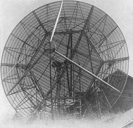
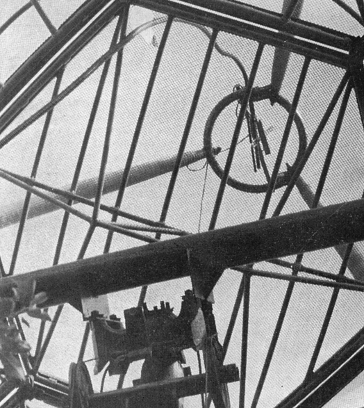
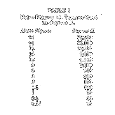 Last
month we talked about noise figure and temperature, the point being the
inconsistency between noise-figure improvement numbers and signal-to-noise
improvements when your receiver noise figure gets below 6 dB. The chart in
Table I will save the effort of converting receiver noise figures back to
temperature. We pointed out that a 420-Mc beam antenna might have a
temperature of 100-degrees K. If we take a feedline temperature of 70
degrees K, our combined antenna-feedline temperature would he 170-degrees
K. This assumes a good beam tilted up 3 degrees or so from the horizon and
a feedline with something less than one db. attenuation. If we feed this
nice antenna system into a 6 dB noise-figure receiver we end up with a
system temperature of 170-degrees K plus 838-degrees K (see 6dB n.f. in
Table I) equals 1008-degrees K. So far the majority of our system noise is
contributed by our receiver. We can easily obtain a 3 dB improvement in
signal to noise by dropping our receiver noise temperature to 334-degrees
K for a system temperature of 504 degrees. Note that the noise figure only
went down to 2.7 dB for this 3 dB improvement. To get another 3 dB
signal-to-noise improvement we must drop the system temperature to
252-degrees K. Now this would be easy if we had only receiver noise to
contend with. Unfortunately, we have our antenna-feed- line temperature
fixed at 170-degrees K. In order to get the system down to 252-degrees K,
we have to drop the receiver to 82-degrees K. Referring again to Table 1,
we find about 1.25 dB n.f. If our front end is a paramp this is still
pretty easy and we find that for a 4.75 dB improvement in noise figure we
obtained a 6 dB signal-to-noise improvement. On the other hand that
70-degree K feedline temperature has now become a big factor in our system
noise. With an 838-degree K (6 dB) front end, 70 degrees more or less
means nothing in terms of signal to noise. With a 252-degree K system it
starts to hurt. If we eliminate the feedline loss by mounting the
preamplifier at the antenna, we could get by with a 152-degree K front
end. This is just under 2 dB n.f. and can be just obtained if we make use
of T.I.’s latest germanium transistors (TIX100M). Note that our antenna is
now contributing a large part of our system temperature. For tropo-type
contacts we have to live with it. For a satellite or moonbounce efforts we
get a break. Under good conditions the antenna temperature, when aimed
well above the horizon, might get as low as 20-degrees K. In this ease,
our antenna mounted preamp would give us a system temperature of
172-degrees Kelvin - a signal-to-noise gain of 7.5 dB for a noise-figure
improvement of 4.2 dB. It is interesting to observe that eliminating the
feedline loss and tilting the antenna would yield less than 1 dB in signal
to noise improvement, with a 6 dB n.f. preamp, a negligible amount. The
important thing is the improvement in signal-to-noise as the system noise
temperature drops. Each time you cut your system temperature in half you
improve your signal-to-noise ratio by 3 dB. With a poor receiver this is
the same as improving your noise figure by 3 dB, i.e., 18 dB to 15 dB is a
change from 18,000-degrees K to 9000-degrees K. 15 dB to 12 dB cuts the
noise temperature in half again to 4512-degrees K. When you get down to 3
dB noise figure, however, a 3 dB signal-to-noise improvement requires only
a little more than 1.5 dB n.f. improvement, depending on your antenna and
feedline temperature. Now, I am aware that you quit paying attention as
soon as I mentioned the TIX100M transistors. To relieve your anxiety I
will point out that next month you will get all the pertinent details on
how to get the transistors and how to build the preamp. Be patient.
Meanwhile, if you are in the paramp building or thinking stage you can get
some good information on 3-part circulators for 432 or 1296 Mc by dropping
a line to Melabs, 3300 Hillview Ave., Palo Alto, California, and asking
for details on their amateur model J-6970 (432 Mc) or J-6979 (1296 Mc). I
also have a copy of their specs (courtesy of K6HCP) and will be glad to
send same to anyone interested.
Last
month we talked about noise figure and temperature, the point being the
inconsistency between noise-figure improvement numbers and signal-to-noise
improvements when your receiver noise figure gets below 6 dB. The chart in
Table I will save the effort of converting receiver noise figures back to
temperature. We pointed out that a 420-Mc beam antenna might have a
temperature of 100-degrees K. If we take a feedline temperature of 70
degrees K, our combined antenna-feedline temperature would he 170-degrees
K. This assumes a good beam tilted up 3 degrees or so from the horizon and
a feedline with something less than one db. attenuation. If we feed this
nice antenna system into a 6 dB noise-figure receiver we end up with a
system temperature of 170-degrees K plus 838-degrees K (see 6dB n.f. in
Table I) equals 1008-degrees K. So far the majority of our system noise is
contributed by our receiver. We can easily obtain a 3 dB improvement in
signal to noise by dropping our receiver noise temperature to 334-degrees
K for a system temperature of 504 degrees. Note that the noise figure only
went down to 2.7 dB for this 3 dB improvement. To get another 3 dB
signal-to-noise improvement we must drop the system temperature to
252-degrees K. Now this would be easy if we had only receiver noise to
contend with. Unfortunately, we have our antenna-feed- line temperature
fixed at 170-degrees K. In order to get the system down to 252-degrees K,
we have to drop the receiver to 82-degrees K. Referring again to Table 1,
we find about 1.25 dB n.f. If our front end is a paramp this is still
pretty easy and we find that for a 4.75 dB improvement in noise figure we
obtained a 6 dB signal-to-noise improvement. On the other hand that
70-degree K feedline temperature has now become a big factor in our system
noise. With an 838-degree K (6 dB) front end, 70 degrees more or less
means nothing in terms of signal to noise. With a 252-degree K system it
starts to hurt. If we eliminate the feedline loss by mounting the
preamplifier at the antenna, we could get by with a 152-degree K front
end. This is just under 2 dB n.f. and can be just obtained if we make use
of T.I.’s latest germanium transistors (TIX100M). Note that our antenna is
now contributing a large part of our system temperature. For tropo-type
contacts we have to live with it. For a satellite or moonbounce efforts we
get a break. Under good conditions the antenna temperature, when aimed
well above the horizon, might get as low as 20-degrees K. In this ease,
our antenna mounted preamp would give us a system temperature of
172-degrees Kelvin - a signal-to-noise gain of 7.5 dB for a noise-figure
improvement of 4.2 dB. It is interesting to observe that eliminating the
feedline loss and tilting the antenna would yield less than 1 dB in signal
to noise improvement, with a 6 dB n.f. preamp, a negligible amount. The
important thing is the improvement in signal-to-noise as the system noise
temperature drops. Each time you cut your system temperature in half you
improve your signal-to-noise ratio by 3 dB. With a poor receiver this is
the same as improving your noise figure by 3 dB, i.e., 18 dB to 15 dB is a
change from 18,000-degrees K to 9000-degrees K. 15 dB to 12 dB cuts the
noise temperature in half again to 4512-degrees K. When you get down to 3
dB noise figure, however, a 3 dB signal-to-noise improvement requires only
a little more than 1.5 dB n.f. improvement, depending on your antenna and
feedline temperature. Now, I am aware that you quit paying attention as
soon as I mentioned the TIX100M transistors. To relieve your anxiety I
will point out that next month you will get all the pertinent details on
how to get the transistors and how to build the preamp. Be patient.
Meanwhile, if you are in the paramp building or thinking stage you can get
some good information on 3-part circulators for 432 or 1296 Mc by dropping
a line to Melabs, 3300 Hillview Ave., Palo Alto, California, and asking
for details on their amateur model J-6970 (432 Mc) or J-6979 (1296 Mc). I
also have a copy of their specs (courtesy of K6HCP) and will be glad to
send same to anyone interested.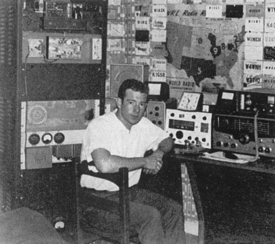
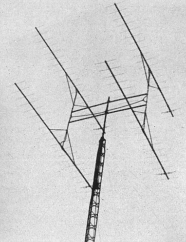
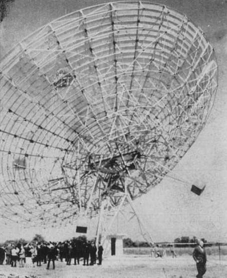
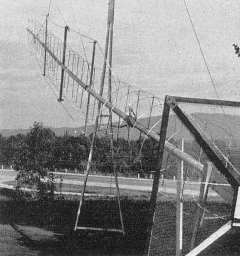
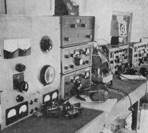
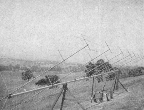
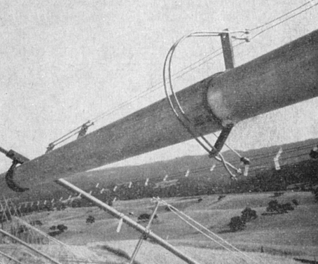
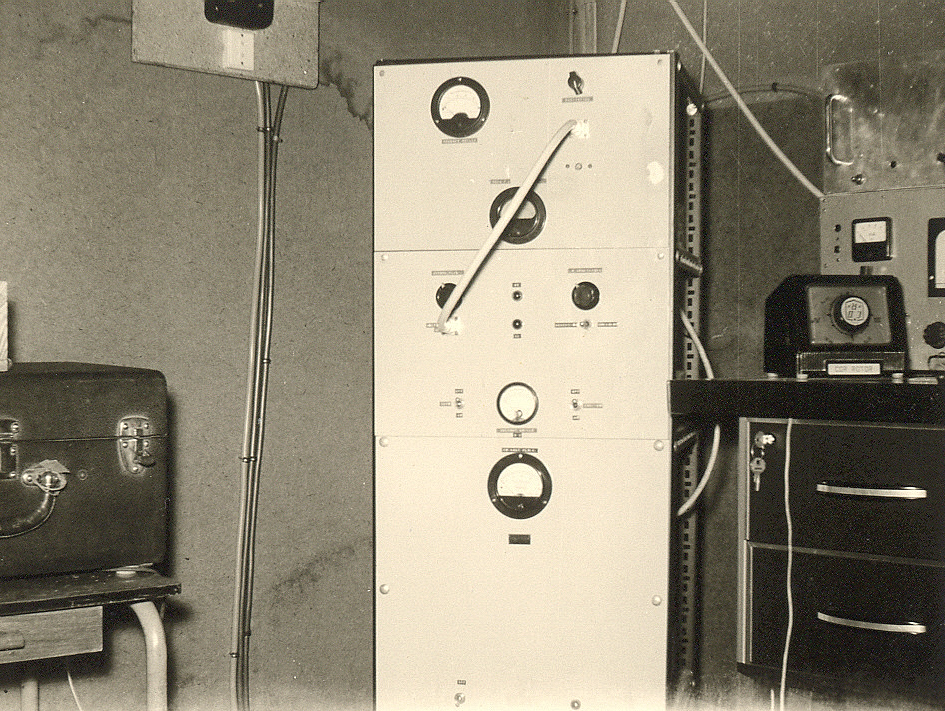
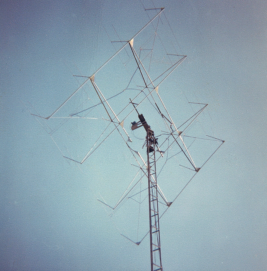
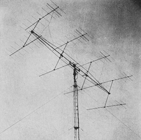
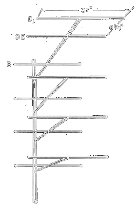
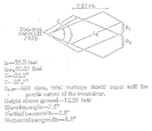
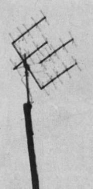
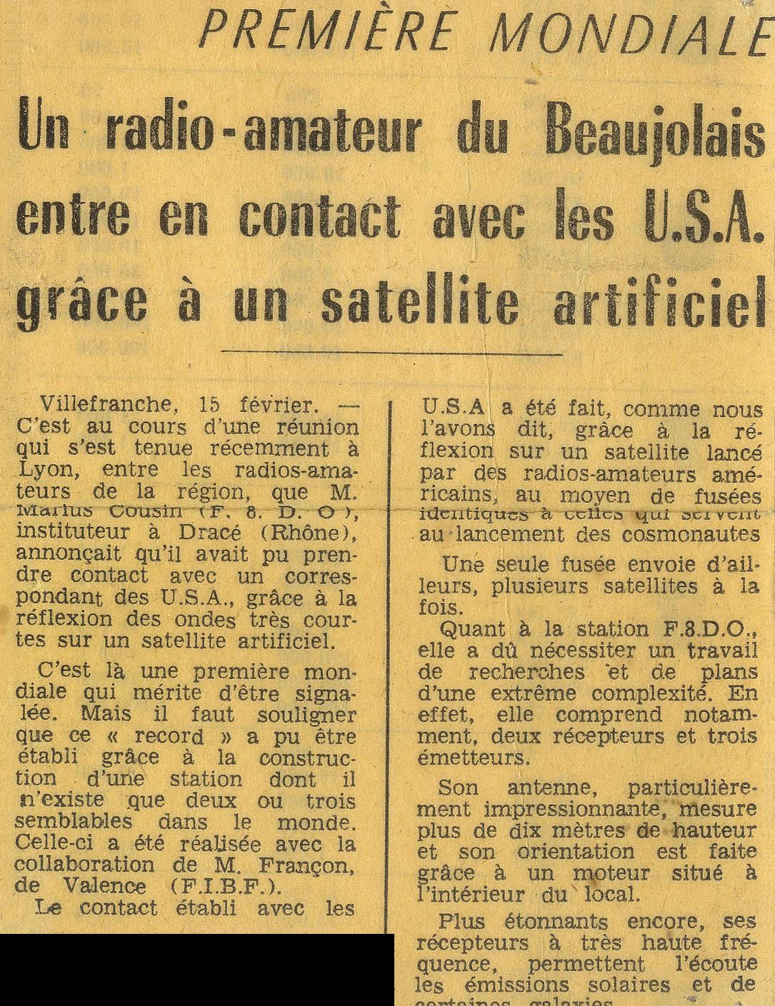
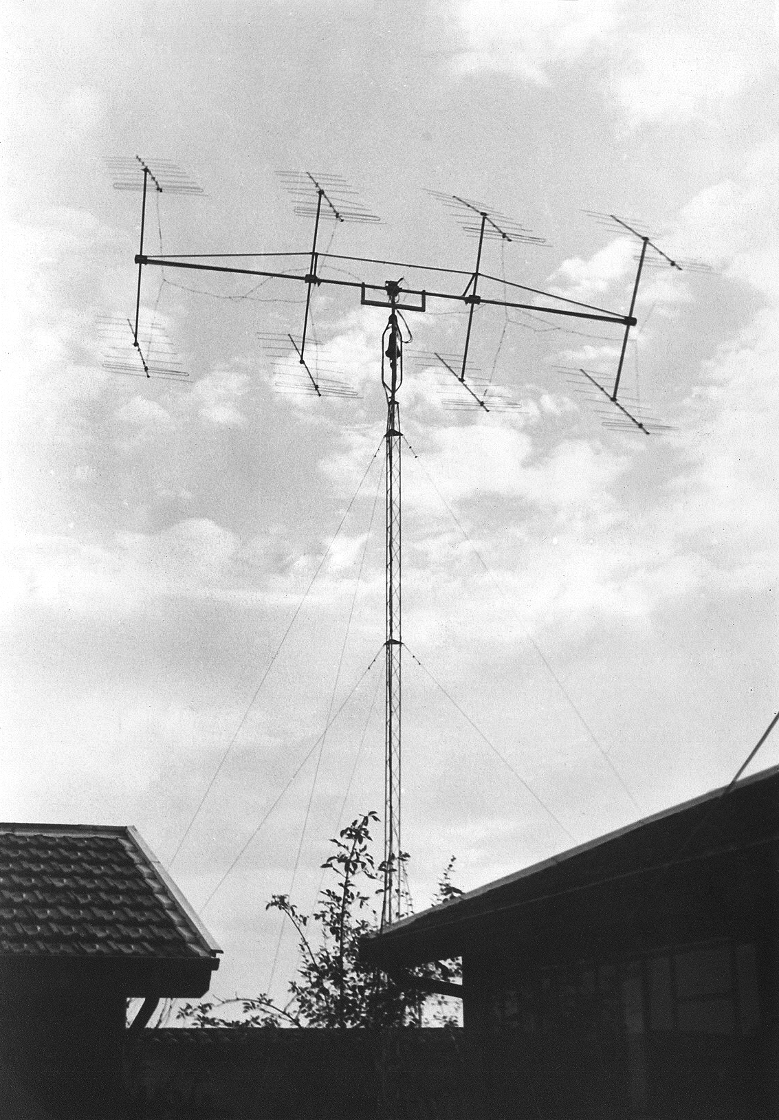
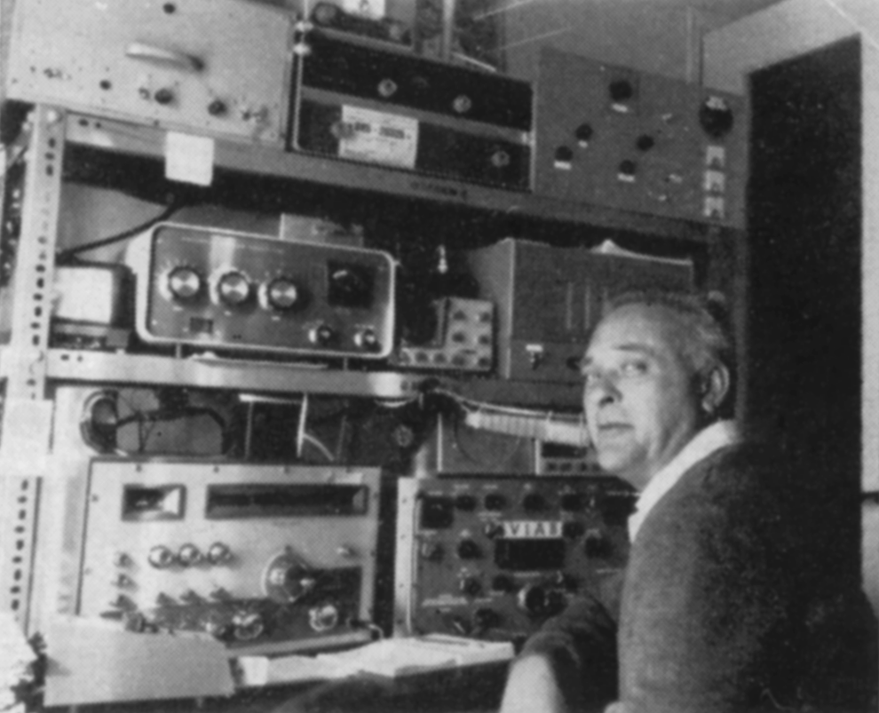
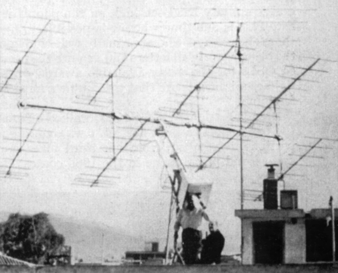
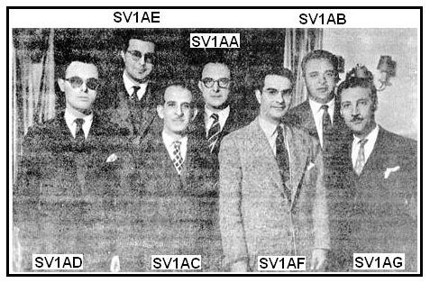 As
for keraiomani on the roof, with no reason! From G5RV up a foursome of
Yagi for 23 cm. Yagi for 6 meters, on 2 meters and 70 centimeters.
As
for keraiomani on the roof, with no reason! From G5RV up a foursome of
Yagi for 23 cm. Yagi for 6 meters, on 2 meters and 70 centimeters.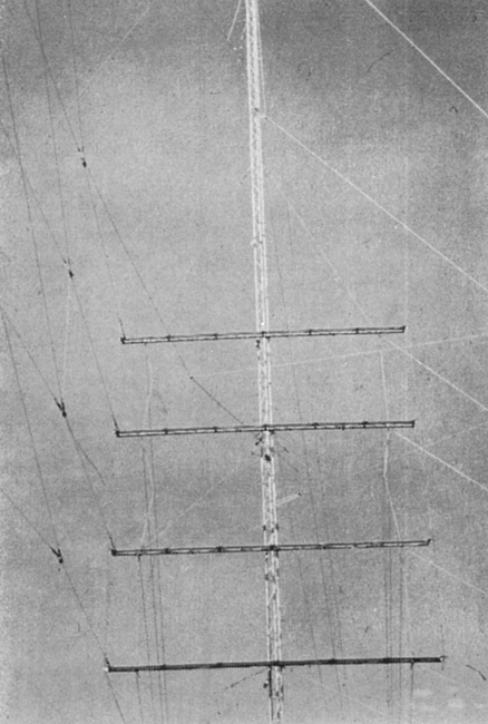
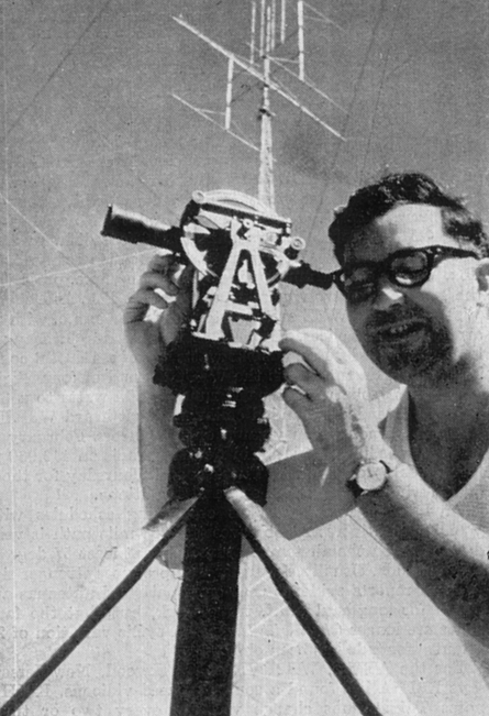
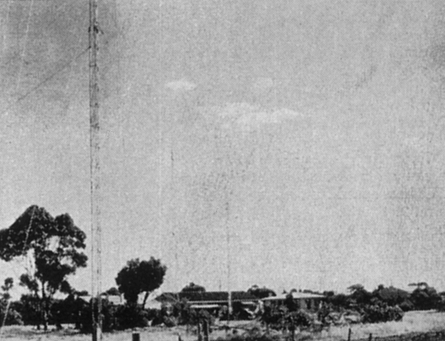
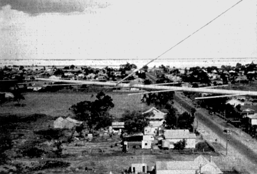
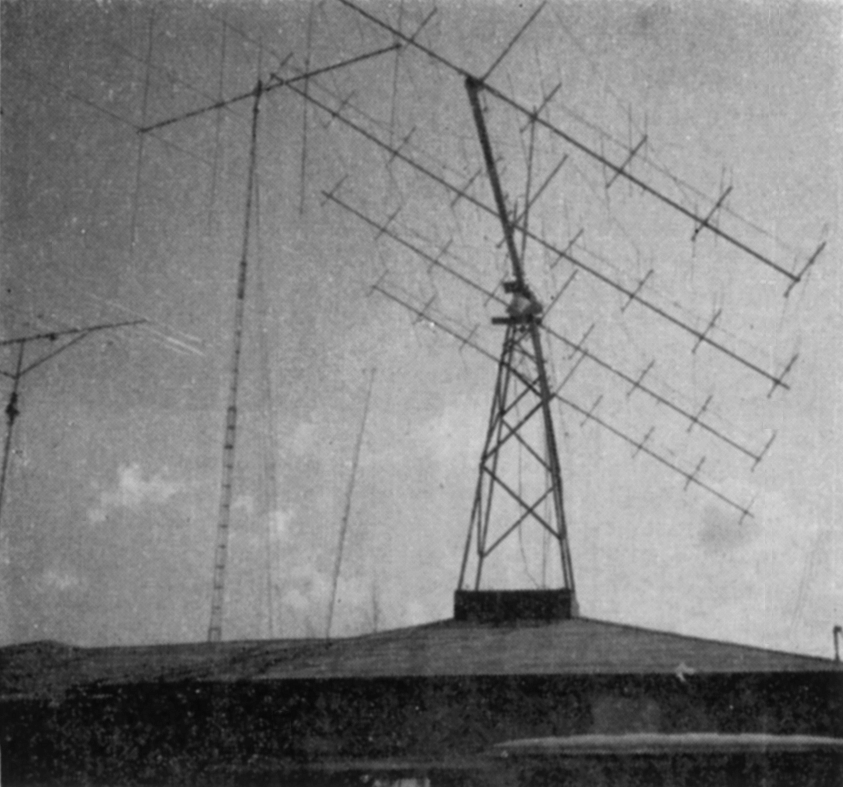
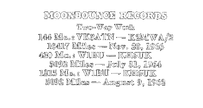 Looking
far into the future, Nick Marshall, W6OLO/2 and formerly technical
director of the Oscar program, says another amateur space communications
project is developing called NASTAR for the Nassau Satellite Tracking
Amateur Radio Society. The organization hopes to put a ham transponder
package on the moon during the third manned U. S. landing on the lunar
surface.
Looking
far into the future, Nick Marshall, W6OLO/2 and formerly technical
director of the Oscar program, says another amateur space communications
project is developing called NASTAR for the Nassau Satellite Tracking
Amateur Radio Society. The organization hopes to put a ham transponder
package on the moon during the third manned U. S. landing on the lunar
surface.

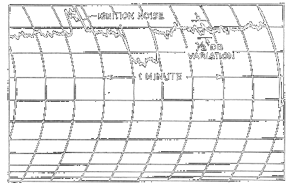
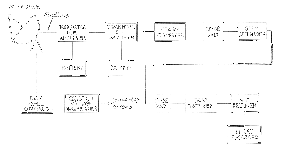
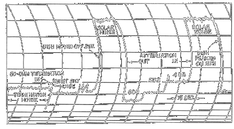
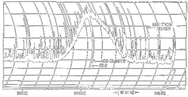
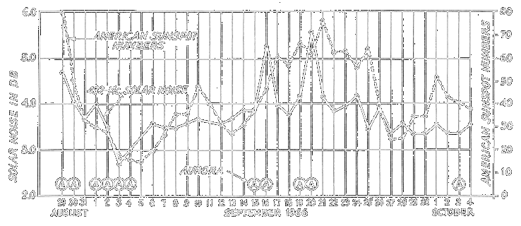
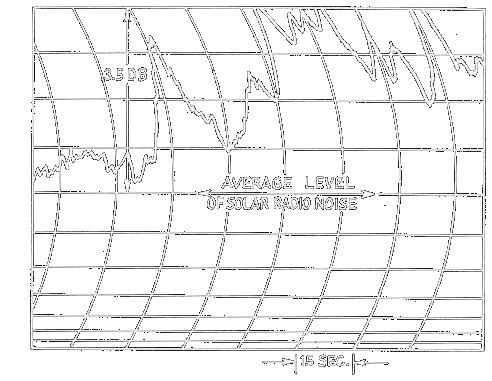
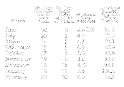
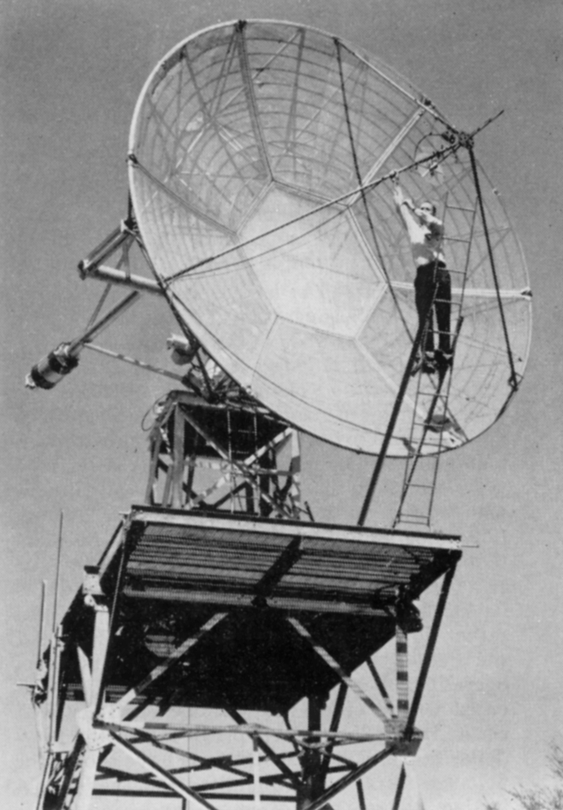
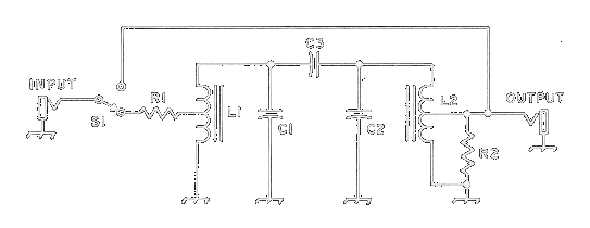
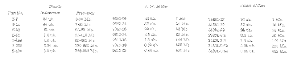
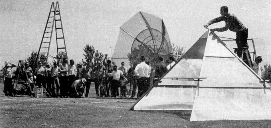
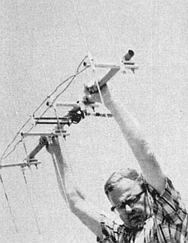
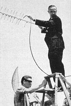
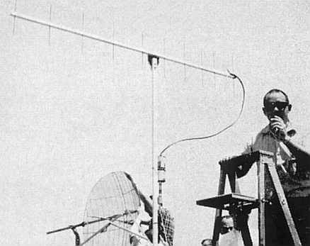 At the left center, W6TZJ registers
consternation upon seeing his 432 Mc commercial collinear showing only
10.6 dB gain. Next, VE3DNR juggles a yagi made with quad-type elements.
Right center, WA6GYD demonstrates “a lot for a little” with a wood-boom
432 Mc yagi (from the ARRL V.H.F. Manual) that showed 12 dB.
At the left center, W6TZJ registers
consternation upon seeing his 432 Mc commercial collinear showing only
10.6 dB gain. Next, VE3DNR juggles a yagi made with quad-type elements.
Right center, WA6GYD demonstrates “a lot for a little” with a wood-boom
432 Mc yagi (from the ARRL V.H.F. Manual) that showed 12 dB.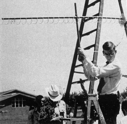
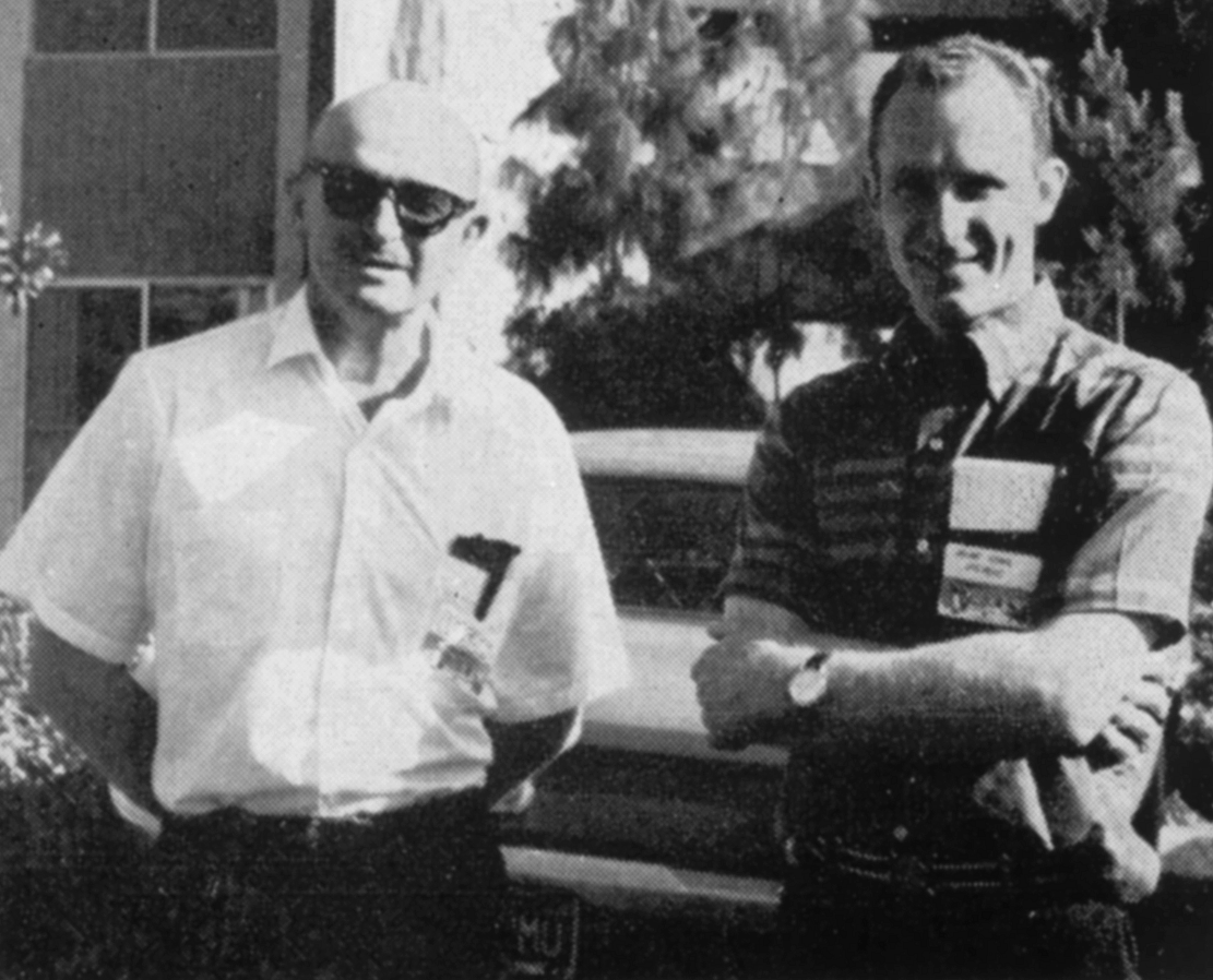
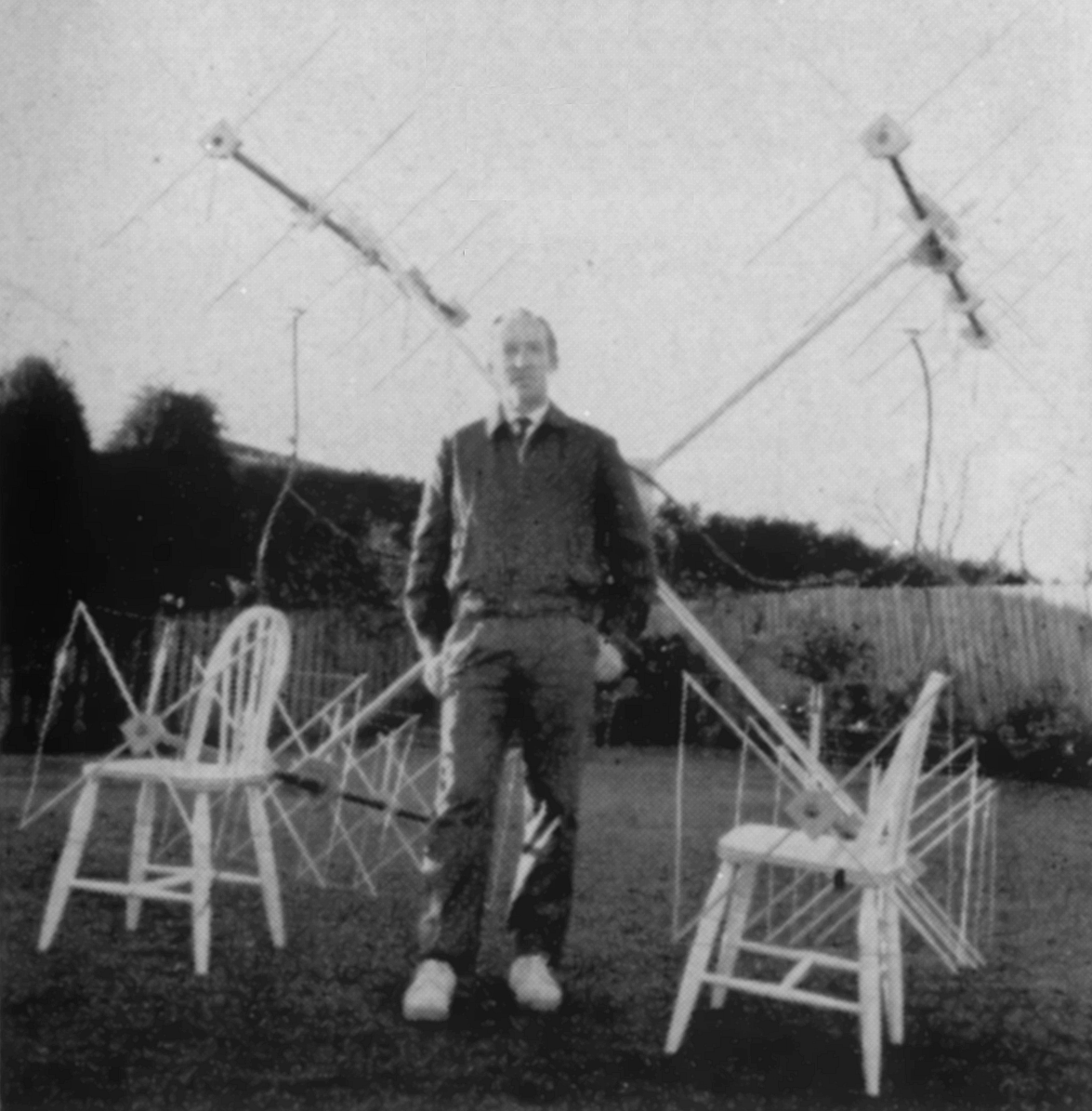
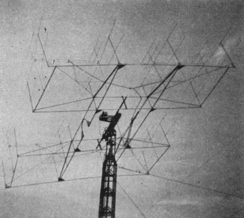
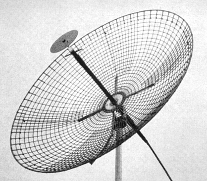
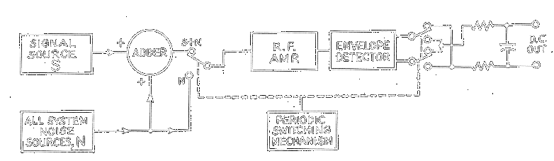
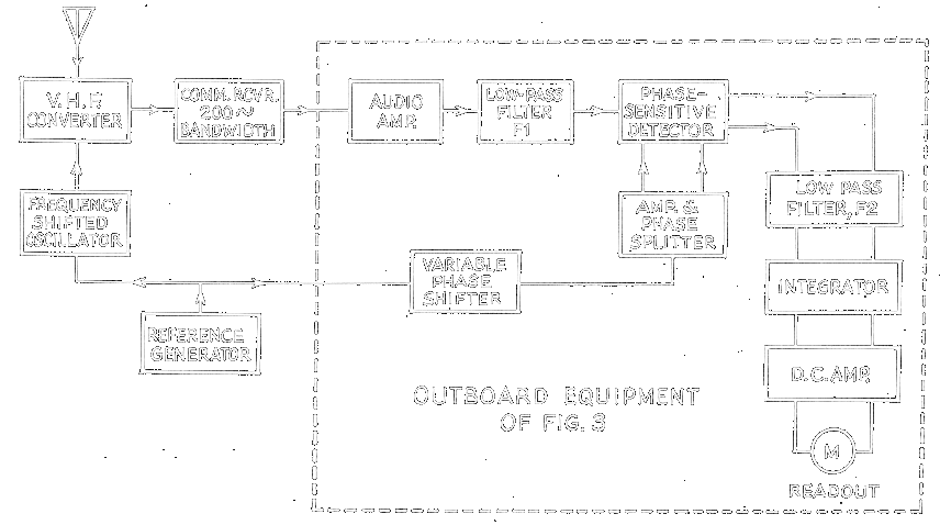
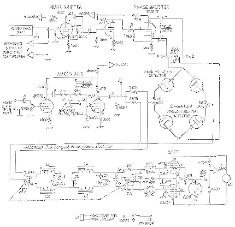
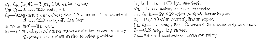
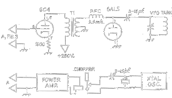
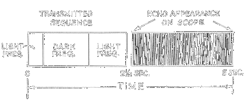
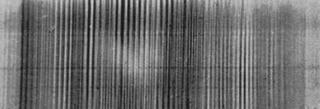
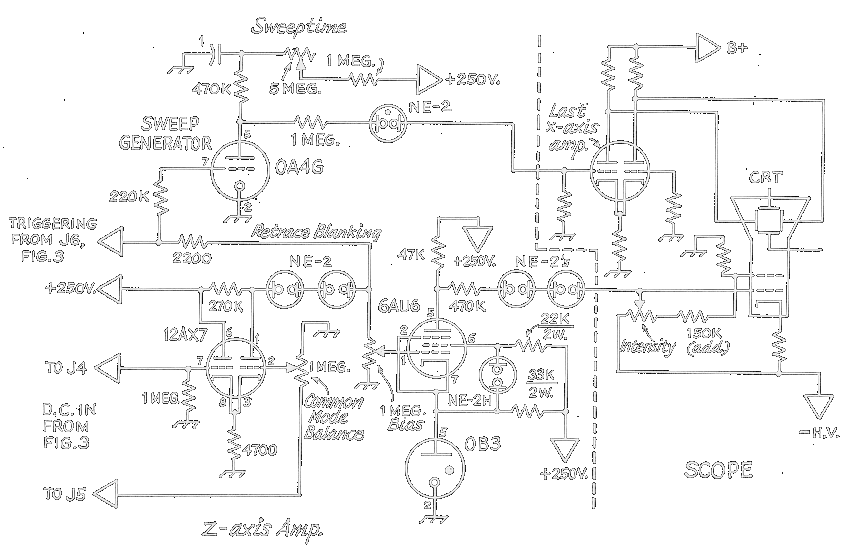
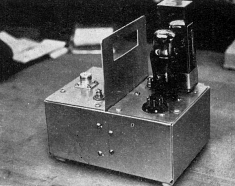
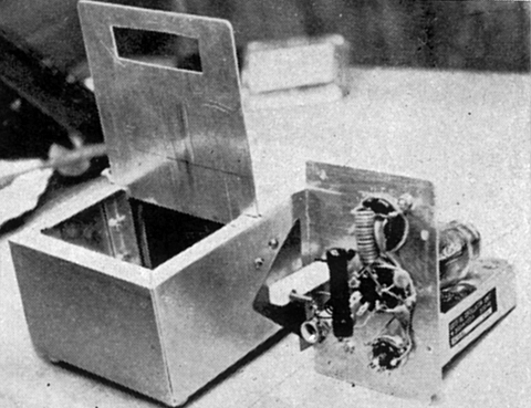 Fig. 7 - Weak-signal generator used for
testing the receiving equipment. Output is varied by moving the vane shown
at the center of the assembly. The 500 kc oscillator and voltage-regulator
tube are at the right side of the vane in the assembled view, left. The
interior is shown at the right.
Fig. 7 - Weak-signal generator used for
testing the receiving equipment. Output is varied by moving the vane shown
at the center of the assembly. The 500 kc oscillator and voltage-regulator
tube are at the right side of the vane in the assembled view, left. The
interior is shown at the right.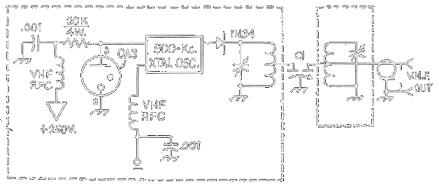
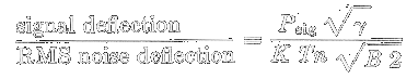
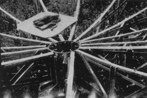
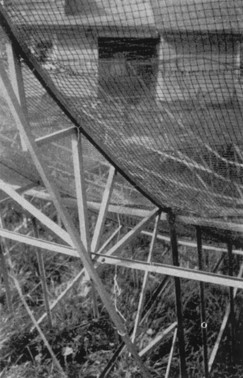
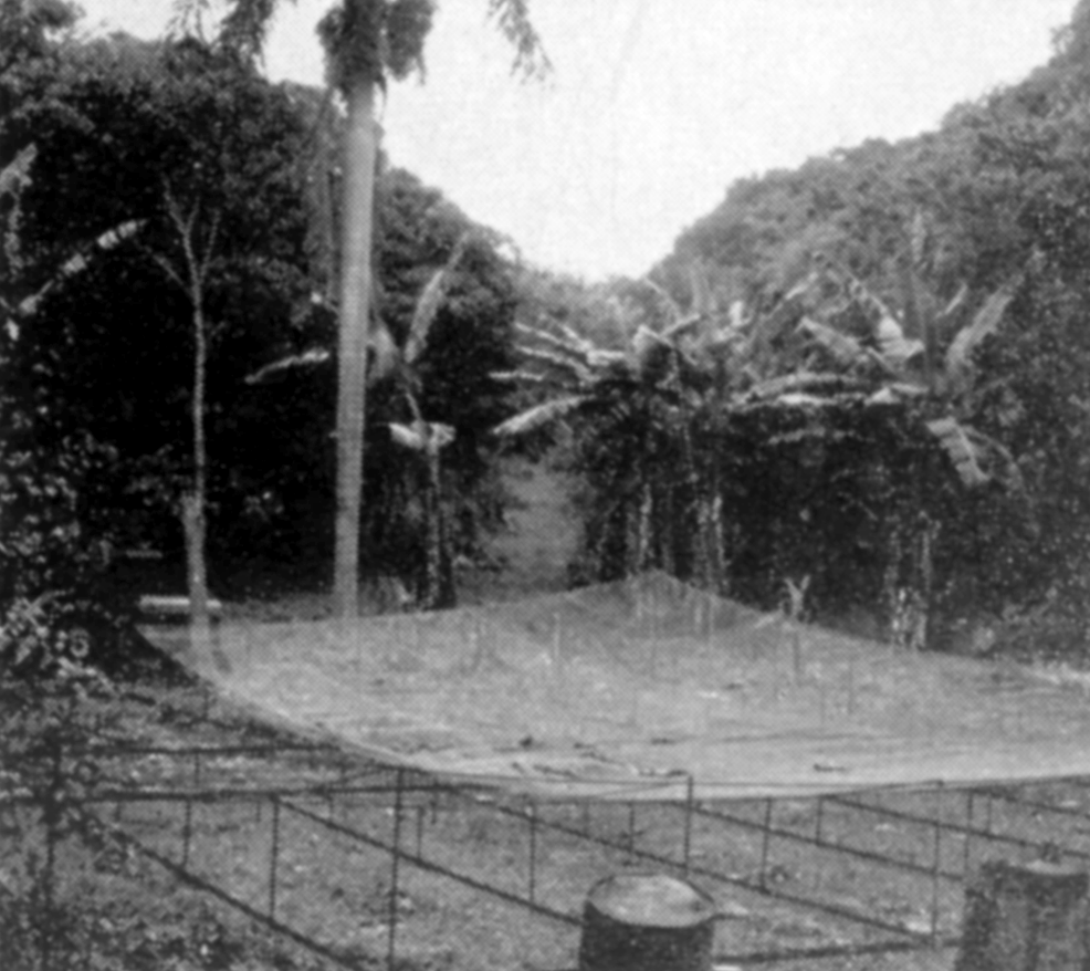
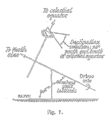 If
only e.m.e. is contemplated, a polar (or equatorial) mount would be a wise
selection as it requires only one drive mechanism for tracking and some
form of manually tilting the array slightly from day to day to set the
declination (Declination: Angle in degrees north or south of the
celestial Equator (the circle that would be formed at a right angle around
the polar axis). To accomplish this, your antenna mast or tower must be
mounted parallel to the axis of the earth. Thus, if your station location
is at 35° north, the mast would be fixed at an angle of 35° from the
earth’s surface at such location, oriented in a north-south direction (see
fig. 1.). The declination (manually-tilted axis) changes from day to day.
Information may be found in The American Ephemeris and Nautical Almanac,
1968, available through the Superintendent of Documents, U.S. Government
Printing Office, Washington, D.C. for a nominal price. All that is
necessary now is that your drive mechanism rotate the antenna at a rate of
15° per hour to track the moon.
If
only e.m.e. is contemplated, a polar (or equatorial) mount would be a wise
selection as it requires only one drive mechanism for tracking and some
form of manually tilting the array slightly from day to day to set the
declination (Declination: Angle in degrees north or south of the
celestial Equator (the circle that would be formed at a right angle around
the polar axis). To accomplish this, your antenna mast or tower must be
mounted parallel to the axis of the earth. Thus, if your station location
is at 35° north, the mast would be fixed at an angle of 35° from the
earth’s surface at such location, oriented in a north-south direction (see
fig. 1.). The declination (manually-tilted axis) changes from day to day.
Information may be found in The American Ephemeris and Nautical Almanac,
1968, available through the Superintendent of Documents, U.S. Government
Printing Office, Washington, D.C. for a nominal price. All that is
necessary now is that your drive mechanism rotate the antenna at a rate of
15° per hour to track the moon.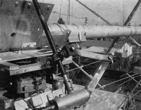
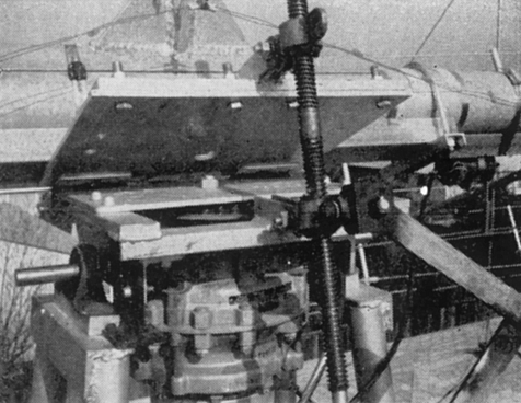

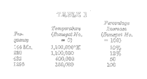 The
radio astronomer would measure N, A, and the antenna parameters, and then
knowing these would measure Ts daily by measuring daily values of D. As
hams, we are probably more interested in measuring the antenna parameters,
or in monitoring our receiving system to make sure everything is working
the way it should. This way leads to some trouble, simply because we don’t
know enough about Ts. At frequencies below about 1000 Mc, the apparent
solar temperature isn’t very well known for several reasons. The first is
that not too many solar observatories have measured solar temperatures
daily over a long period of time in this frequency range. While Potsdam,
Ottawa, and Toyokawa, among others, measure daily solar temperatures
between 1,000 and 10,000 Mc, and have over most of a sunspot cycle by now,
not very many protracted measurements are available for the frequencies we
are talking about. The second reason is that the solar temperature varies
from day to day. Radiation at these frequencies comes from high in the
solar atmosphere, and there is still much to be learned about this region
of the sun. Therefore, solar temperatures often show little correlation
with sunspot number, which is really a measure of activity in the lower
part of the sun’s atmosphere.
The
radio astronomer would measure N, A, and the antenna parameters, and then
knowing these would measure Ts daily by measuring daily values of D. As
hams, we are probably more interested in measuring the antenna parameters,
or in monitoring our receiving system to make sure everything is working
the way it should. This way leads to some trouble, simply because we don’t
know enough about Ts. At frequencies below about 1000 Mc, the apparent
solar temperature isn’t very well known for several reasons. The first is
that not too many solar observatories have measured solar temperatures
daily over a long period of time in this frequency range. While Potsdam,
Ottawa, and Toyokawa, among others, measure daily solar temperatures
between 1,000 and 10,000 Mc, and have over most of a sunspot cycle by now,
not very many protracted measurements are available for the frequencies we
are talking about. The second reason is that the solar temperature varies
from day to day. Radiation at these frequencies comes from high in the
solar atmosphere, and there is still much to be learned about this region
of the sun. Therefore, solar temperatures often show little correlation
with sunspot number, which is really a measure of activity in the lower
part of the sun’s atmosphere. 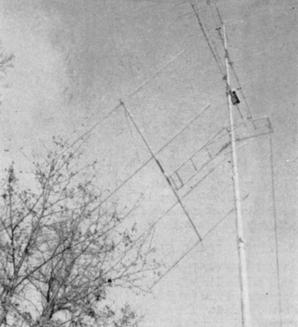
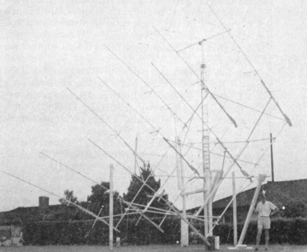
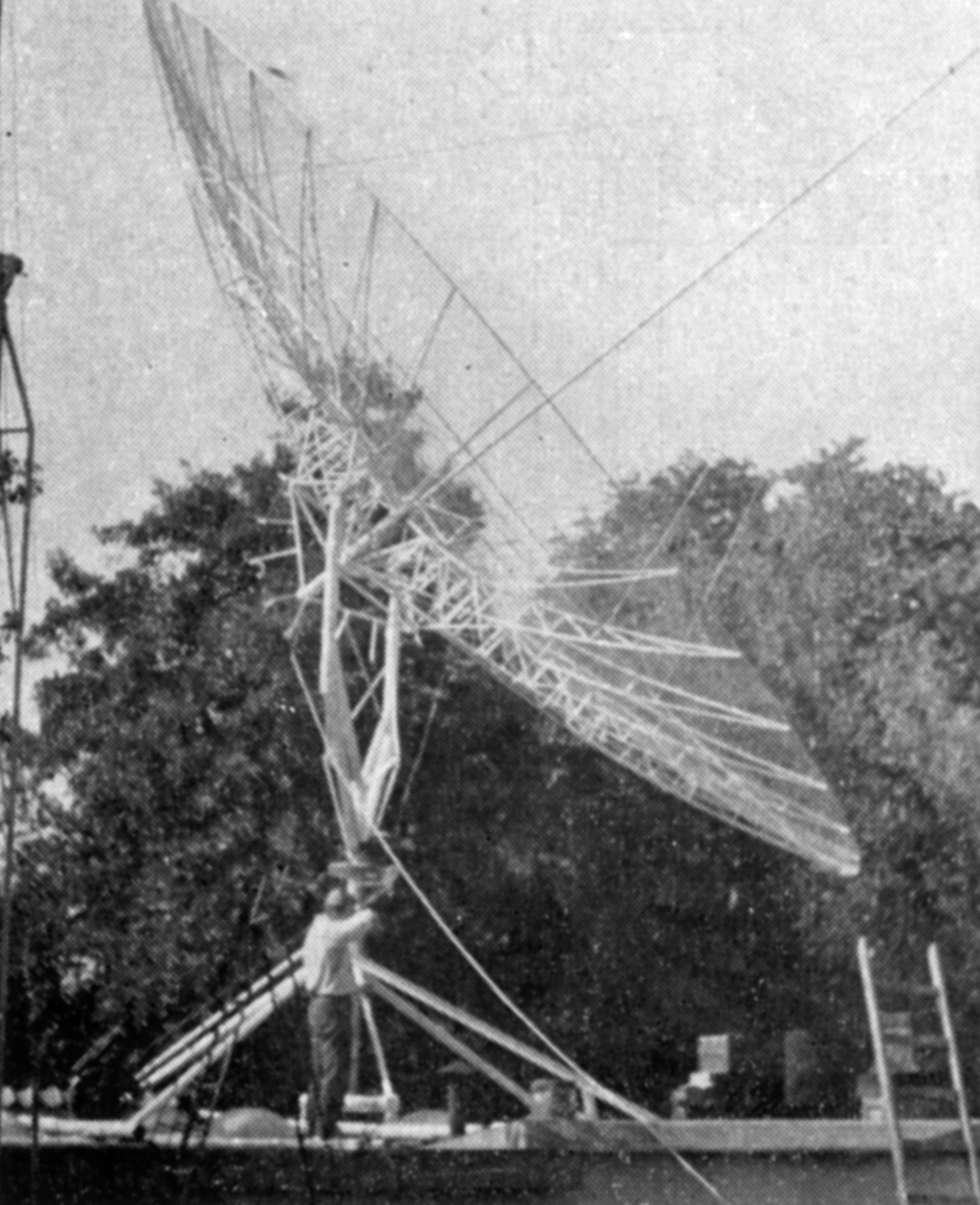
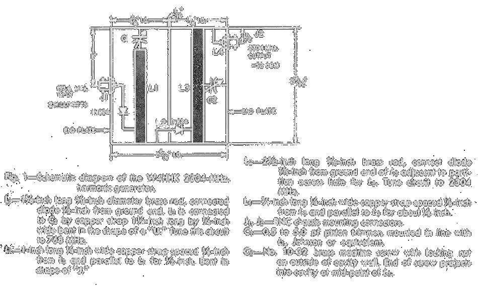
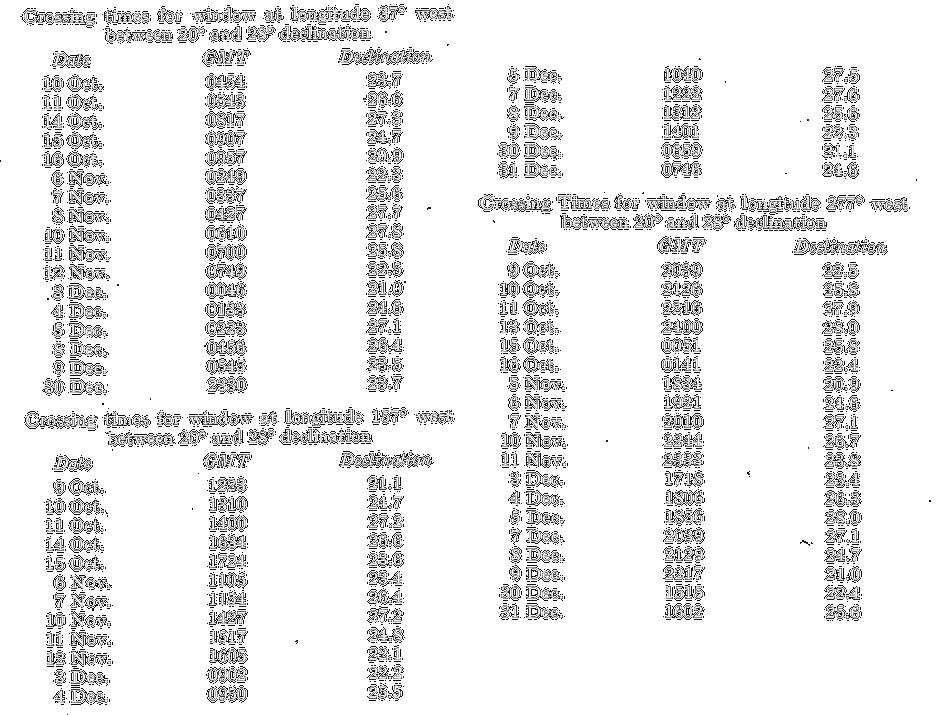
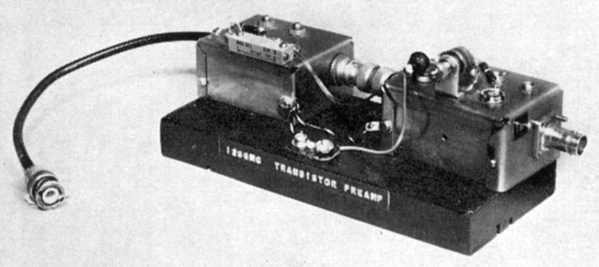
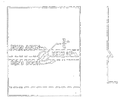
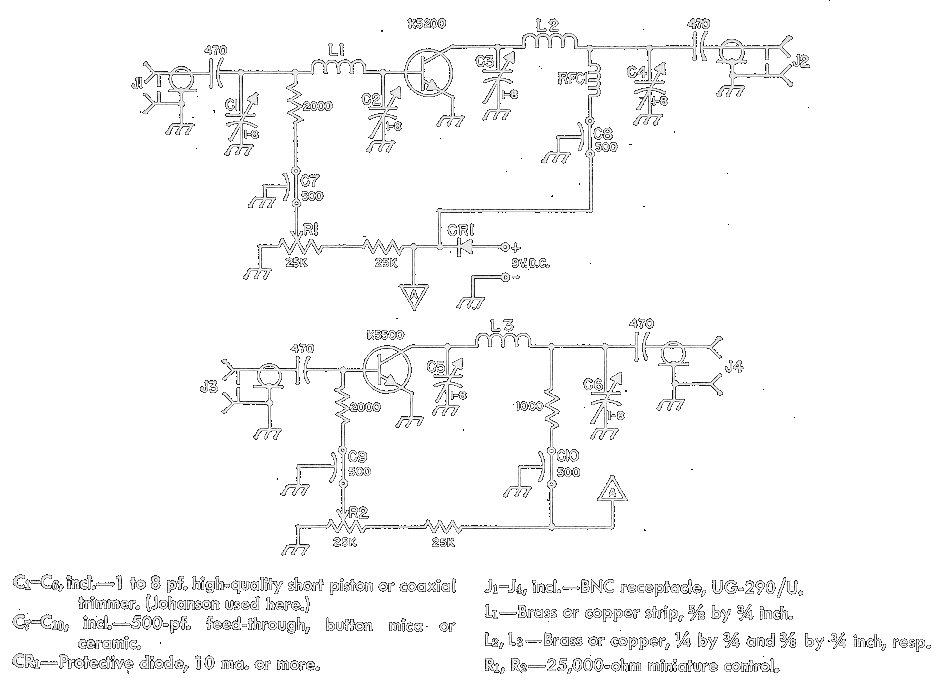
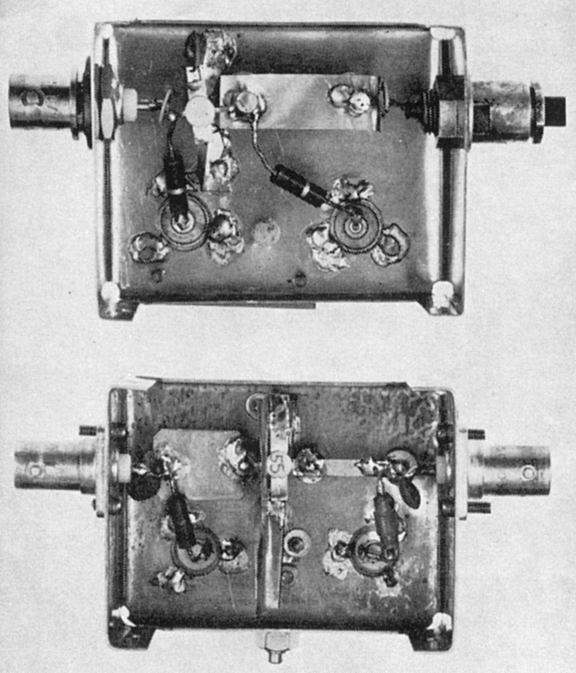
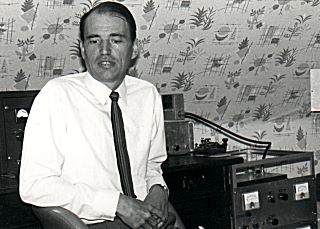 SM7BAE
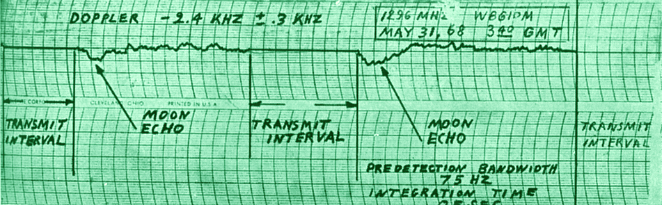
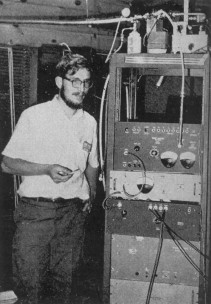
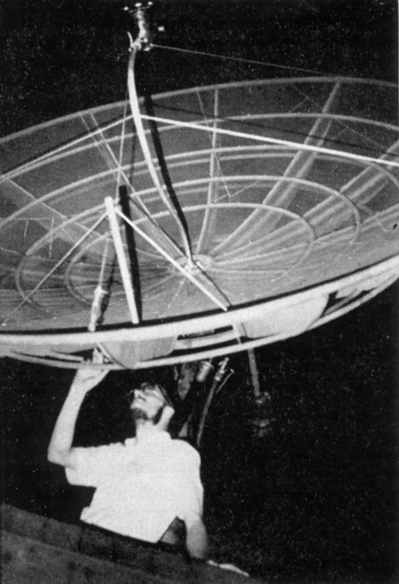
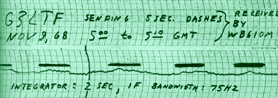
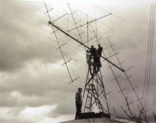
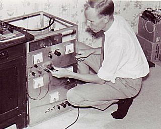 Yngve SM7BCX
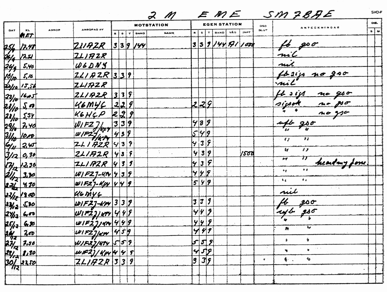
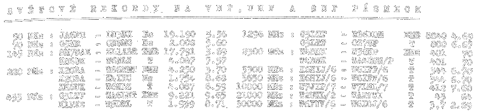
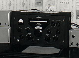
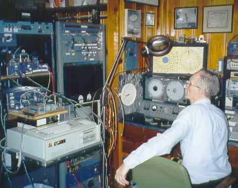
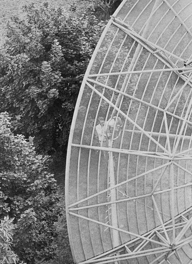
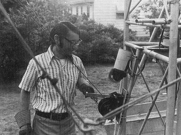
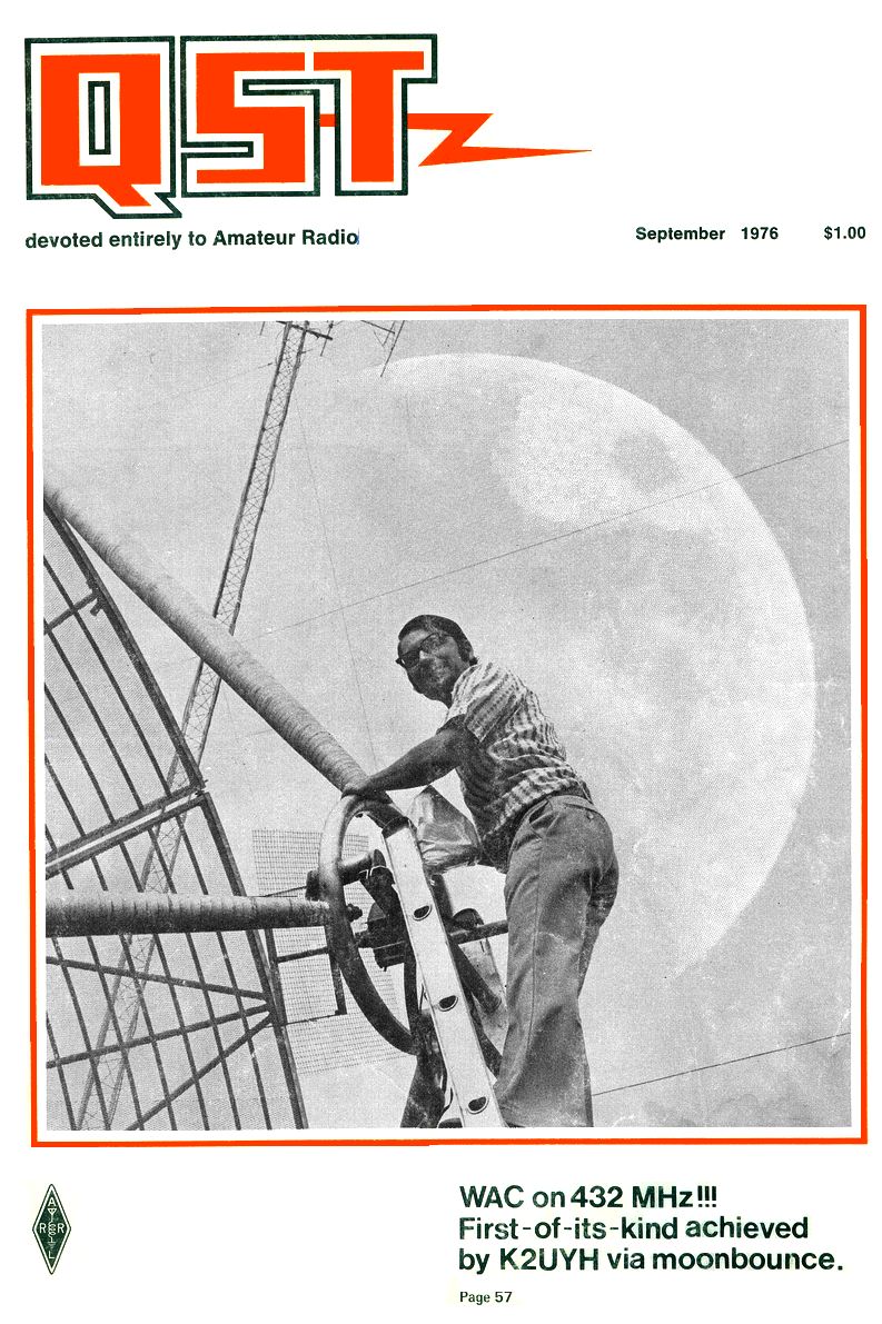
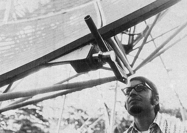
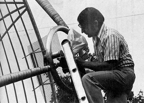
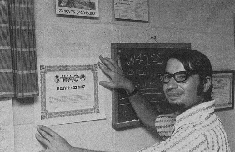
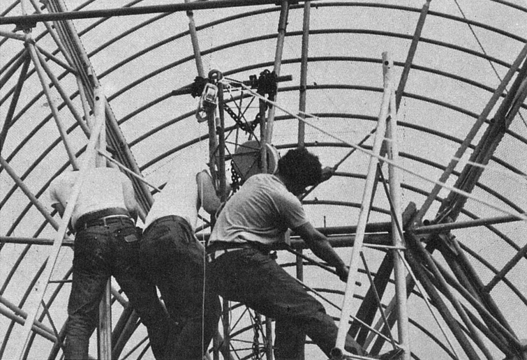
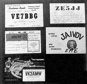
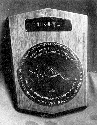
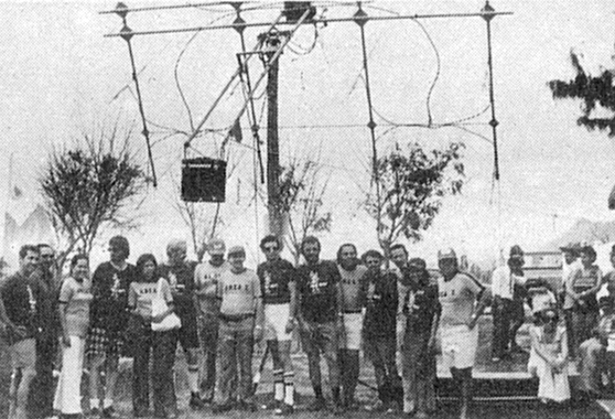
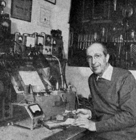