|
Sequencer for installation into a PA - 10 years after.. It is already more, than 10 years, when I developed this device and start to use it in our equipments. At the present time, hundreds operators use it. Even no modification was needed, what is always appreciated for designer. However still are there some reasons, why would be useful to revisite this design. Beside new PCB the reason i tis a opportunity to clarify few different systems of sequencers, used in the ham radio praxis. Why such simple sequencer? Because (aside my vanity, hi), I believe it is the best option. Of course, in the hamradio are used:
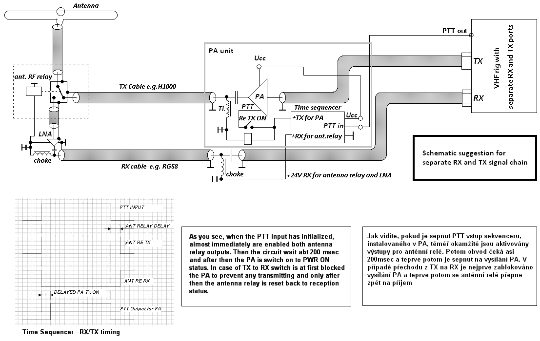
Sequencer with relays is a fast solution and you may to setup it within few tens of minutes. The are immune to RF electromagnetic field. But any relay is relatively very unreliable device – delay is not constant, humidity, dust and temperature has bad impact to the life time and connectivity of contacts, mechanical parts have limited durability. If you want to operate you expensive gear by such device, it is a bit hazardous and earlier or later on you will lost it. Much better are sequencers with comparators, where the delay is created by some RC time constant, which is followed by more comparators, which connects different circuits. But such comparators have switching voltage variance few milivolts only and in case of humidity, dust and ingress of strong RF field the results may create some expensive crash as well as. There is many of such sequencers in use and mostly without any troubles, but such potential problem exist. So i tis good to know abt. pros and cons. Sequencers with simple CMOS ICs looks stupid, but because such ICs may use supply up to 15V, they are quite reliable and robust – even against local RF field due to high noise immunity. And because these components works up to 30MHz max, even the lowest VHF bands have no influence to it. Because i tis a static logic, any problem is easy detectable by simple voltage measure. However, present development favorize microchip controllers. Nothing against such solution – but dynamic régime of such controller could be target of influence from strong RF electromagnetic field, particularly due to low supply voltage 5 or even 3.3V. And any failure may created very expensive shame on your equipment. And beside o it, continuos run of microchip IC, may create RF noise – so bad option for EME. Due to it, if you intend use microchip controller (not only in sequencer), I would suggest to place such PCB into screened metal box and use feedthrough capacitors for all input/output connections, to prevent potential troubles. Second issue of the sequencer evaluation is the mode of use. Criteria for it is rather simple: sequencer should be installed in any PA, transverter, transverter, etc, not to be used as some „station sequencer“, which is interconnected by some small cable with each device in the transmitting chain! In such case, nobody may prevent from some „manipulation failure“ (when something was not connected properly in the time of transmitter activation), and beside it are well-known fatefully unreliable CINCH connectors. And such mistake may damage your gear in fraction of second. Due to it, design connectivity plan of all of your components such way, that in case of any failure or disconnection the whole chain will not work, BUT NEVER WILL BE DESTROYED! Part of it is for example the principle, that the antenna relay is always activated during RX mode and deactivated in case of TX! You will not believe, how many ham radio operators does not accept this simple tenet! And then they are surprised, that LNA, transverter or even SSPA is gone… To prevent such problem, much easier is installation of sequencer into any additional active device, connected to your transceiver! Of course with minimum or better no connectors and such PA control herself his own antenna relay and LNA (installed or on the antenna). I hope, such principles are well visible on such schematic: (click for full size)
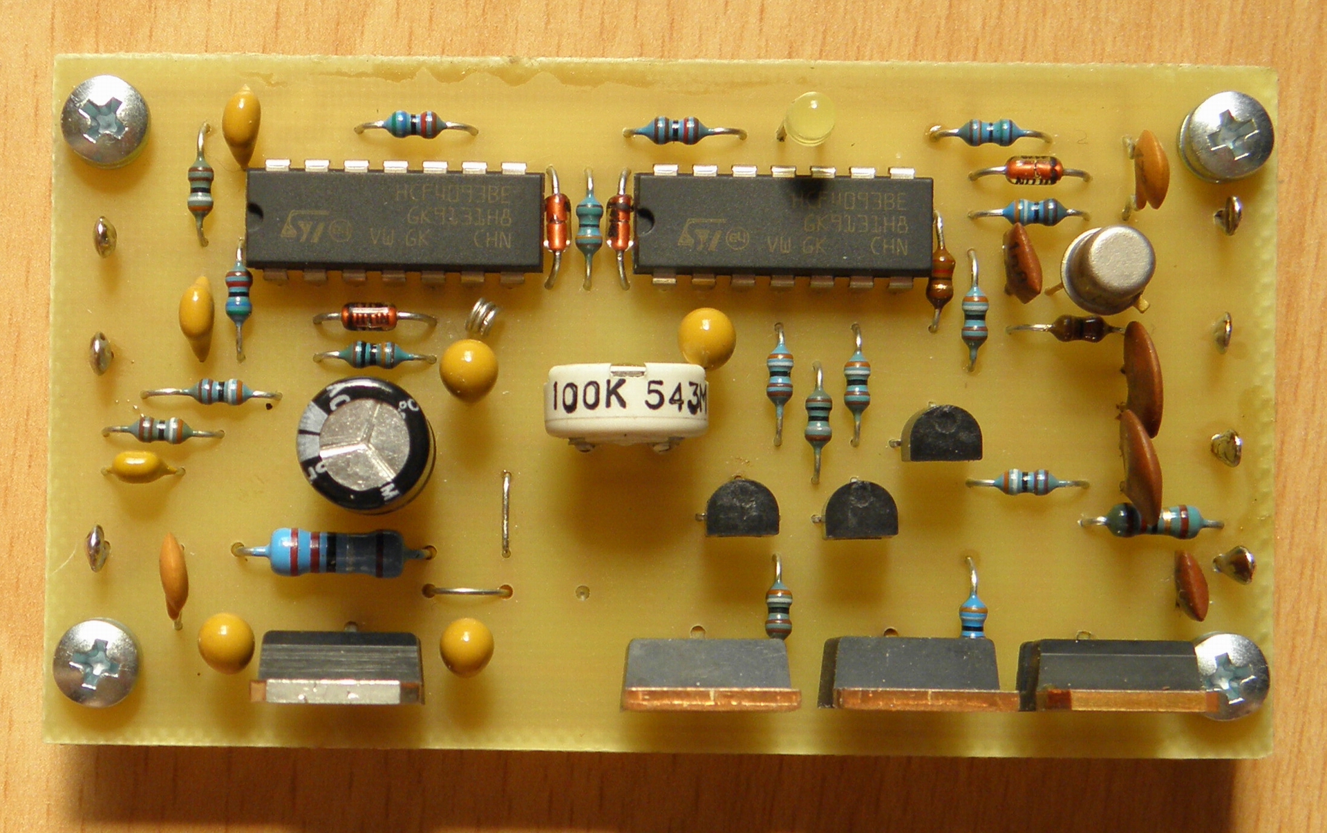
And for final – what is new in the sequencer design, compare to the previous version: nothing important! The PCB is (compare the previous one) more robust, additional PIN for blocking of PA has added (for example in case of high temp, or SWR) and delay adjust trimmer was replaced to the up to date one. PNP Darlingtons TIP125 you may replace by P-FET like IRF9530, however you need add some resistor (3k9) between S and G. Archaic transistors (like KF508) you may replace by any standard NPN type or even by BS170 FET. If you have an interest for PCB, let me know – I have few in a drawer. The schematic is here.
(click for full size)
|