|
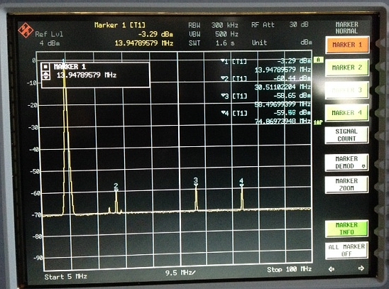
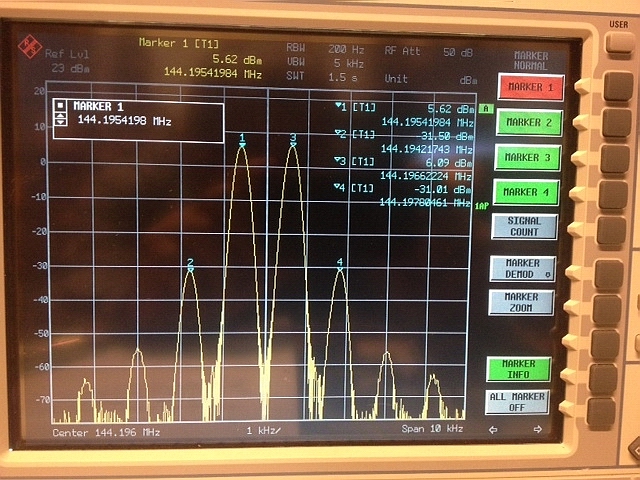
Any successful operation in the VHF Contests in high dense OK/OM/DL/S5 areas is not possible to conceive without suitable contest site, many aerials, team of experienced operators and - of course - the best technology. But except the last condition, the rest is rather issue of financing and management, however in case of technology is needed broadband knowledge and creativity. And while the Czech teams stricly defend theirs technical solutions, Slovak Contest team OM3W gave us possibility look into theirs kitchen. It is very appreciated! Lets look what they are using: At first few words about OM3W - this team of VHF Contest enthusiasts have a really rich history. Remind extraordinary Slovak result in VHF Contest 1981 (at that time as OK3KGW), building of contesting site on Vršatec/Chmeľová hill in JN99BB and many of cuccessful contests results from this area and lately even move of all contest "circus" directly at Czech-Slovak border to Portáš JN99CH contesting site, almost in visibility line to OL9W. New contest site is open into all directions except to SP5 and LY, but in this area is as well as large VHF Contest activity around, which is slowly moving from PA and DL to South-East. And when anyone want to reach some success in the VHF Contest, he must to manage not only radiated power, but as well as purity of output signal, high dynamic ratio of receiver, intermodulations and in general all EMC issues with contesting rivals. And between these circumstances are, beside serious QRM mistakes like burning corona in the PA, notably particularly the phase noise of all oscillators, broadband noise of transmitter chain, intermodulation distortion - both in transmitter + receivers and at last but not least suitable filters - from input filters against out of band interference, additional crystal filters on tunable IF between transverter and IF transceiver and, of course, as well as in the transceiver itself. And not only - even demodulator, AF amplifier and headphones have important influence. Although the IF transceiver is today commercial (your car is not produced in garage in the garden as well), still is here large area for your own construction activity on transverter, IF filters, PA and all other components. IF filters by OM3W, based on this OK2KKW's idea were already several times introduced to OK ham radio community. Due to it we would focuse to the transverter design only. Lets begin with transmitting chain, because it gives a true picture of OM3W's logic: do not make anything bad (mean QRM) to others if you want from neighbours some sympathy to cut off as much of possible interference from them to reach your good result in the Contest. OM3W team uses for 2m contest K3 IF transceiver, operated in 14MHz band, as a result of large testing focused to the level of broadband noise from transmitter and good enough receiver's sensitivity. They are convinced, that it is a best selection for now. Compare noise spectrum of the K3 transceiver with measurment of some other HF transceivers (difference of 10dB represent ten times worse QRM on the band...):
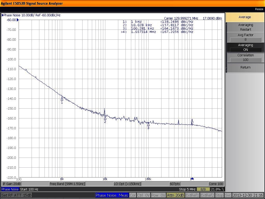
Output spectrum of K3
transceiver: spurious and the sideband noise of TX. Next task is filtration of the output IF signal in the crystal filter set. In the TX chain behind the transceiver (on transverter output, 0dBm level) is following set of 14MHz crystal units - with separate width for CW and SSB - see here, here. Cleansed spectrum passing through 15MHz LPF and GALI-6 MMIC to amplify the signal up to +10dBm to drive a mixer.
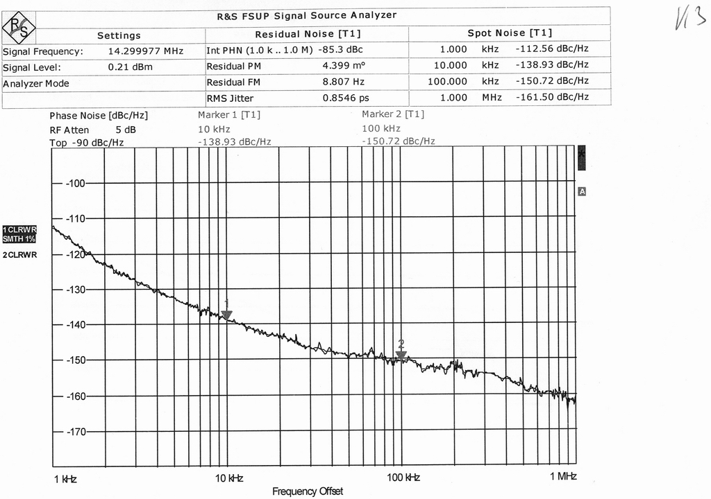
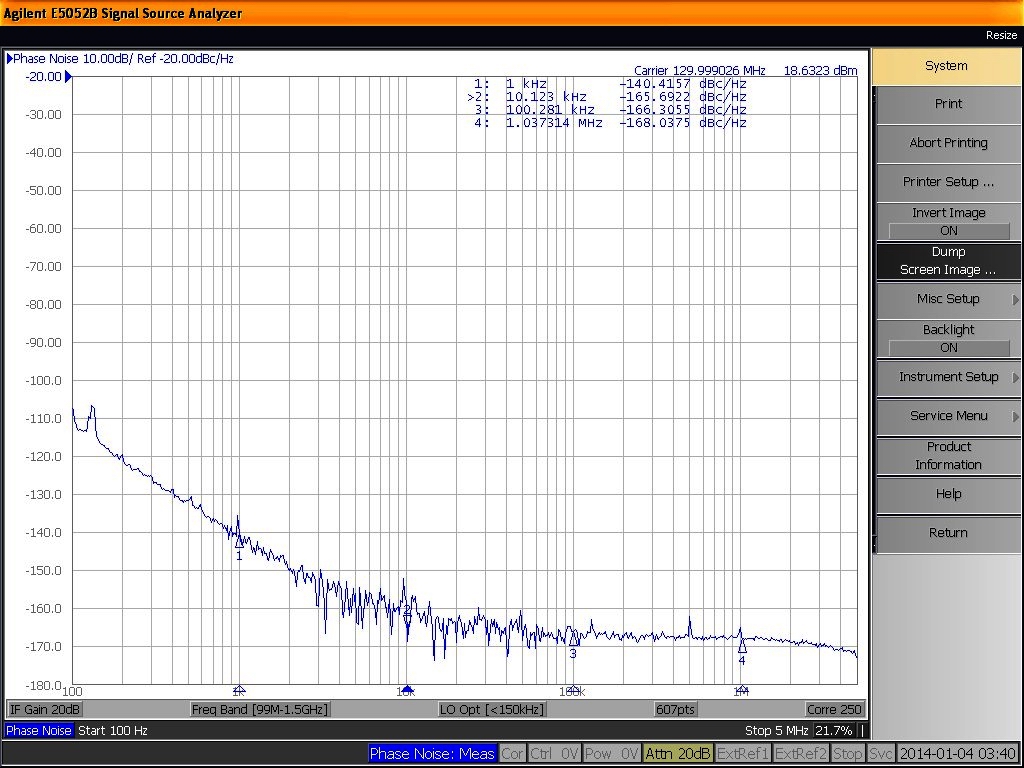
Pics: IF crystal filters board But before frequency conversion, very clean local oscillator (OCXO 130MHz) is needed to manage. Noise free oscillator is itself project for scientists. But life is too short and due to it OM3W designers used proven DC8RI oscillator with DL6NAA mods. Here was a first sample. On OK2KKW web we were focused to it two years ago, details you can read here. Compare measurment results of DC8RI's OCXO with average crystal and crystal unit, selected for best Q and noise:
Pics: DC8RI's OCXO
sideband noise with average crystal (left) and selected one (right)
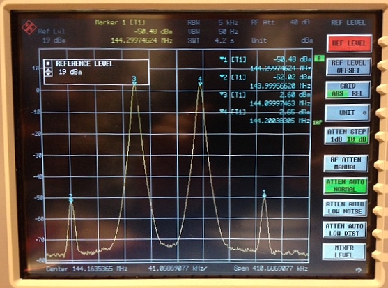
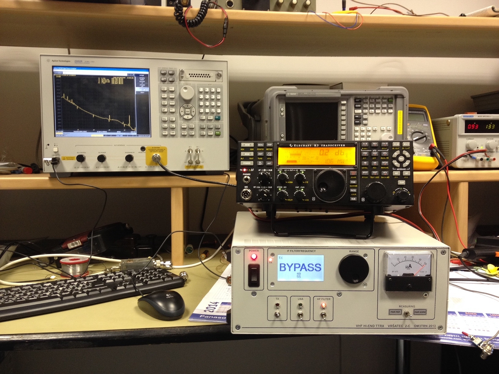
"this is a difference between our transverter and similar transverters of other producers...ordinary are used a bit lower robust mixers for TX (for example. ADE-1H) which are needed to drive lower IF level and in such case the complete transverter scarcely reach broadband noise level better, than -140 to -150 dBc/Hz even with use of IF crystal filters. We drive (switched to TX) HMJ5 with + 10 dBm level and in such case we can get the noise level on a quite better value....the following pics shows 2m out from mixer, driven by 2 x 10 dBm.....what is equivalent of single tone +16 dBm.....and intermodulations are still low. Even we could to increase an IF a little bit......"
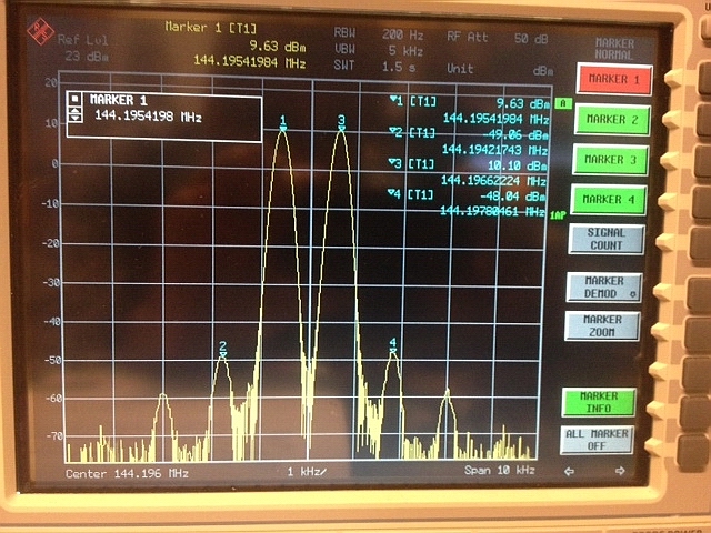
Pic: intermodulation spectrum on the RF port of HMJ5 mixer in case of two tones test with (2x) +10dBm IF level However, these mixers are not available and due to it the same mixer is used for both RX and TX. Switching circuits are necessary. Instead of diode (PIN) switch the circuit designer (OM3TRN) prefers max. dynamics and uses around mixer (but as well as between crystal filters) expensive low signal relays. OM1BM wrote: "..behind mixer is 3-resonators TOKO filter and after it PHA-1 MMIC amplifier. We have tested diplexer just behind the mixer, but it doesn't bring any performance improvement, so we finally omit it... behind MMIC is next 3 resonators BPF, not TOKO, but home made.... we needed lower attenuation (TOKO has 2,7 and the home made helical only about 1dB). Output of the second BPF on +16dBm level represent final TX output port of the transverter..." The info about omiting of diplexer (to prevent reflection of 116MHz mirror frequency back into mixer) is for me (OK1VPZ) surprise, but it show extraordinary HMJ5 mixer performance. Picture of intermodulations of transverter TX signal output on +16dBm PEP two tones test it convincingly proves.
Pic: intermodulations of two tones spectrum (2x10dBm, i.e. +16dBm PEP) on transverter output
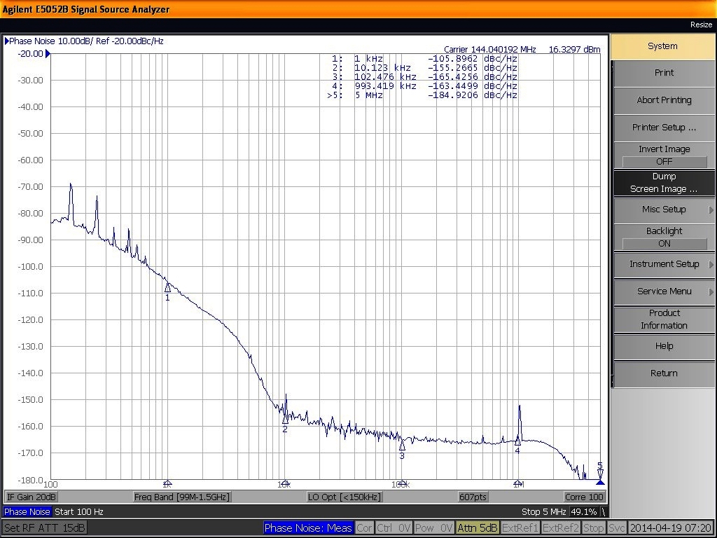
Pics: sideband noise on
transverter (driven by K3) output on +16dBm level. Left chart with
switched off
Pics: sideband noise on
transverter (driven by K3) output on +16dBm level. Left chart with
switched off And what about the next circuits of OM3W's transmitting chain? OM1BM responses: "behind the transverter we have the drivers box, where those +16dBm are splitted into 5 ways and each of these ways have separately adjustable attenuator 3 to 13 dB and behind it 5 pcs of RA60H1317 hybrids with LPF and output level monitoring. From each of these "badges" we get at max. 8W RF for drive of 4 SSPAs (MRFE6VP61K25H).........The output signal from driver look like this":
Pic: intermodulation spectrum on the output of one RA60H1317 driver in case of max. designed output power (8W PEP)
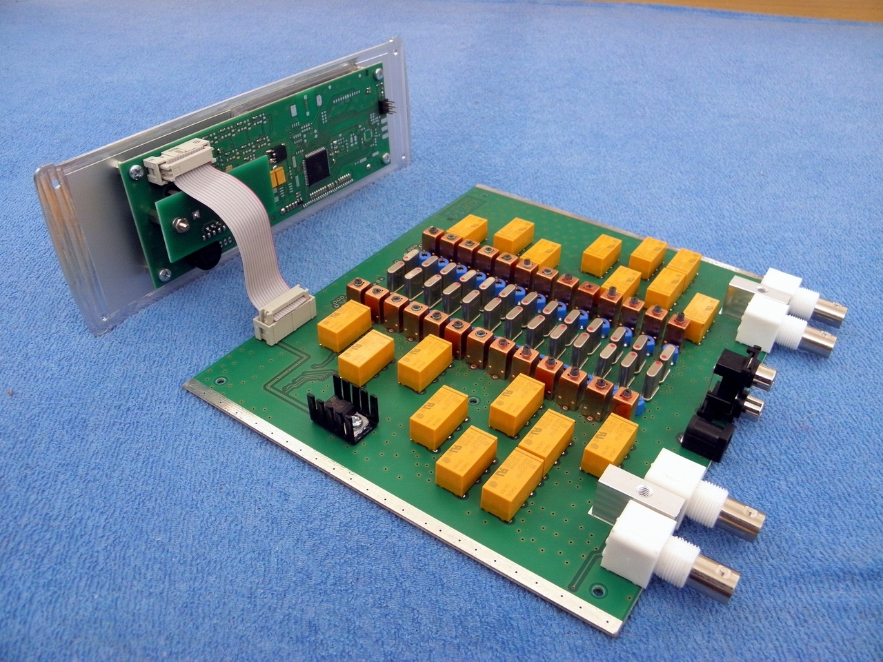
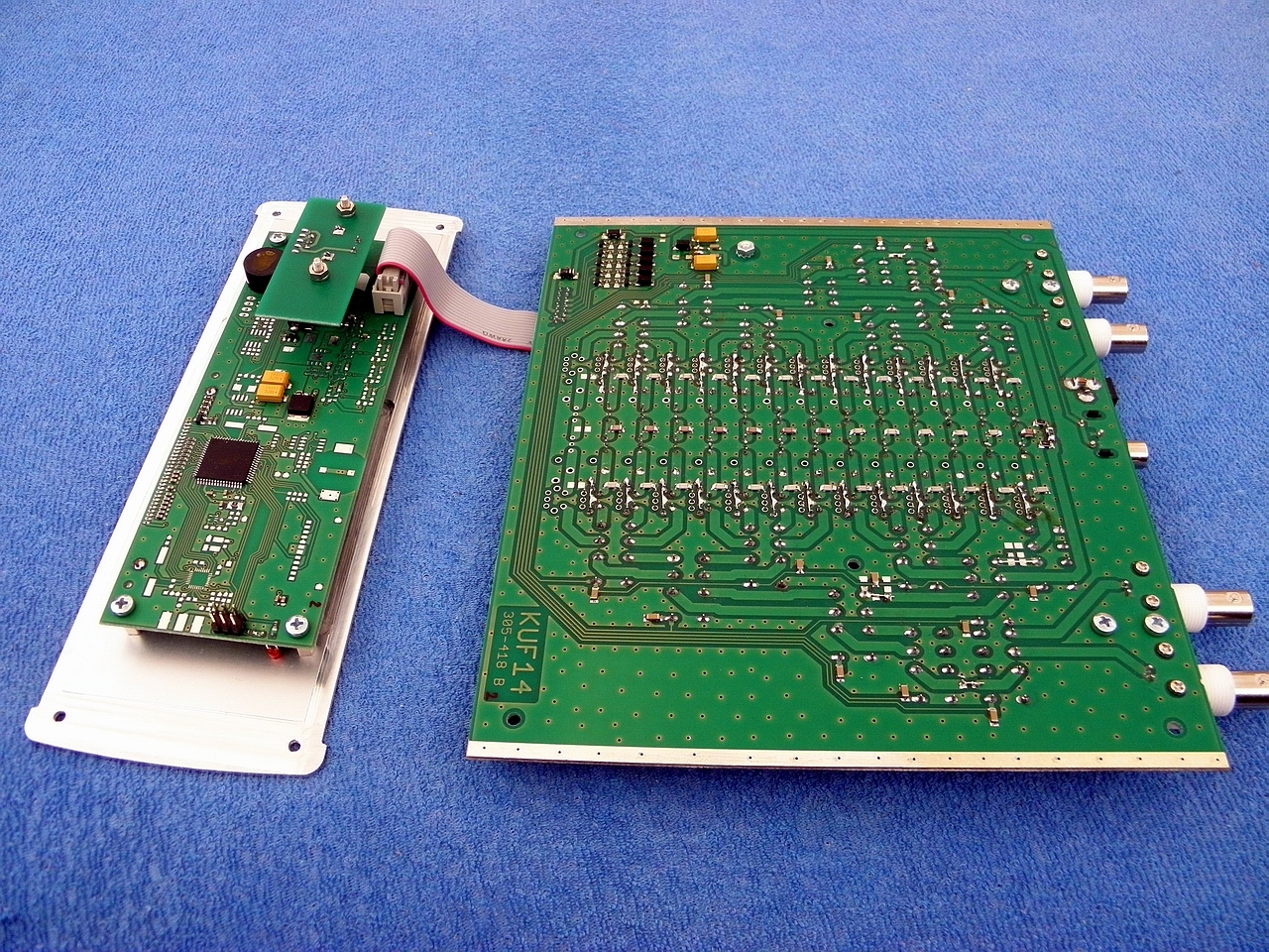
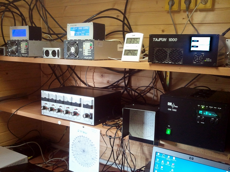
"This is a short summary, how it looks on the table..........transverter beside K3 consist of RX part, IF crystal filters board and TX part with +16dBm out. The next pic shows driver and all PAs. The driver has splitter, attenuators and 5 hybrid amplifiers ....."
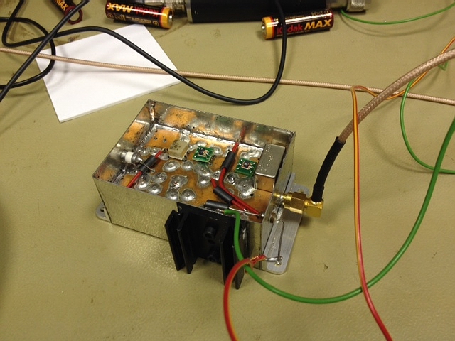
Pics: on left is the
transverter in time of construction, on right already in final status in
time of
measure
of output
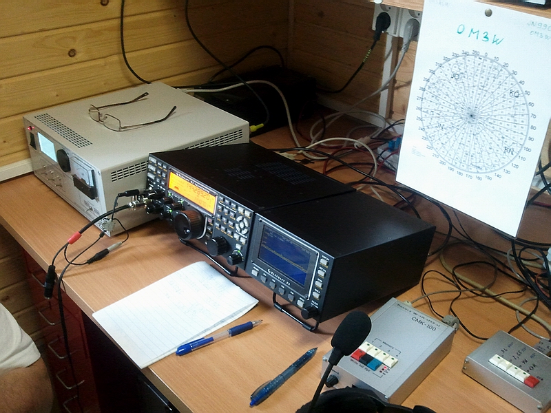
Pics:
complete setup of OM3W gear for VHF contest
- on left transverter and K3, right pics shows driver box with
"...and for final
we should say, that we didn't try to invent a wheel....only pickup other
designers ideas, everything what was freely published and by measuring
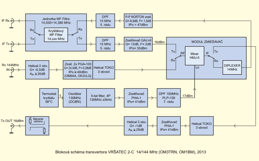
managed optimalized setup for K3." And conclusion: OM3W apparently at this time has (from the perspective of transmitting spectrum) the most clean signal on 144MHz across all former Czechoslovak area. Let me wish to all designers of this gear my acknowledgement for very good result a put my congratulation to them and - to all other OK and OM contest stations wish the same clean signal station on the opposite hill. And for final I would personally express thanks, that our old idea about improvement of sideband noise by use of crystal filters between transceiver and transverter (for commercial purpose produced lately by third party) were completed to the top fulfilment. Here is the block diagram of transverter unit:
|