|
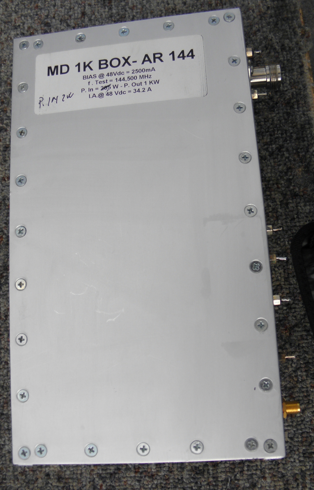
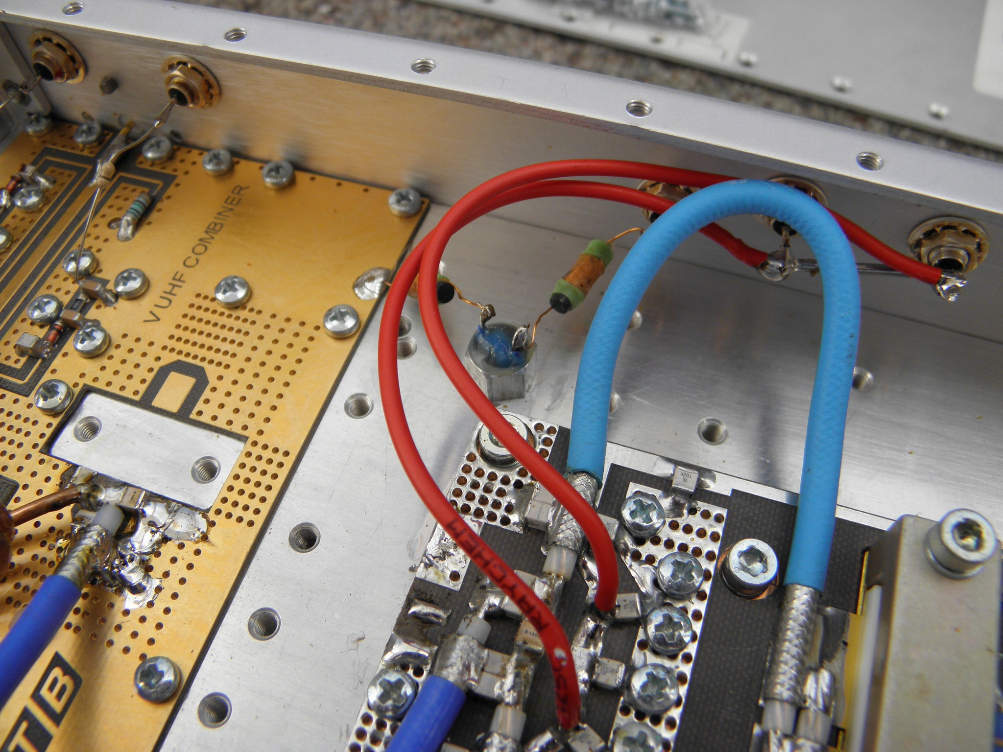
ITALAB 1kW 144MHz Power amplifier MD 1K Box - AR 144 How to connect a supporting circuits This PA module is produced by ITALAB s.a., Italy. See the web page of this amplifier here. However a year ago was for sale cheaper version without any control board. Because this module does not consist any of supporting circuits, i was asked by one friend, who bought it, to suggest schematic connection with use of my simple control modules for SSPA as were published here. Because this PA consist of popular MRFE6vp61k25h transistor, maybe it would be a bit helpful for others, who made similar PA. People, who have long time practice of SSPAs operation recommend to have at each PA at least these protection:
Together with these protections you must have some principal indication of operation status of SSPA. It request to have at least:
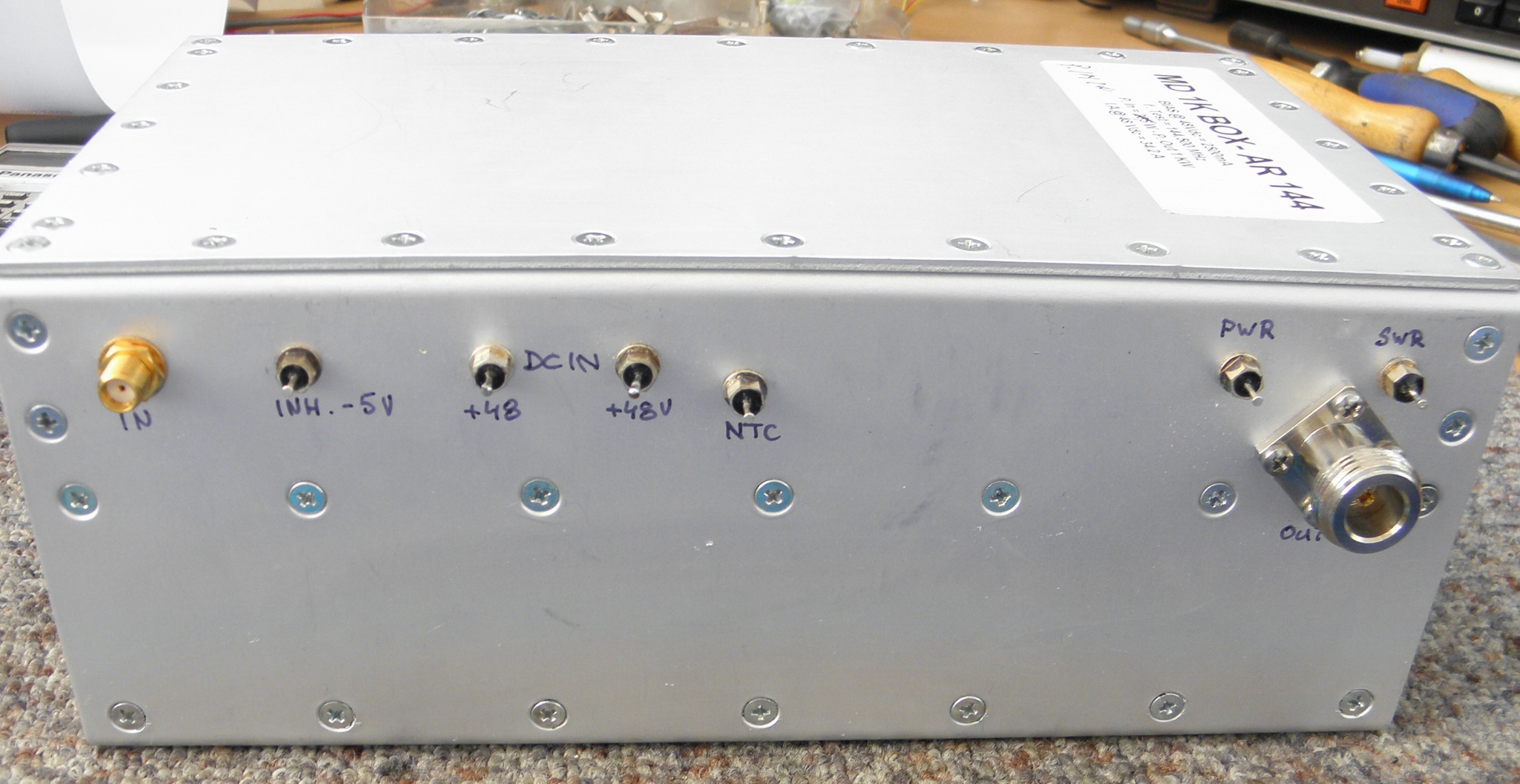
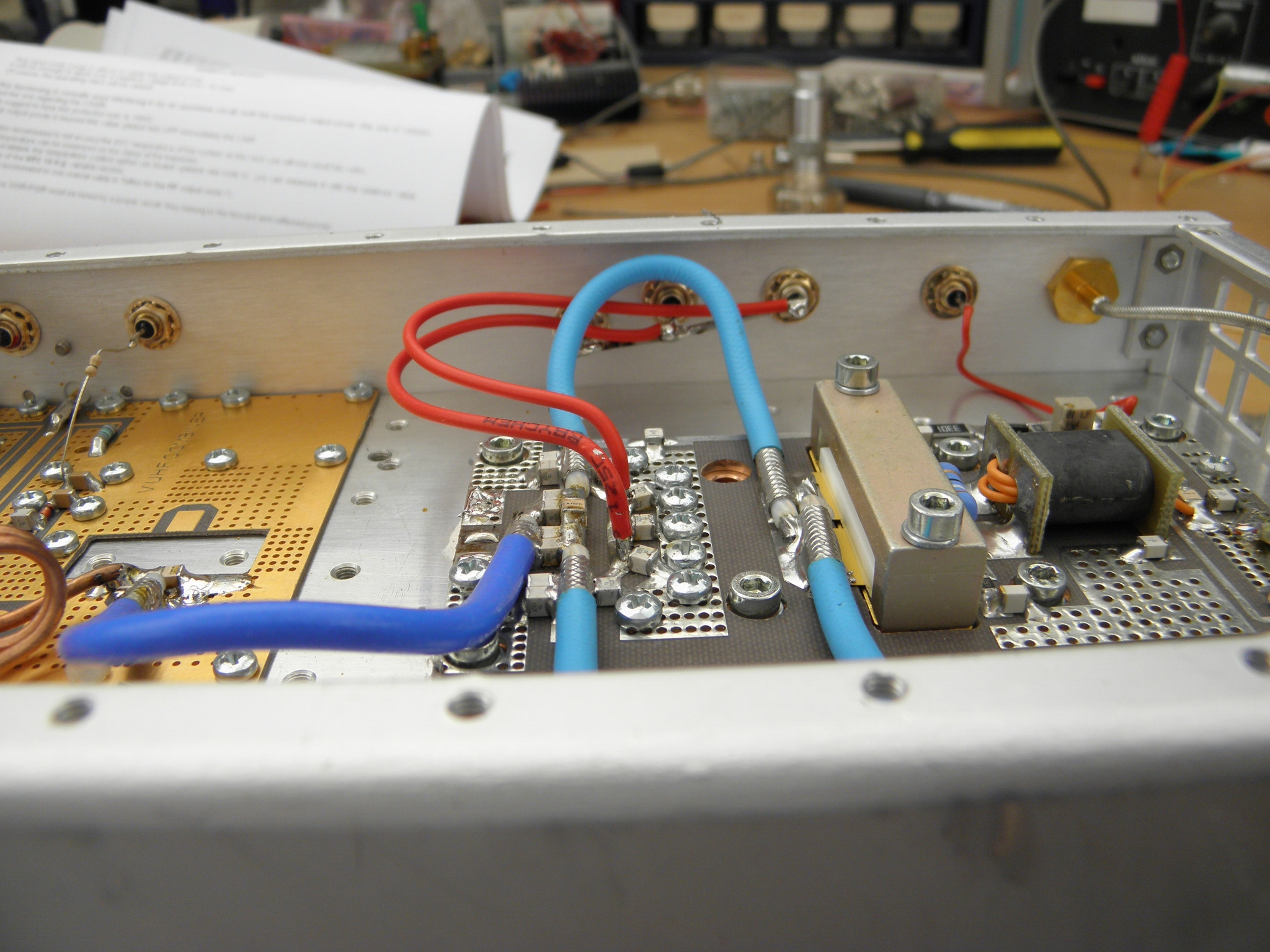
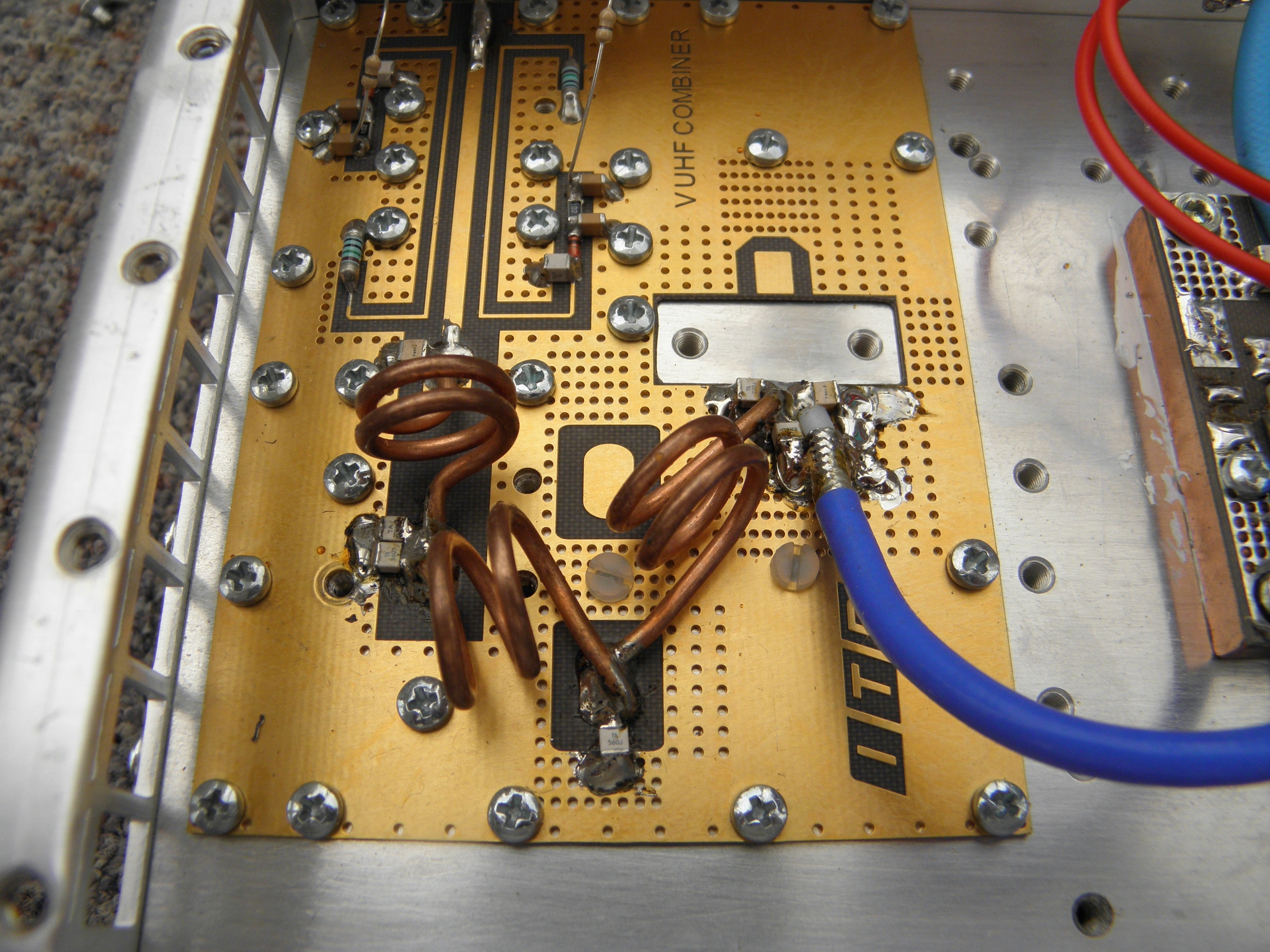
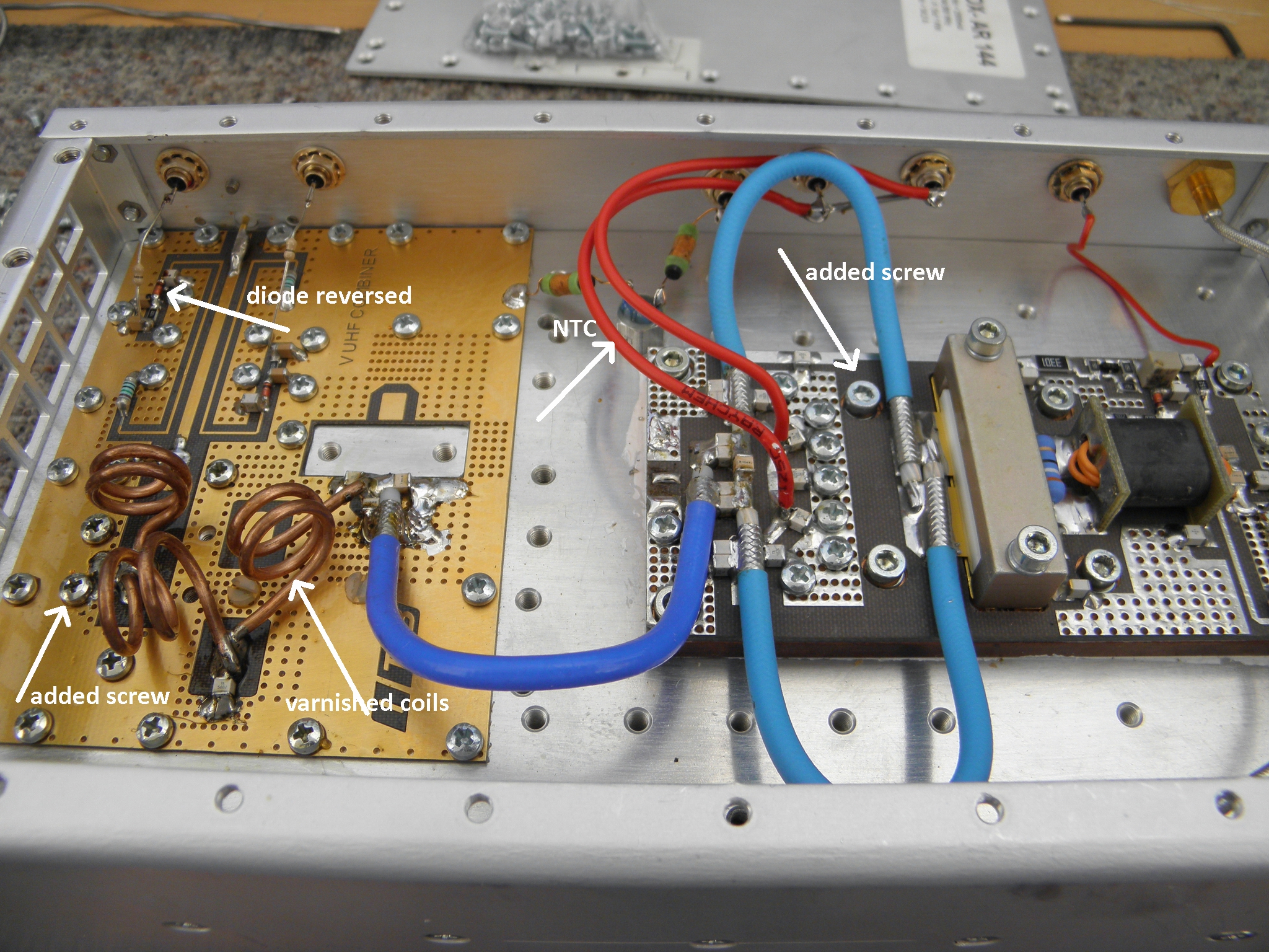
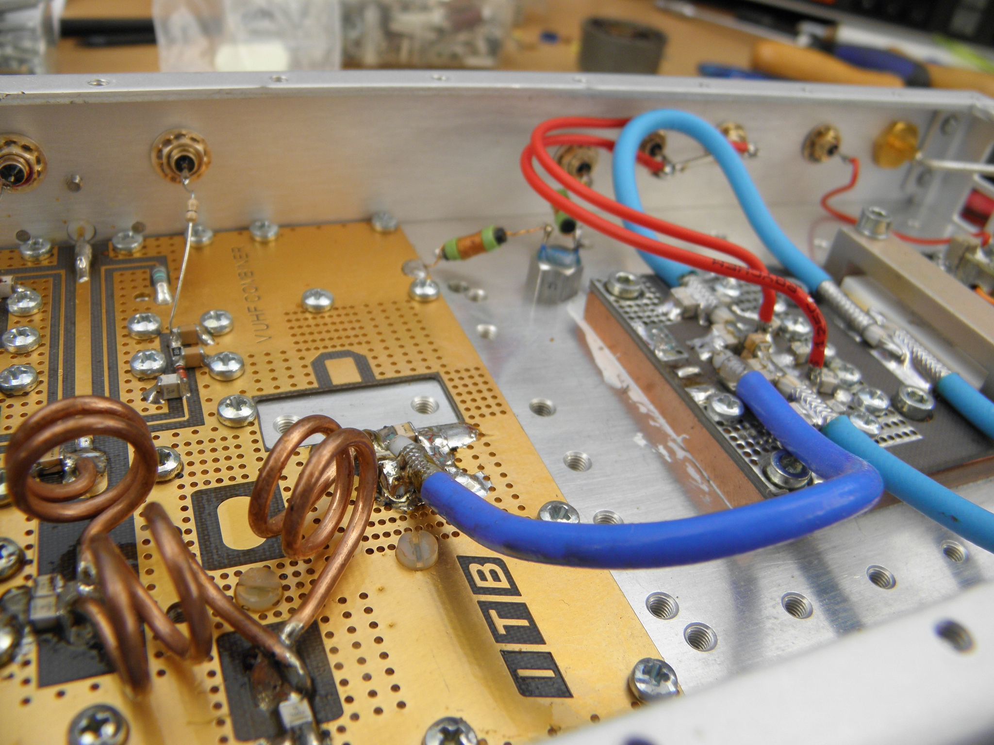
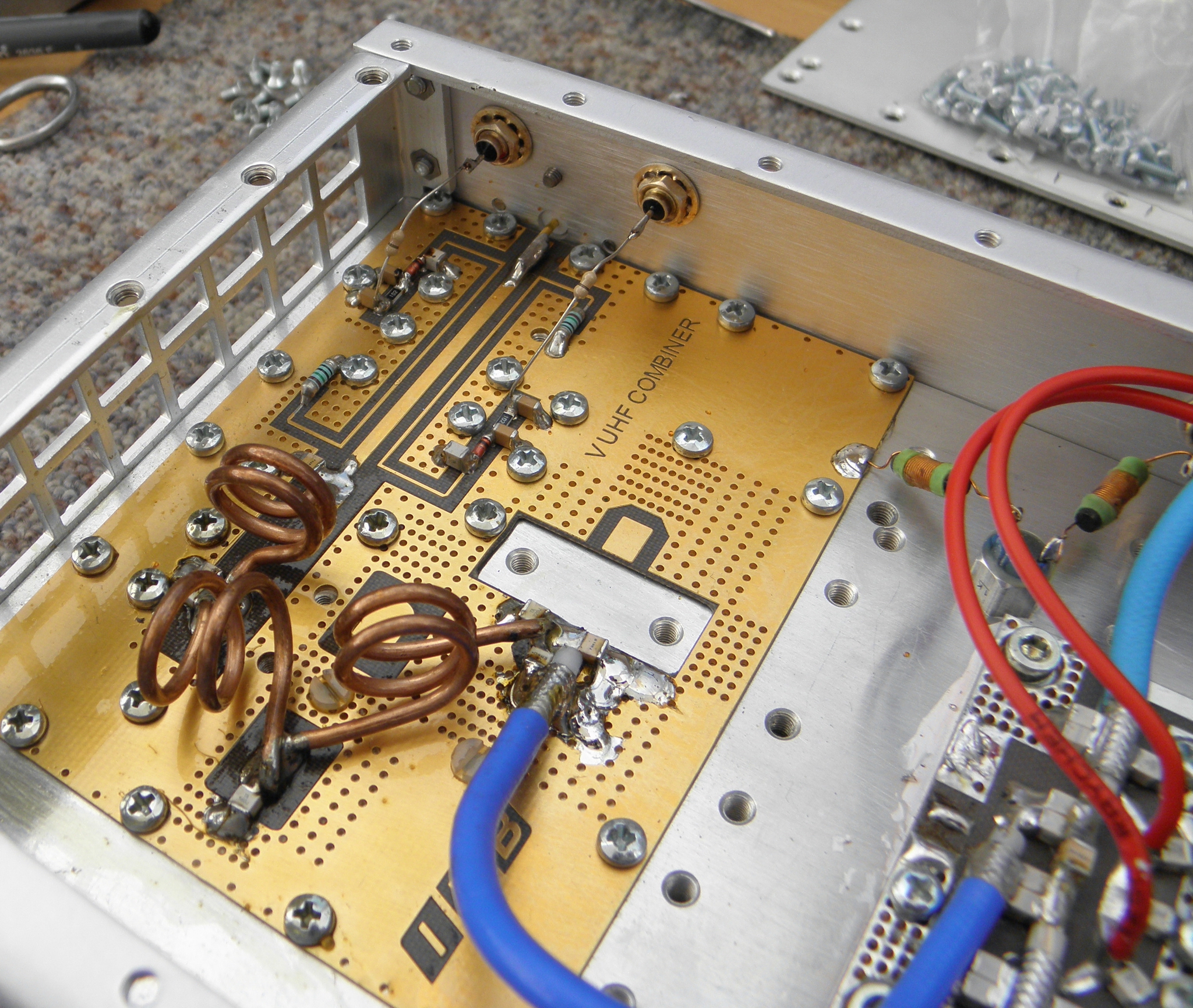
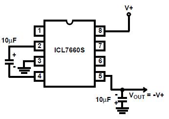
Beside it will be very usefull to have output reflection monitoring and temperature monitoring as well.. But let's return back to described ITALAB PA. The PAs from ITALAB have control input assigned as "Inhibit". This is unusual for amateur radio construction, where we are using ordinary positive voltage for BIAS circuits, but it is probably result of long years ITALAB experience with PAs for FM Radio broadcasting. Within reception is needed on the "Inhibit" pin insert minus 5V DC, what turn the BIAS of transistor to zero (to prevent noise addition into receiver chain). Such negative voltage you may generate from +5V DC stabilized voltage (in any case you will need in PA unit some separate power supply for control circuits, like antenna relay), ordinary by reduce of 12 or 24 V stabilized supply by LM7805 stabilizer. Negative voltage you can create easily by use of ICL7660 chip. The recommended connection is here. During transmitting you should keep the "inhibit" input of PA to ground by small relay . In case of use of PEP Wattmetter board you can advantegously use the negative supply on such board. The PA have within TX the BIAS abt. 2.8Amps from 48V stabilized high power supply. Note: the input BIAS circuit of ITALAB has no temp compensation and when the PA reach maximum allowed temperature (abt. 60 deg of Celsius), the BIAS may be increased even up to 7 Amps! It request very, very good cooling by powerfull fan, who will pass through the heatsink and as well as via transistor and LPF cavity plenty of cold air! Do not underestimate enough cooling! For protection and monitoring of supply current passing into SSPA you may use this circuit. Next two (or even three) pins are for PA powering. Exact 48V DC is recommended, the power supply unit should be able deliver up to 35 Amps (1700W)! In case of model with internal NTC, the third PA pin (feedthrough capacitor) is not connected to supply line, but to internal NTC. ITALAB recommends use 10k NTC, I had at home only 1k NTC, so I put it there with chokes (see picture). Such NTC guard max. temp limit of PA, which should not exceed 55°C. In such temp has 1k NTC (by EPCOS) resistance abt. 330R, in case of 10k NTC it would be abt. 2.7k. The PA in operation should never exceed the maximum temperature 60°C! Protection circuit in such case must break down the PTT of PA (include BIAS) when such temp is reached. As low the temp of PA transistor will be, the lifetime of PA will be longer! Comparator, which control the cooling fan and may disable PTT in case of too high temp you can find here and here. The limits you may adjust as well as by this way. Two pins close to the output N connector are PWR and SWR detectors outputs. Voltage on PWR is related to the power of course. In case of this ITALAB PA I measured 1.43 V DC @ 800W and 1.60V DC @ 1kW out. Because the internal impedance of PWR detector is above 1kiloohm, I would suggest to not connect here mechanical Deprez meter, but rather use an operational amplifier to secure high input impedance for more precise measurment. Then will be posible to use square root scale of power measurment. PEP wattmeter (link above) is good alternative and for SSB operation the PEP meter is highly recommended and could be even combined with protection circuit to prevent overloading of PA. SWR PIN should be connected to the input of protection circuit, which ensure blocking of PTT in case of too high reverse power. You may use simple comparator as shown here. For use of such circuit the detector diode in a SWR directional coupler must be reversed to create negative voltage. Simple draft of SWR protection unit with fixed resistors for the above mentioned ITALAB PA is here. At last, but not least, the next important circuit of each PA is a time sequencer. You can use this one, or any other - however: do not use sequencer, where the timing is provided by delay of more relays (such sequencer is not stable and reliable) and take care in case of use microrocessor based sequencer due to possible interference from RF field, because it may have negative impact to free running of microprocessor software. And refuse at all the solution using the central station sequencer, which controls more units by CINCH connectors - such installation is unreliable (connectors, RF influence, connection mistakes). Each PA should have installed sequencer inside of PA box to prevent connectors bad contacts, RF field influence and human errors. The above mentioned ITALAB PA you may use for example by the following way:
I hope it may help someone a bit. Best 73 by OK1VPZ
Measurment results (on this sample) of PA: RF in for RF
out 1kW.............................. 3,4W Conclusion: this PA is (due to intermodulations) suitable for VHF contesting, if the PEP power from the PA will be below 800 - 900W out (max). OK1VPZ |