|
It's well known, that penetration of SSPA is growing between ham radio operators - particularly on UHF and SHF bands. However, if you want to use SSPA in practice safely, notably in the contest operation, you need to operate such PA either very tamely, or the unit must be very well secured by relevant protections. The very basic protection is watching of temperature of power transistor, because with higher temp the maximum allowed output power of any solid state PWR elements is falling rapidly down.The next fundamental protection is SWR protection as well as watching of maximum supply current for each PWR element. When bipolar transistor is utilized, the next necessary circuit is good BIAS circuit. On the OK2KKW web were already published more of such circuits (look here, here, here, here, here and here). These circuits should send to the control unit of SSPA at least two messages - the first level is a warning, which give to operator an info that some circuit already reached operation limit, what for example will switch the cooling fan to maximum speed, or push operator (by loud, or optical alarm) to decrease output power or interrupt operation for some time. The second level of alarm mean: monitored device already reached the critical level, which can damage the PA - so in this moment the PA must be blocked to protect from destruction... Blocking of PA is in our meaning the status, when the PA is not possible turn on to the PWR TX status (ordinarily by keeping of PWR transistors in the status of deep C class) - but such blocking MUST NOT block as well as switching of the antenna relay into TX status, because in the case of parallel operation of more PAs in the multibeaming mode, the crosstalk between antennas may damage LNA or RX, just connected to the blocked PA! Alarm outputs (reaching of critical value) of these protection circuits must PA not only raise alarm and immediately block the TXing, but it should hold the PA down for longer time to push the operator to modify his behaviour, it mean the PA should be blocked for at least 20 seconds, beside other reasons to protect PA against oscillation. Such delay and alarming can be realized by simple microchip circuit and it is not matter of this article and design of such is simple (maybe in the near future I will describe some simple control circuit with static CMOS ICs). For final of this foreword I need underline necessity of proper time sequencer for control of PA and antenna relay, which should be installed always directly inside of each PA - very common solution with external sequencer, which controls "stupid" PA (PAs) and the antenna relay (relays) is in the VHF Contests practise always much worse, than use of "smartly sequenced PA" with sequencer inside, because external sequencer, interconnected with other units by number of wires and connectors will earlier or later damage at least LNAs or even PA due to some failed connection.. And it's why I would always suggest to have a sequencer in each PA - for example this one. Let's leave large forword now and focuse our interest to the till now missing construction of monitoring and protection of the SSPA supply DC current. For sure it will be useful to repeat basic demands for such unit:
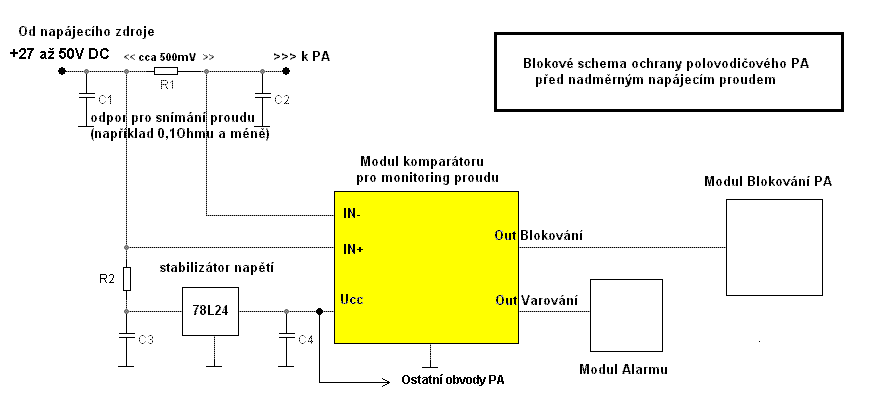
Solution of the above: Connection schematics of protection unit:
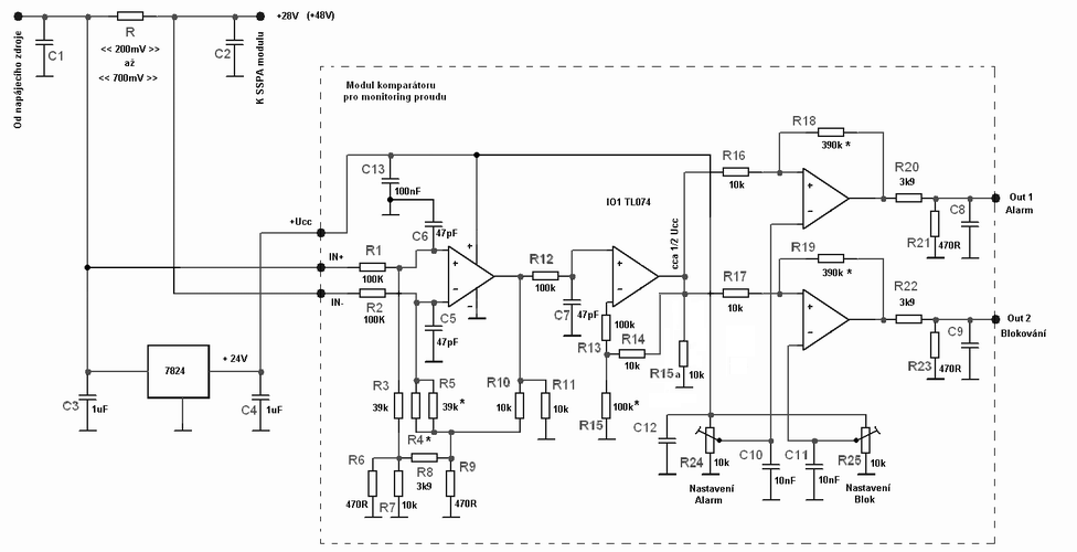
The voltage drop on the "power line" sensor resistor, connected to PA module would be for 28 to 52V supply abt. 0,8V, for 13.8V supply cca 0.3V. As a current sensor resistor must be used element with low thermal drift with value about 0,1 Ohm and even less. For the sensor resistor use piece of constantan wire, or use resistors, produced for such sensors, ordinarily in the TO220 package - i.e. here. Logic outputs from security unit are by resistors adapted for 5V CMOS levels. In case of 9V supply of the unit, or another logic level these resistors (R21&23) should be adjusted. The stabilized supply (24V) should be within any mode of PA operation very stable, because the monitoring unit has no additional internal stabilization for powering of comparators. The protection unit schematics is here:
On the input of circuit are two voltage dividers by R1 + R3 a R2 + R4/R5 resistors, with precision better than 1%. These dividers allows to monitor voltage drop on the sensor resistor, operated on much higher voltage, than is supply of operational amplifiers. R4 (220k) is not used, this position can be utilized for adjustment of voltage dividers and in a prictise it is not needed. The input comparison amplifier has gain about 10. In case of zero current through the sensor will be on the output of first amplifier about 1,3V, because used "few cents" TL074 IC is not "rail to rail" type. Buffer amplifier has gain close to 1, however in case of higher gain demand (but for the best result the voltage on the output of the buffer amplifier in the case of max. supply current through the sensor resistor, should be about 50-60% of stabilized voltage) you can increase gain by lowering of R15 value. The output two comparators are ordinary, setup of the limits is better adjust by resistor trimmers trimry R24 a R25. Value of R18 and R19 define hysteresis of comparators. In the designed case is abt. 5%, if the value of these resistors will be higher, hysteresis will be lower. In this circuit is nothing treacherous and in case of correct setup will works with no troubles. In case of more PA PWR modules, such protection should be used for each of them.
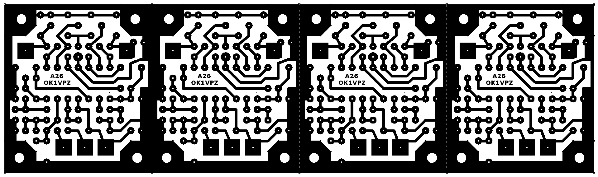
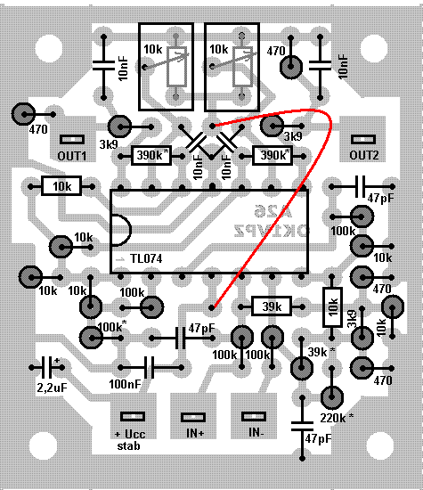
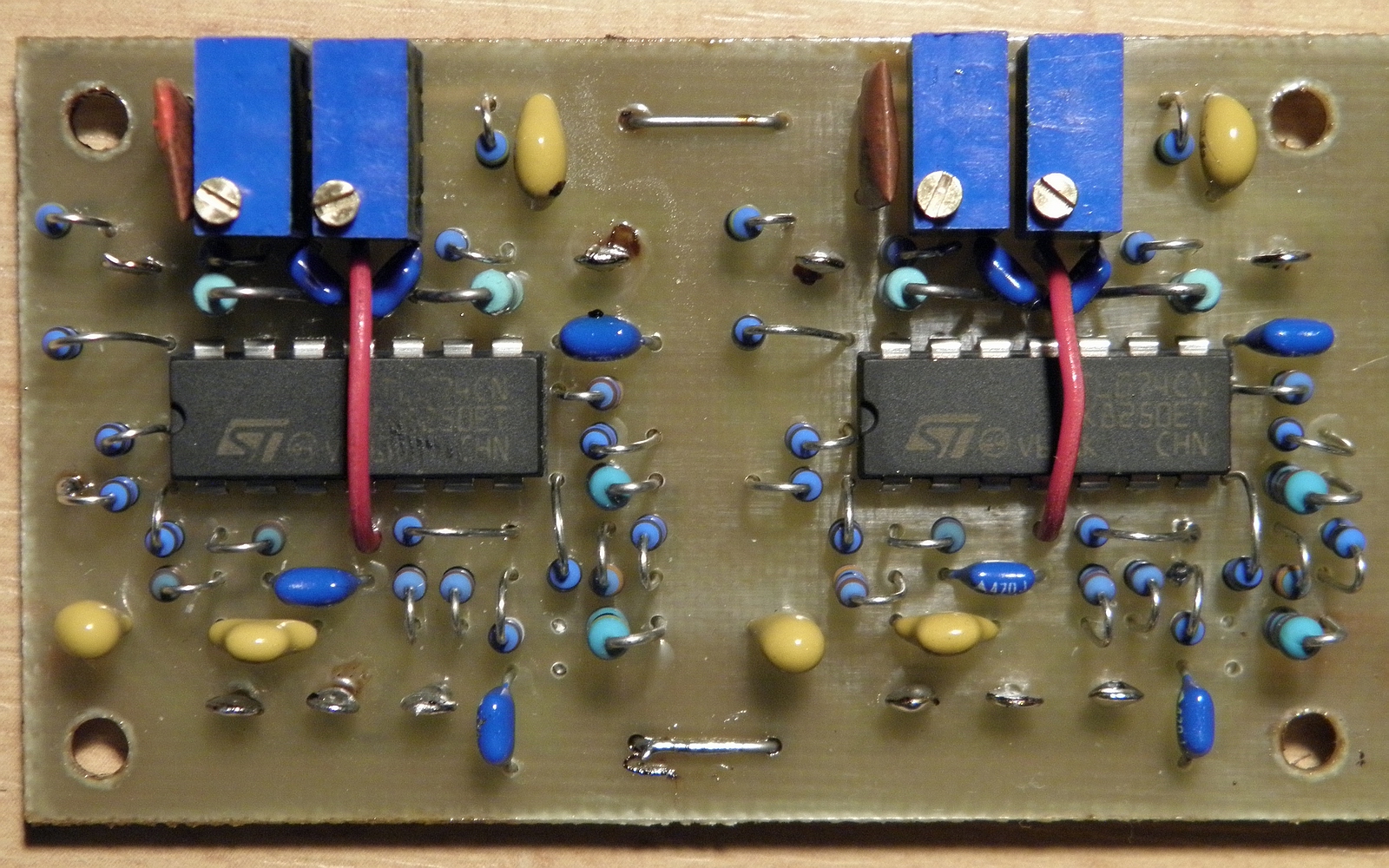
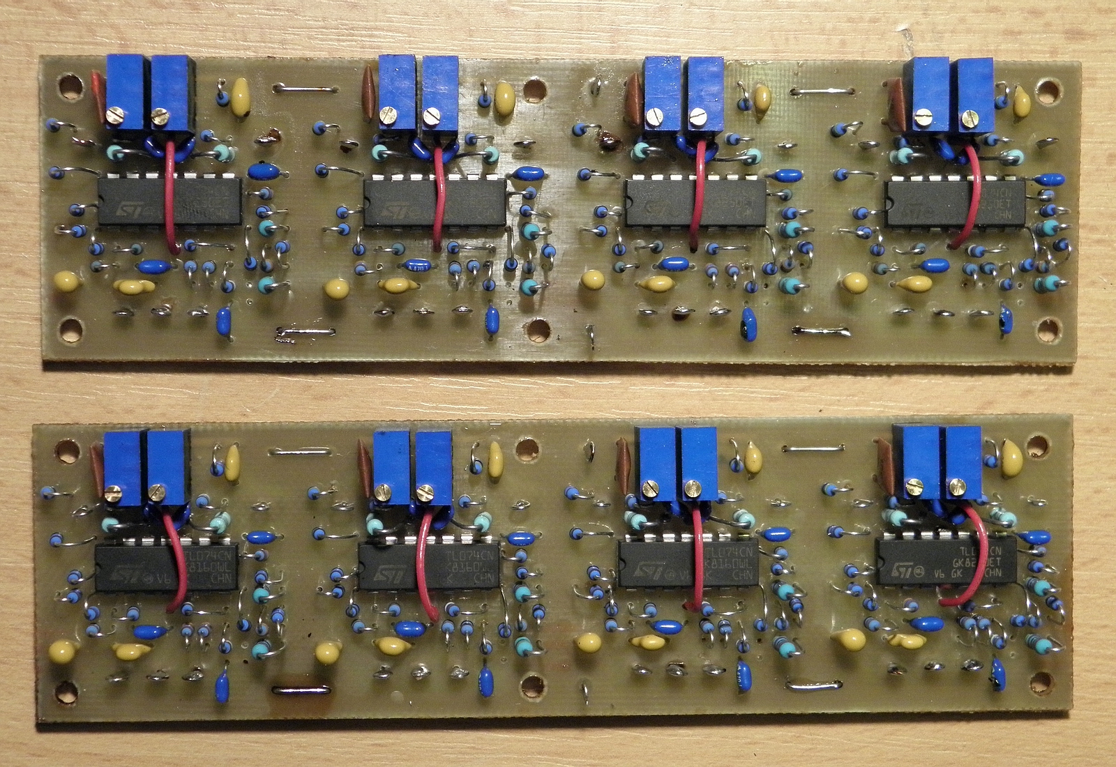
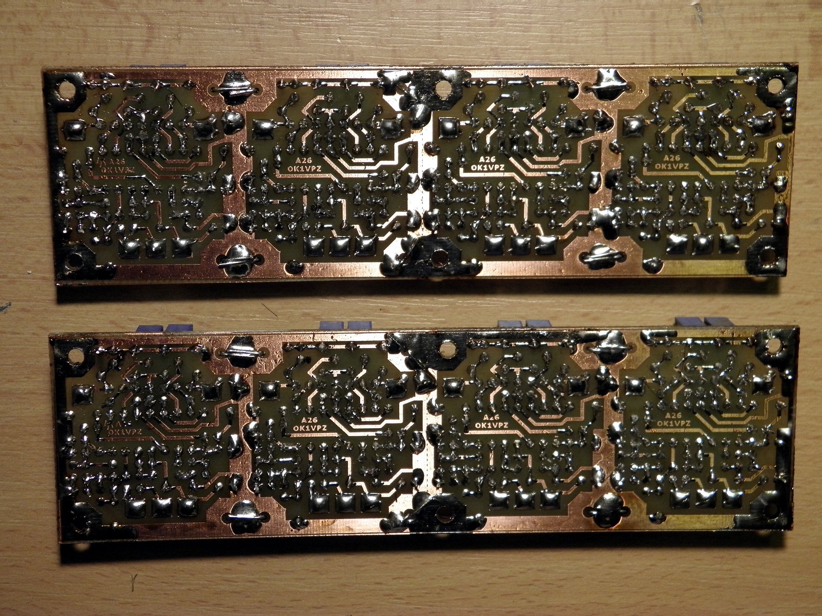
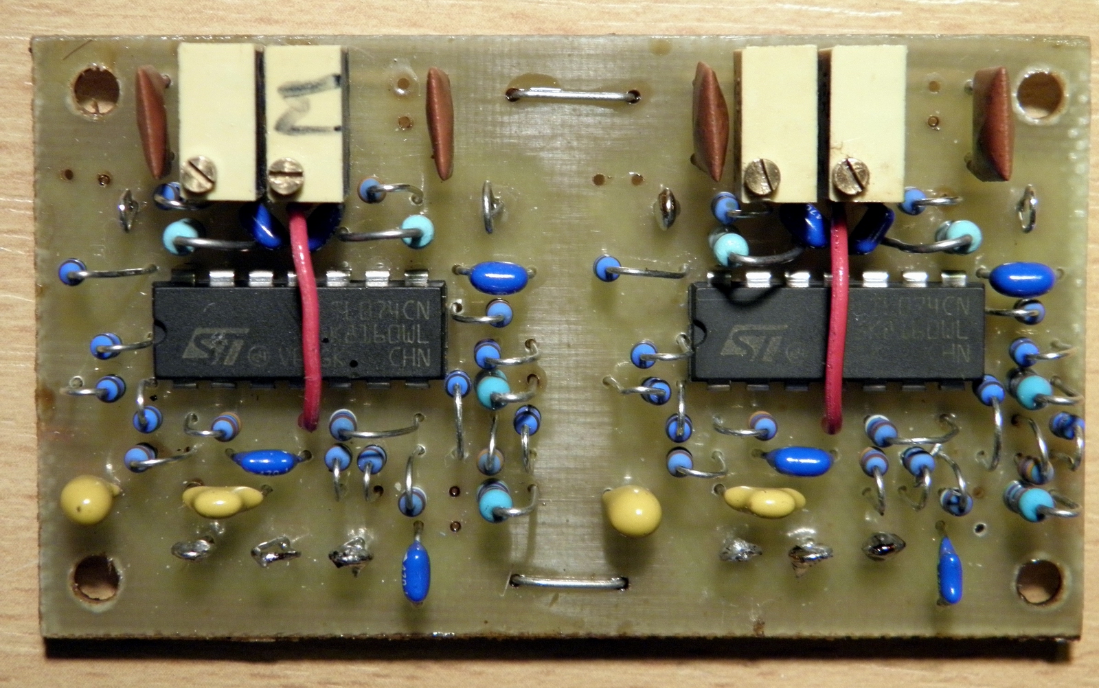
The protection unit is realized on the standard one sided epoxy PCB 35 x 40mm size (one unit - so the below, quadruple PCB will be long 140mm). The PCB has been designed for 70cm SSPA and has one wire interconnection. The PCB can be purchased here for price similar to other designs. Ask for OK1VPZ A26 board. For home made production the PCB drawing is here:
When somebody will prefer SMD elements, the size can be of course much smaller. However due to my age I prefer standard elements and here is the results:
73 de OK1VPZ Few pics:
|