|
I've got a notice, that my construction notes, published in our OK2KKW HW Corner, are often well-known and repeating them again is not needed. However„ the devil is in the detail“ and I believe, that publishing of my faults could be useful to someone to avoid repeating the same mistakes. That's why I wrote these articles in such a way that they repeat hundreds of known truths. I consider amateur construction experiments as a part similar to (or it should be so) perceiving QSL as a part of a DX QSO. But back to the point: In the reports from the last two tropo contests (1,2) I promised to write a few words about our new 70cm solid state PA. It's actually not a new PA, it's just rebuilt UHF TV PA. Let me say a few words on this subject: I was a bit involved in the radio-communication branch of TV transmitters some years ago and I would like to say that solid state RF amplifiers of different manufacturers used to broadcast analogue TV in UHF bands are in fact similar. Therefore, although the following talk is focused on rebuilding one particular PA module, I think these experiences are also useful when you try to convert other UHF PA units for amateur usage in the 70cm band. Why? In the 70s and 80s of the 20th century UHF TV transmitters were mainly based on tubes as klystrons, triodes and tetrodes (initially with separated FM PA for sound carriers, later also for common power amplification of analogue picture and sound). The upcoming of commercial TV broadcasting and the need of coverage of smaller regions with local transmitters started the usage of transistor PAs with output up to several kWs grouped from individual modules of about 100 to 200 watts at the turn of the 80's and 90's. In the 90s the bipolar transistors optimized for the low level inter-modulations, of course, were used for this purpose. LDMOS power transistors appeared in these TV transmitters at the end of the century. Termination of analogue terrestrial TV broadcasting (and transition to DVB-T and to DTT in general) in Europe, USA, Canada, Australia, and other advanced countries led to the situation that these former analogue TV SSPA modules became obsolete and available for radio amateurs as electronic waste at very low price. This, of course, brought an interest in their possible use in applications like EME or terrestrial ham radio traffic. F5DQK did a very good job by writing of some articles about different UHF TV PA conversion on his web. A couple of his articles (with the courtesy of F5DQK) are available here as well. However, by far, not all of these UHF TV PA conversion attempts have been successful in amateur radio practice, and thus tube PAs are still widely used in ham radio shacks so far. However, these tube PAs have one principal disadvantage: they are not very suitable for digital EME operation in the FSK mode because the anode circuits of these PAs (with the exception for liquid cooled PAs) tend to overheat, resulting in detuning of anode circuits, reduction of efficiency and it even may result in destruction of the tube. Last but not least, this is related to the fact that CW traffic is mistakenly perceived by radio amateurs as telegraph traffic, although it is a Continuous Carrier expression, where PAs are permanently exposed to high load. One of the effective solutions of these thermal problems in the commercial TV operation was using of solid state PAs. With the delay of about 25 years we see that the requirements that had led to the replacement of large UHF TV tube PAs by solid state PAs are the same in the radio amateur practice. The transistors can be directly mounted onto a heat-sink that has a zero voltage potential and can be formed according to the need, including water cooling. The heat capacity of such heat-sink is large, the solid state PA circuits work with low impedance and therefore are usually fairly broadband, so there is no problem of detuning and thermal efficiency drift On the other hand the drawback of solid state PAs is that RF power transistors have to operate at a much lower temperature than the tubes. This leads to a problem of thermal resistance between the heat-sink and the cooling medium (usually air) because the temperature gradient between the heat-sink and the coolant medium is much lower. This problem is underestimated in ham radio designs quite often and that leads to negative reputation of solid state PAs among radio amateurs. Many blown SSPAs cause that life expectancy is reported lower than that of PA with tubes. This may be true for amateur constructions particularly if the power amplifiers are not sufficiently cooled and especially for amateur designers of such power amplifiers. It is worthwhile to realize an old wisdom for RF power transistors: "With temperature increasing by 10° C, the reliability deteriorate about 100 times." Due to this fact, the solid state RF power transistors shall be:
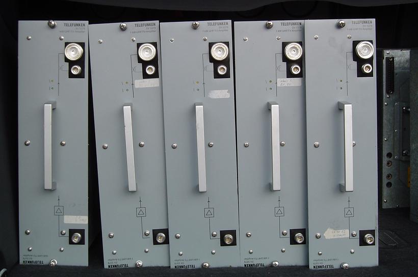
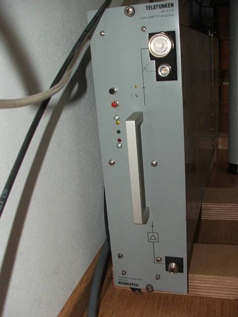
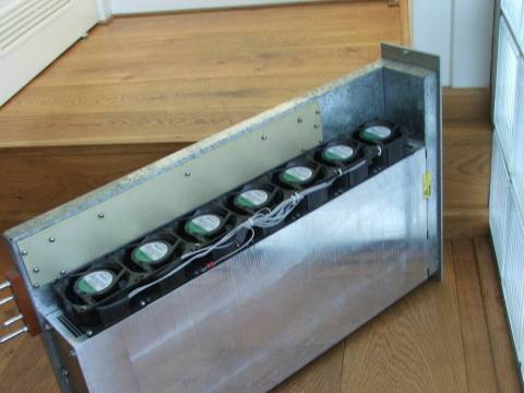
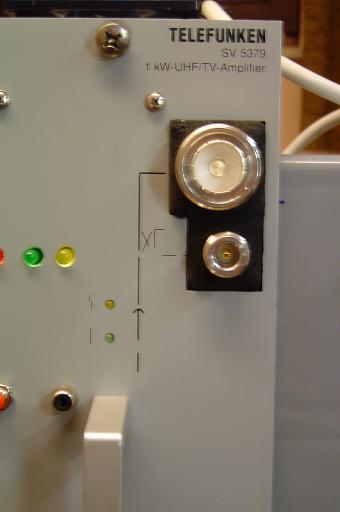
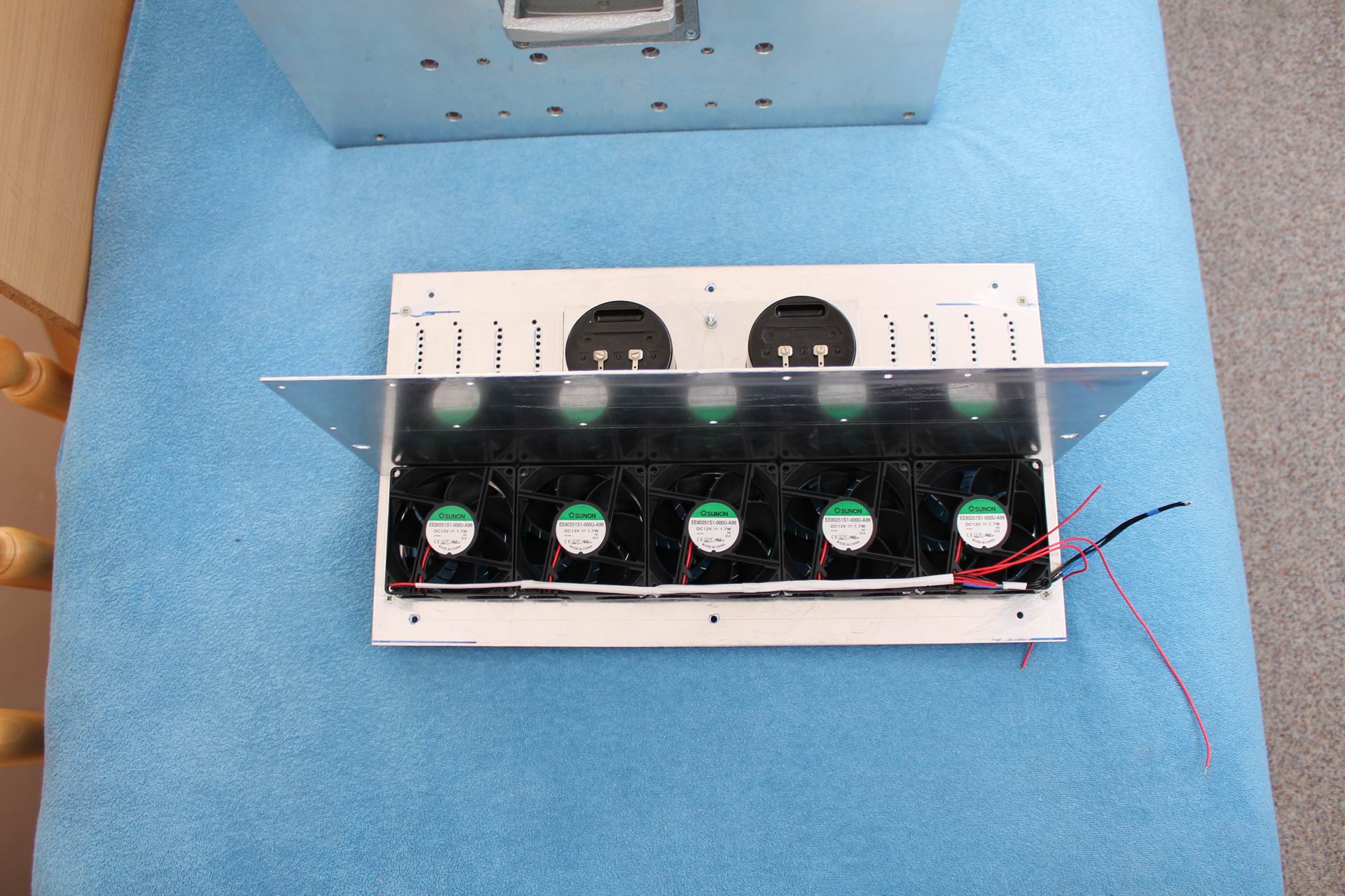
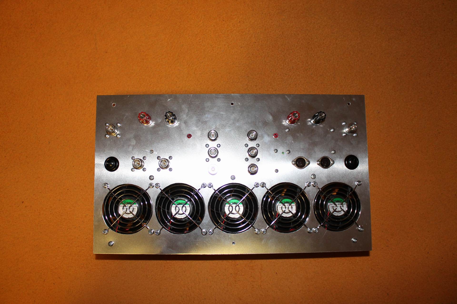
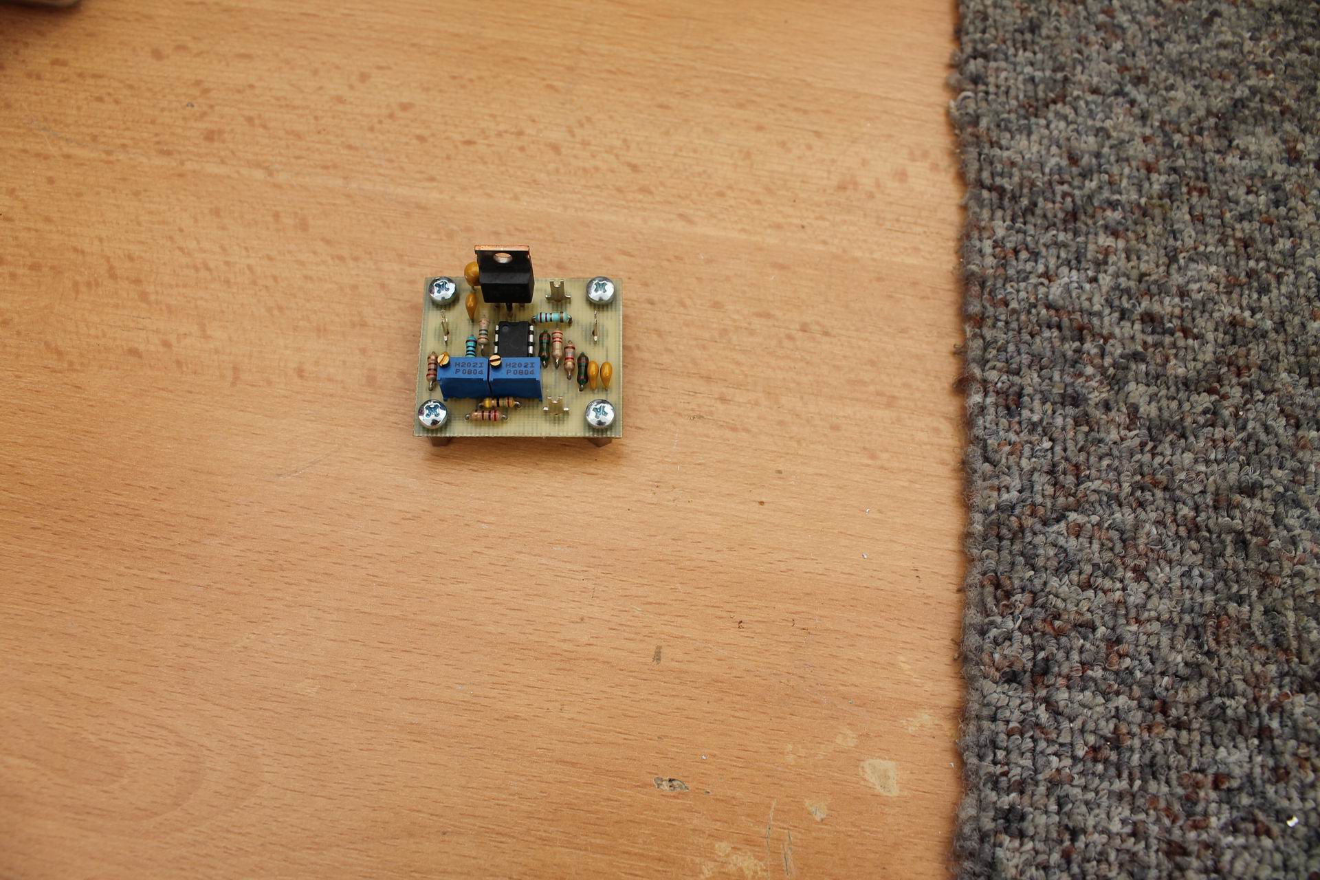
This implies that the temperature of the RF power solid state elements must be monitored closely and if the temperature grows too high the PA should be switched off immediately by a protection circuit to avoid damage of the solid state modules! The same applies for the monitoring of the reflected power from the load back to the amplifier! Sudden high SWR can be caused not only by the antenna but also by failure in connectors or in coaxial relay. Therefore there also should be the monitoring of the balancing of the PA modules so as the individual modules deliver the same output power and none of them gets overheated. Other kinds of protection are individual depending on the PA design. Most of them are usually implemented in a smart switched power supply. Perhaps the overcurrent protection for the individual modules may make sense not only as overload protection but also as a short circuit protection. In transistor PAs like this we are working with a voltage of tens of volts and tens of amperes so it would be very unfortunate if a breakdown in a PA caused an electric arc burning in the power transistor. These transistors are still using beryllium ceramic mats and the smoke of beryllium oxide, if scattered, is very toxic. Therefore, the power circuits must be designed not only to prevent the permitted currents from being exceeded, but also to block the power supply before we have a solid state PA welding machine. Which transistors? As mentioned above, we mostly see power modules fitted with bipolar transistors in the UHF TV PAs of the 90s. I don't want to generalize, but LDMOS transistors are used in TV PA since the turn of the century, at least based on my experience with manufacturers of this technology (e.g. Rohde Schwarz, Motorola, NEC, Telefunken, SAGEM, ERICSSON, Italian manufacturers and Czech Tesla). Most of the transistors are TPV8100, BLV861, BLV862 and later then LDMOS BLF861A, 2SK2396A etc. A couple of transistors data are here: 1, 2, 3, 4, 5, 6. From what I could see, probably the most common are TPV8100B and BLV861 (they are equivalents to certain level). The advantage of these PAs is modular concept where individual PA modules can be removed from the PA, replaced, repaired and eventually adapted to our needs. These modules also include bias current circuitry, which is especially important for keeping bipolar transistors in linear regime (see also the circuit here). Fortunately, these PA modules are designed to transmit analogue TV signal with common video and audio amplification, so their intermodulation 3rd order products have to be suppressed quite well. This is also the case with the source of the bias current, which usually does not have to be fundamentally modified. What performance can we expect? As the demand for suppression of intermodulation products is not as high for amateur radio use as for analogue TV radio amateur designers usually believe that the PA is capable of delivering more power than the manufacturer shows for TV traffic but there is a hidden problem which proves this opinion wrong. The analogue TV with its negative modulation and suppressed carrier is actually the impulse modulation from the power point view, because the full power is delivered only in the line synchronization pulse, while it is about half (depending on the instant brightness) at the time of active line transmission (i.e. transmission of the luminance component of the image). It means that the PA is actually running in some kind of impulse operation. It gives the maximum power only about 1/10 of the time, while in 90% of the time the power is at most 70% of the maximum (full black image). The TV PA design and its cooling correspond to this mode. If we constantly load the PA by 100% of maximum power without changing the design, the transistor chip gets overheated and the transistor will not survive for a long time ... It is therefore necessary to verify whether the cooling of UHF TV PA and individual transistors is sufficient for the amateur usage and estimate how much of the CW („key down“) signal we can afford to pull out from from this PA. It should be said that in practice it will be less than the PEP value (sync. pulses) in TV traffic because the cooling of the transistor is not only determined by the heat-sink size but first of all by the heat transition through the thermal resistance between the transistor chip and the heat-sink! In other words, the limiting performance of solid state PAs that have undergone conversions from UHF TV PA to radio amateur use in the 70cm band is not determined by the suppression of intermodulation products but rather by cooling. For the transistor TPV8100B, the thermal resistance between the chip and the transverse contact surface is about 0.8° C/W and the allowed chip temperature is max. 200 ° C. However, if we want to achieve reliable operation with a certain margin, we should not work with the chip temperature higher than 150 ° C (especially for CW operation). With 100W transistors output (single device) and 50% efficiency 100W of thermal power has to be conducted from the chip, which causes the thermal gradient of 80° C on the thermal resistance inside the transistor case. Under this condition the temperature of the transistor case reaches 70° C. Another thermal resistance is between the transistor contact surface and the heat-sink. According to the data sheet BLV861 (the same case) it is 0.2°C /W, i.e. further 20°C. In other words, the temperature of the heat-sink below (near beside) the transistor should be about 50° C. But we are not done, yet. Manufacturers indicate limitations of power losses at a higher chip temperature on power transistors. For the transistor above, the datasheet requests 1.25W/°C. It means if the nominal maximum power loss is at 25°C (215W), at the housing temperature of 70° C it will be: 215 - (70-25) * 1.25 = 158W. Fortunately, as mentioned above, we need to conduct from the chip in operation "only" about 100W, so the limit 158W won't be exceeded. Furthermore you need to take a look at the radiator manufacturer catalog, what is the thermal resistance of the radiator we want to use with cooling air temperature of approx. 30° C. If you do not know this value, you can measure it, or at least simply verify that the heat sink meets your expectations. This can be done by screwing the 100W terminating resistors 50R at the transistor place and supply them 100W (as for the TPV8100B configuration above) and wait until the heat-sink temperature has stabilized. Of course the heat-sink should be cooled the same way as in the PA operation. What will be the result? Will the radiator temperature be lower or higher than the above requested 50° C? If it is more, the heat-sink is insufficient. However, this is a primitive test of an available heat-sink. But what if there isn't a suitable original heat sink? The experience shows that heat-sinks suitable for this purpose are those with long narrow ribs (for example, 4 or more centimeters long and only about 1 to 2 mm thick) i.e. heat-sinks designed for forced draft cooling. See for example the Fischer Catalog (DL). When designing you should measure the heat-sink material performance. If you have another ready-made heat-sink you intend to use you have to simulate all heat sources (i.e. all modules) on the heat-sink used in the PA. If you have just the raw heat-sink material cut the piece of corresponding to one module and measure. The limiting factor for the radiator choice is also a question of the type of the air flow through the PA heat-sink. Experts (not including me) say that the better cooling can be achieved with laminar than turbulent air flow between the heat-sink ribs. This is the point we can ask ourselves how to blow. The original UHF TV PAs are usually cooled by a common turbine and several PA modules from one source of pressurized air. Since we do not have TV transmitter rack with air conditioning, we need to think of what can be realistic to achieve. Ordinary DC axial fans are well available in all sizes, but if they are not special types designed for high performance (but these are quite noisy and expensive), they often do not put enough pressure to blow along the entire length of the cooling ribs. If they are to blow into a space where there is some aerodynamic pressure, they begin to tear streamlines on their blades and their efficiency deteriorate rapidly. Instead of the acquisition of powerful and so noisy fans it is better to have two cheap axial fans on both sides of the cooling ribs. Suction at the outlet of the radiator reduces the turbulent flowing and the air inlet fan pushes the air into the space with lower pressure and so the cooling is more efficient then. My previous 70cm SSPA and its later (yet unfinished) 23cm kW variant is an example. Another important factor for choosing a radiator is its material. The thermal conductivity of aluminum is limited. Copper heat-sink is much better but also more expensive and heavier. But I wanted to build a portable PA so aluminum was the only choice. Simple enlargement of the aluminum heat-sink does not have much effect. The thickness of its base, which should be at least 10 to 15 mm, is much more important. Besides the power transistor (transceivers of the TV module) should be placed on a separate metal substrate with good thermal conductivity, preferably copper. That is the "spreader" of the heat sink, which improves the lower thermal conductivity of the aluminum. I was lucky with the TV PA Telefunken reconstruction (see below) that the heat-sink of the original PA was quite sufficient. But: These are general rules resulting from the theory and only practice shows if we have neglected against theory. Therefore let us return to the previous recommendation on how to test the cooling capacity of an available heat-sink: you will undoubtedly conclude that the recommended testing of a heat-sink is poor and not exact with regard to the aforementioned CW operating conditions and you will be right to some extent. For the EME traffic (WSJT), PA should be able to withstand a "just" 50 seconds of broadcasting and 70 seconds of reception i.e. not "key down" traffic. The full power rating for EME is not 100%, but less than 50%... but: Can you really guarantee that the cooling air temperature will be always equal to or less during the real traffic than in the test? Can you guarantee that the operator always switches off the PA after 50 seconds? Can you guarantee that the power distribution between individual transistors is always perfect? Probably not. So saving on cooling really does not pay off! I therefore recommend to design the PA for "key down" operation! After all, as mentioned above the transistors are not placed directly on the radiator, but within the amplifier module which also has its thermal characteristics. The pads under the UHF TV PA transistors are not always made of copper. The series of TV transmitters using the TPV8100B transistors is composed of the Motorola RFA8180B modules with aluminum washers on the module body. There may be other materials and/or transistors used in various types of UHF TV PA modules, but it will basically be similar. So any reserve is good! But there are more traps: the thermal resistance between the transistor contact surface and the heat spreader, which actually forms the mechanical pad of the amplifier module. We have encountered a problem with the TV PA Telefunken (SV 5379) that the transistors have been mounted in the body of the amplifier module (spreader) completely dry, that is, without greasing with the heat conducting silicone paste which results of course in higher thermal resistance. It was therefore necessary to carefully dismount the transistors from the PCB and apply a drop of the heat conducting paste to the bearing surface. But be careful, not all the heat-conducting pastes are the same. Consider there is a 100W heat which must flow through the surface of about 1cm2 with negligible losses. Therefore, Grizzly paste was used in layer as thin as possible. In order to obtain the lowest thermal resistance it is necessary to use the thinnest layer of the compound which only fills the scratches of the transistor and the bearing surfaces. Therefore I mixed the heat conducting paste with nitro thinner and put only a drop fitting at the tip of a screwdriver on the surface (which confirms the saying: the less, the more)! Of course, these recommendations apply generally to the design of any power RF amplifier, that is, also to modern high power LDMOS transistors, although they are usually directly soldered on the copper pad, but this article deals with the conversion of UHF TV PA for radio amateur use. However if you want to have realy reliable gear, your design should not exceed in operation any component data sheet limit. Remind - this PA conversion is not a commercial job. Let’s go back to this topic. After these considerations, I returned to practical work. A few years ago, we bought two of already mentioned 1KW UHF TV Telefunken from PA3CMC, and the boys from our club were pushing me a lot asking when I was going to do something about the hardware. For a long time I was thinking about leaving the PA basically in the original state like PE1RDP did.
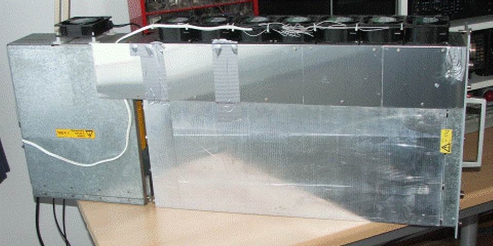
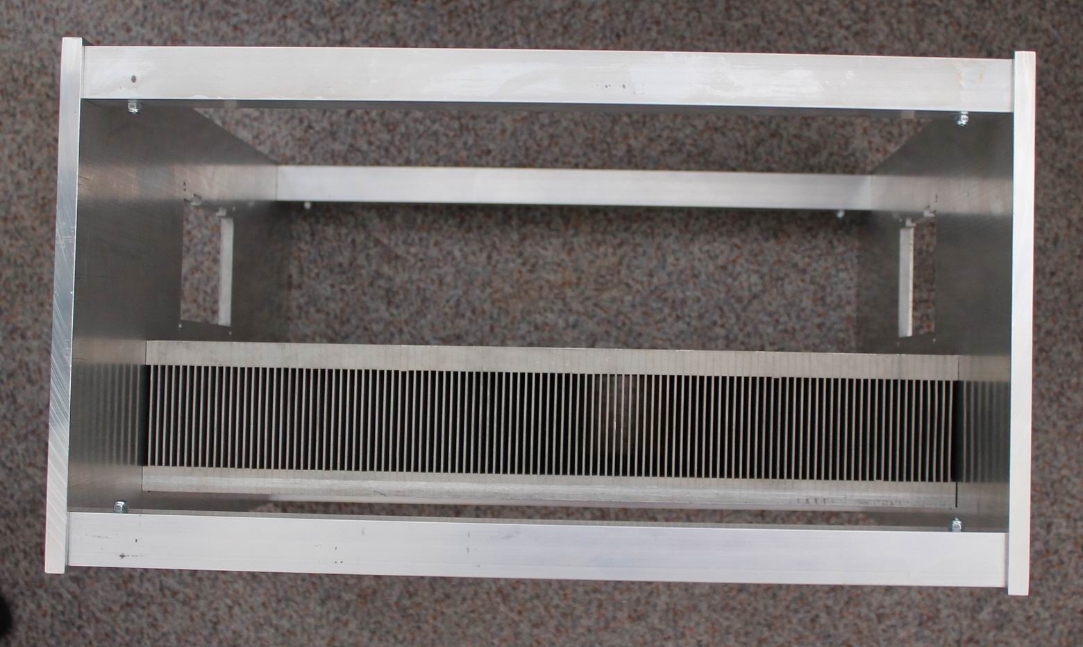
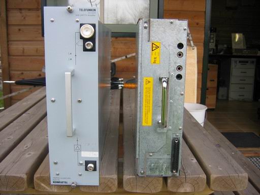
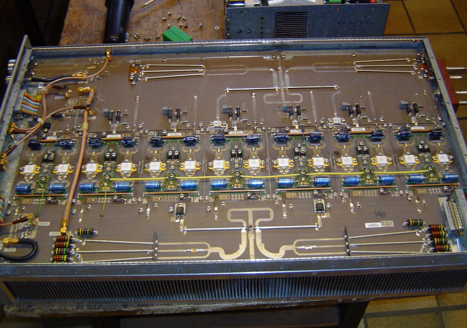
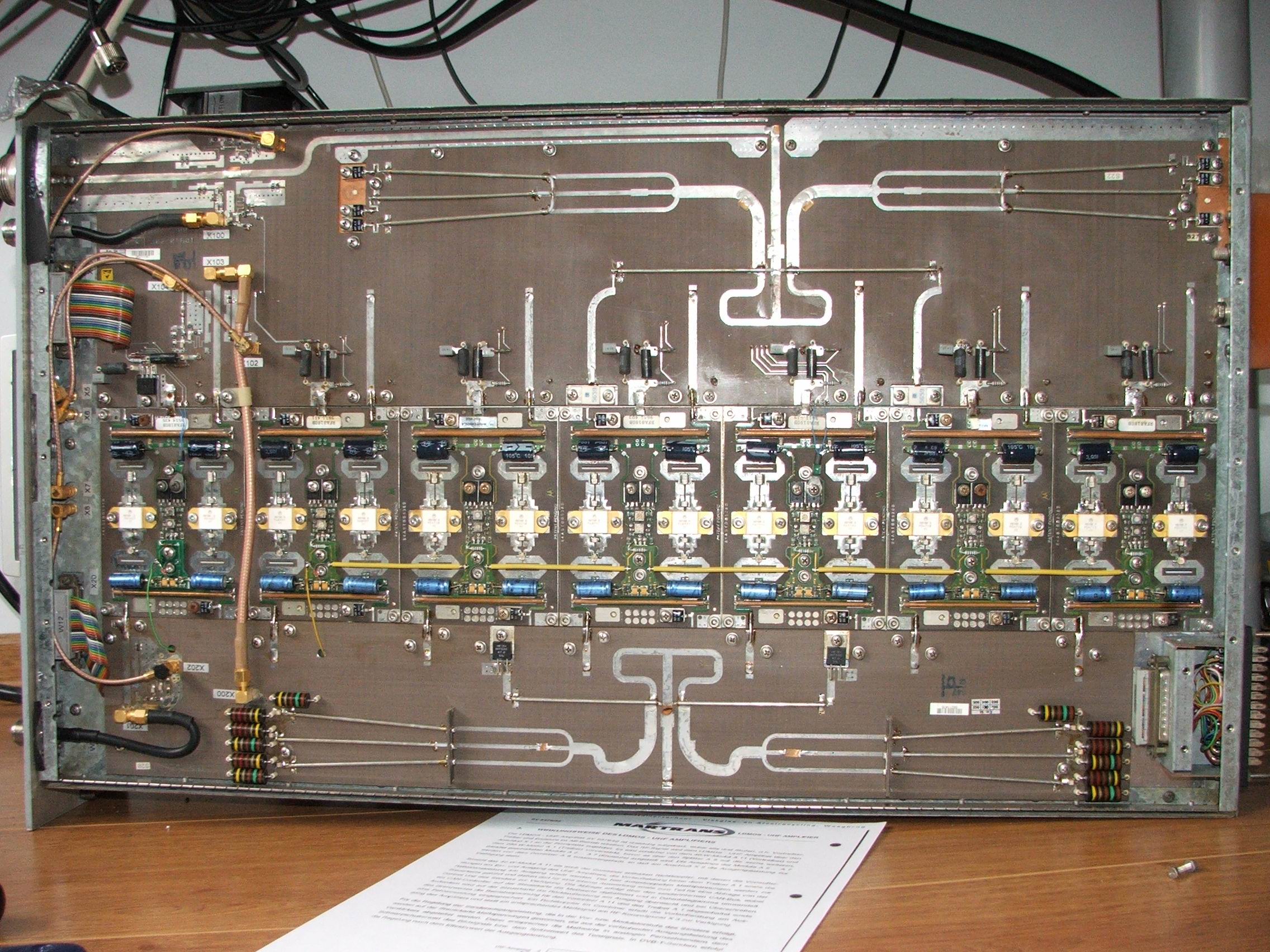
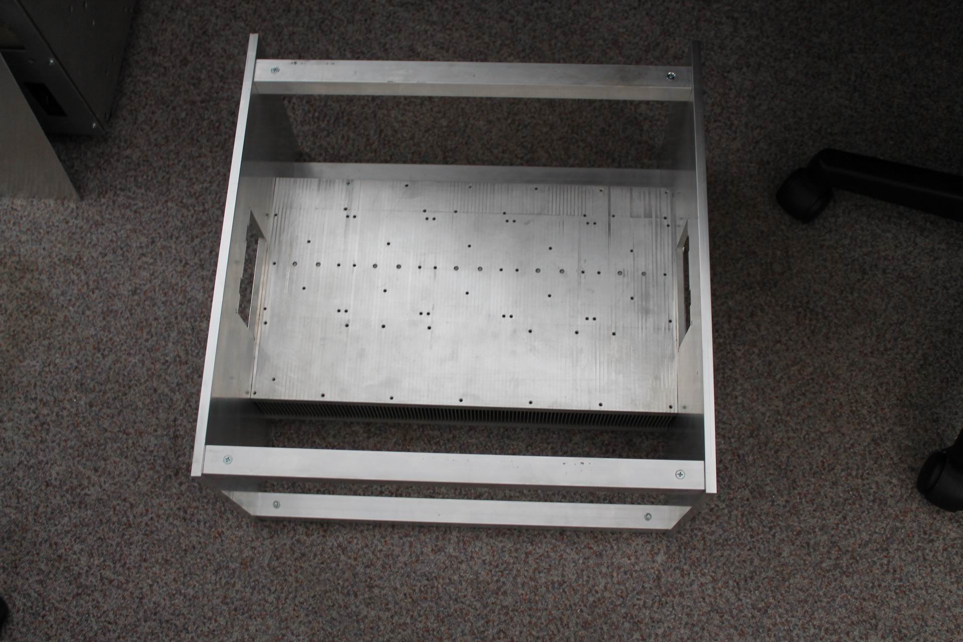
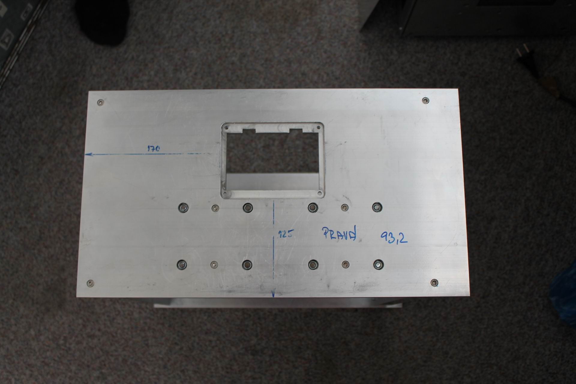
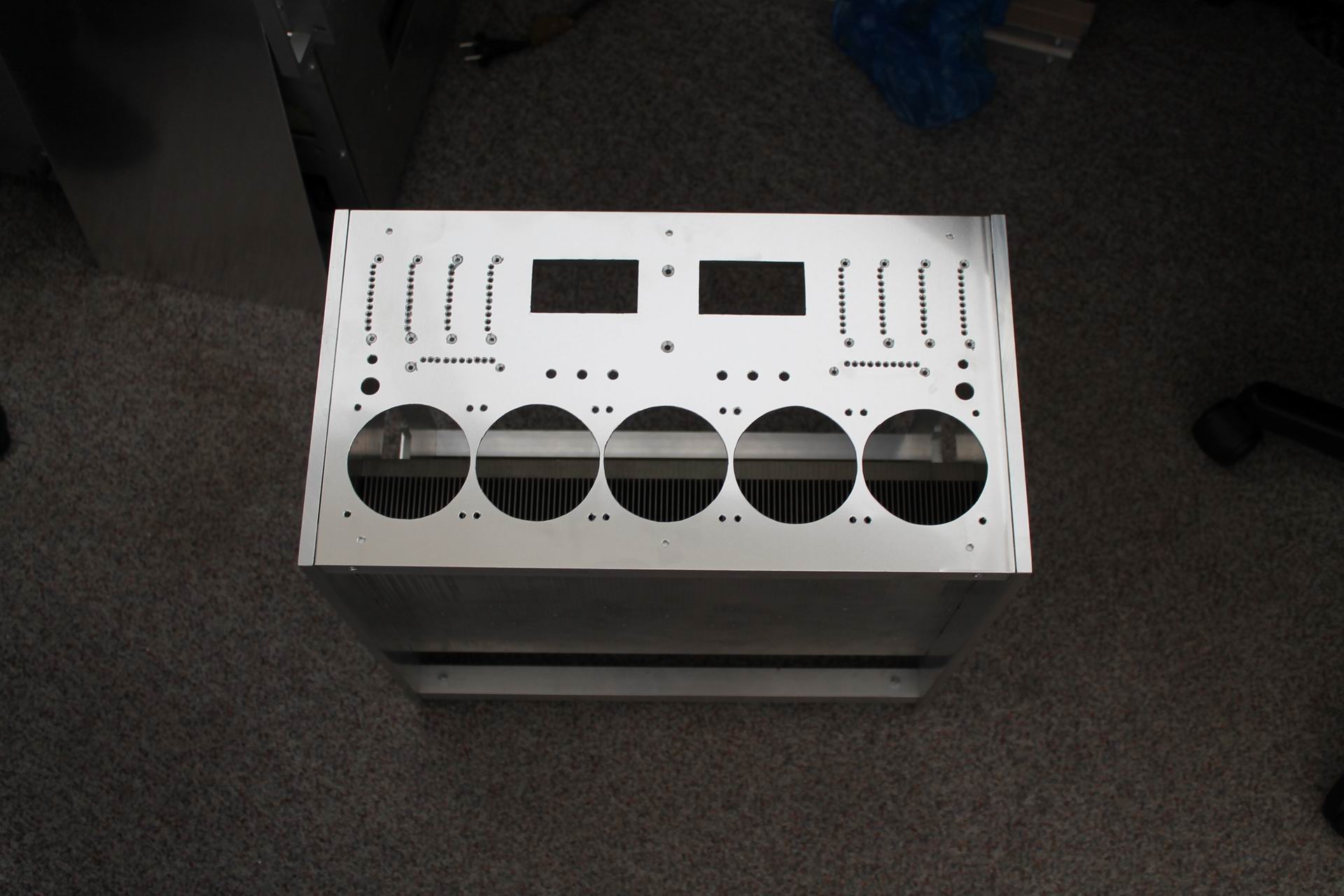
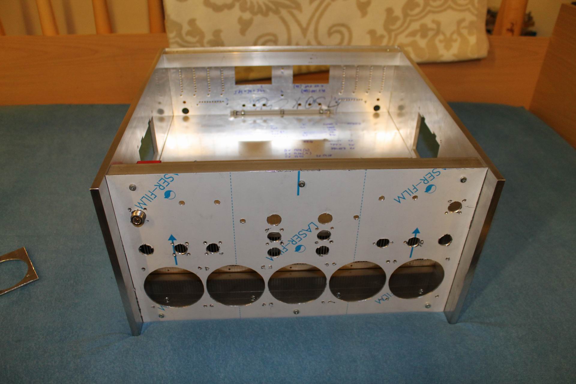
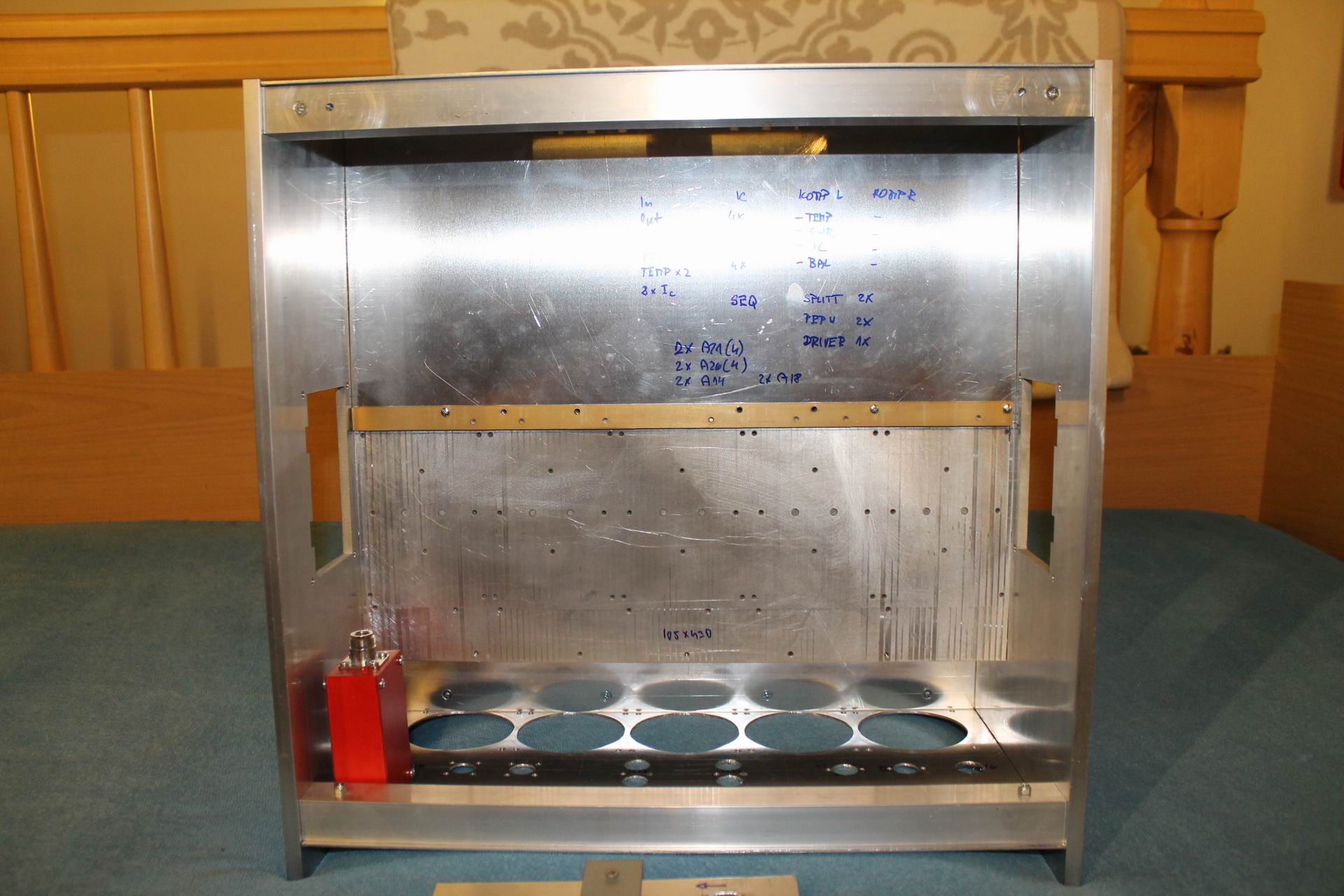
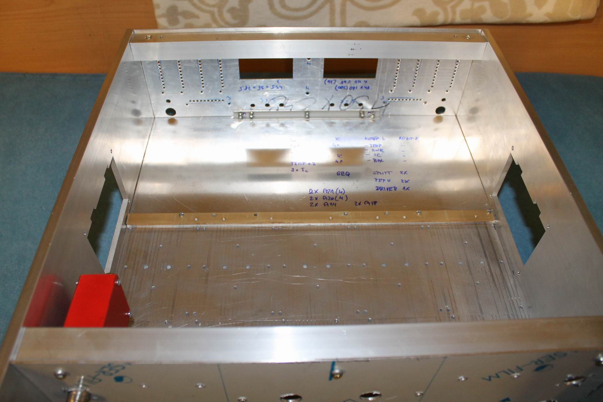
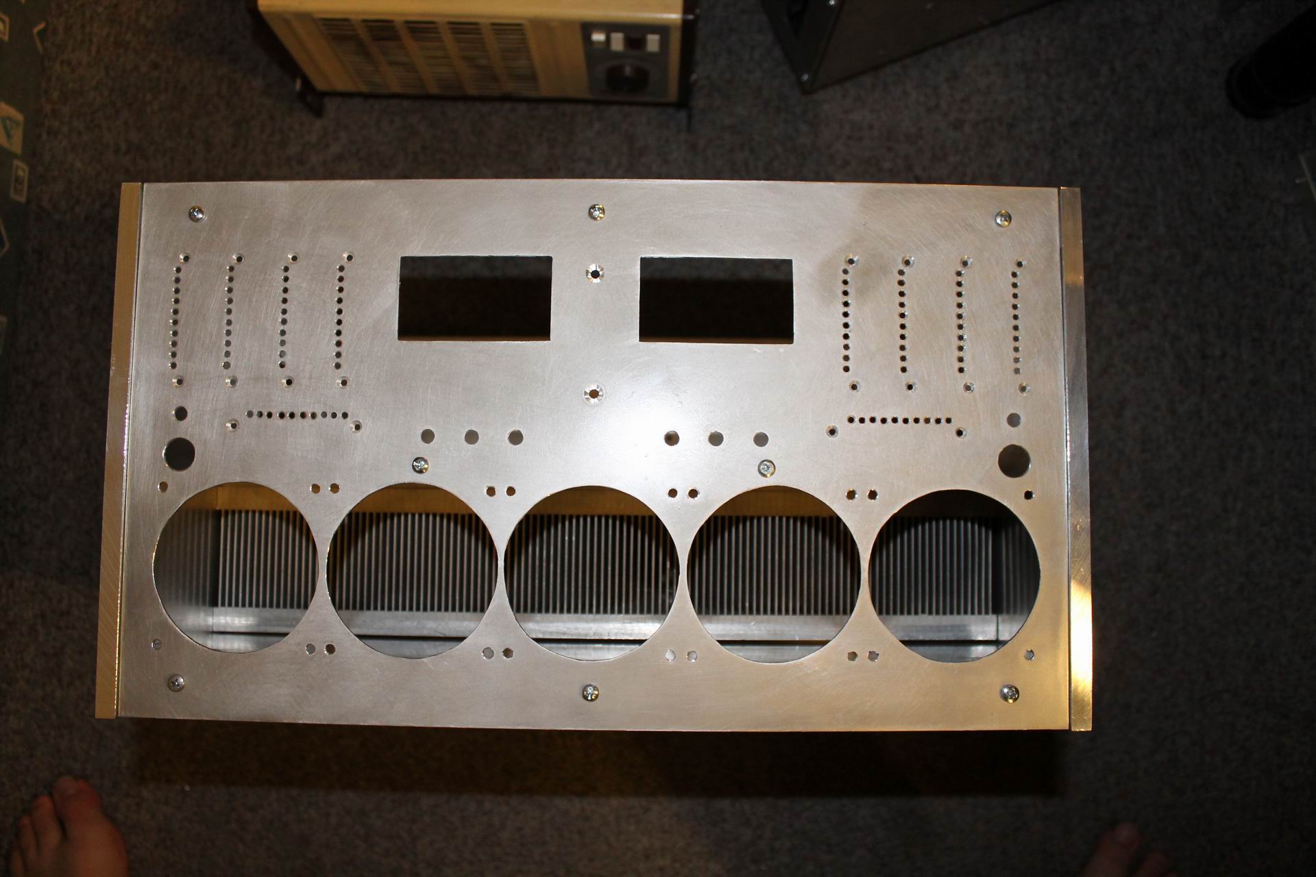
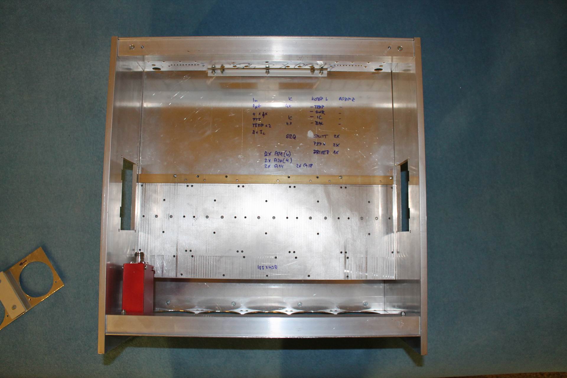
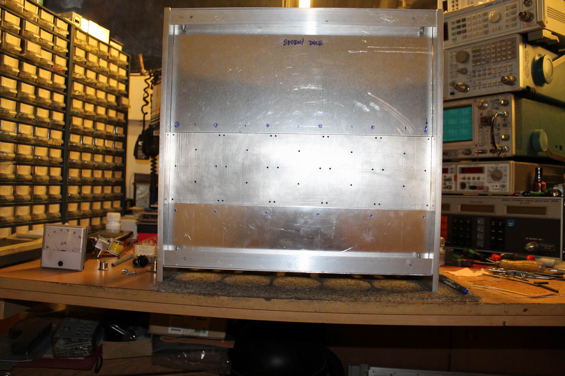
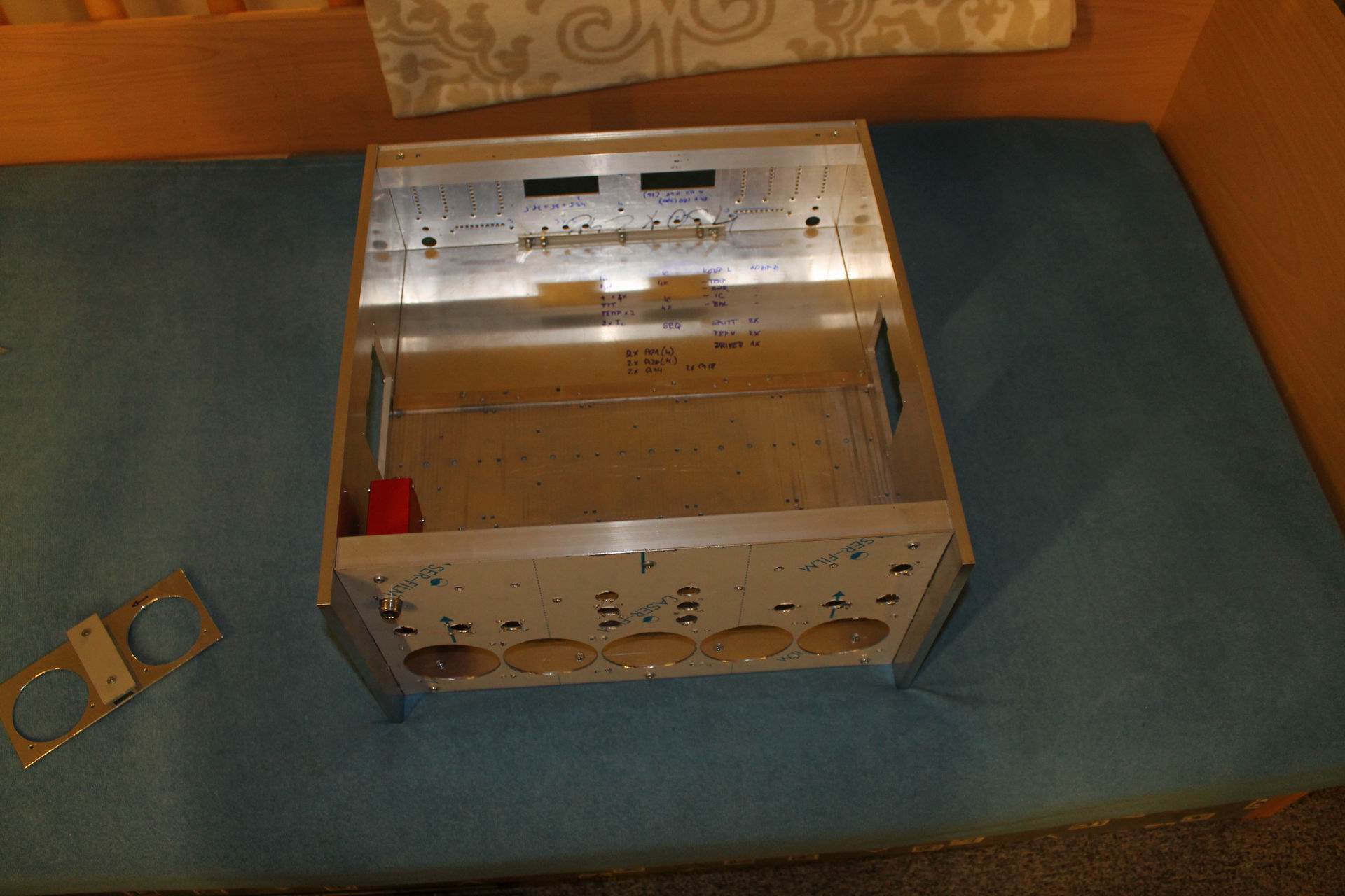
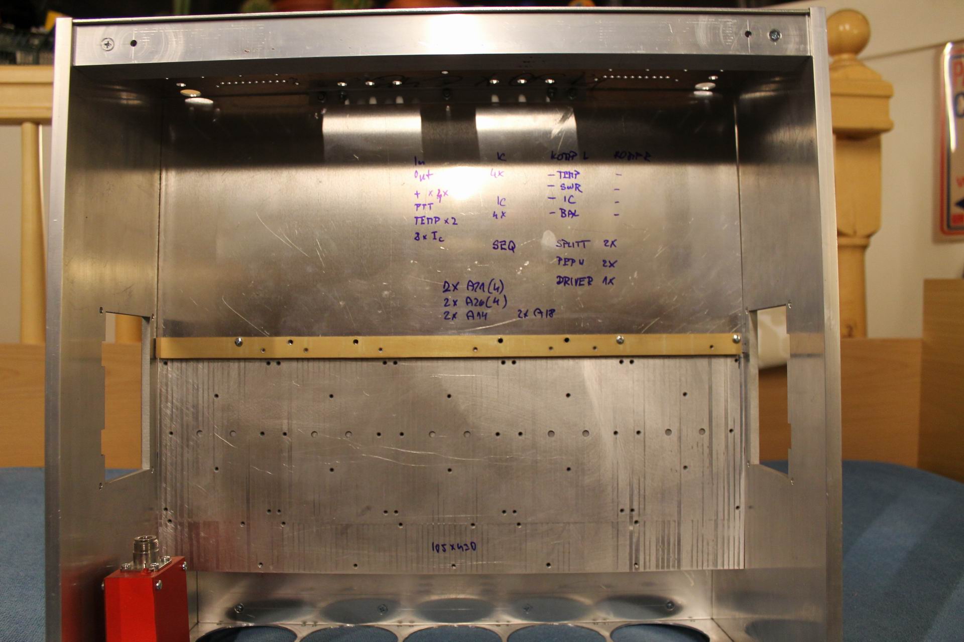
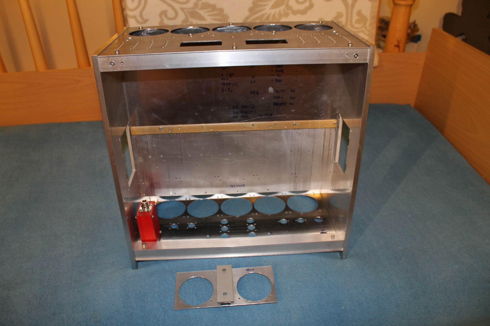
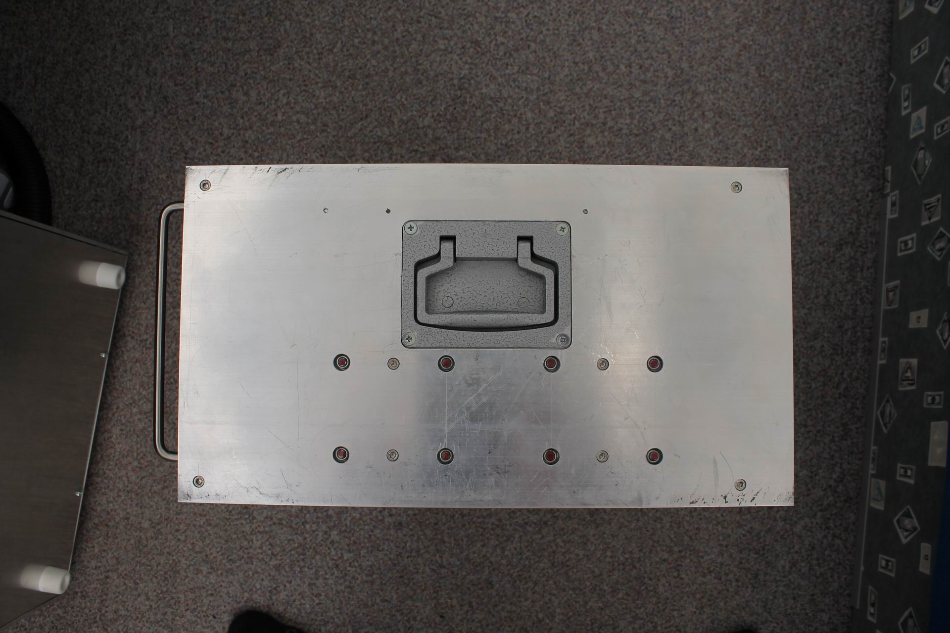
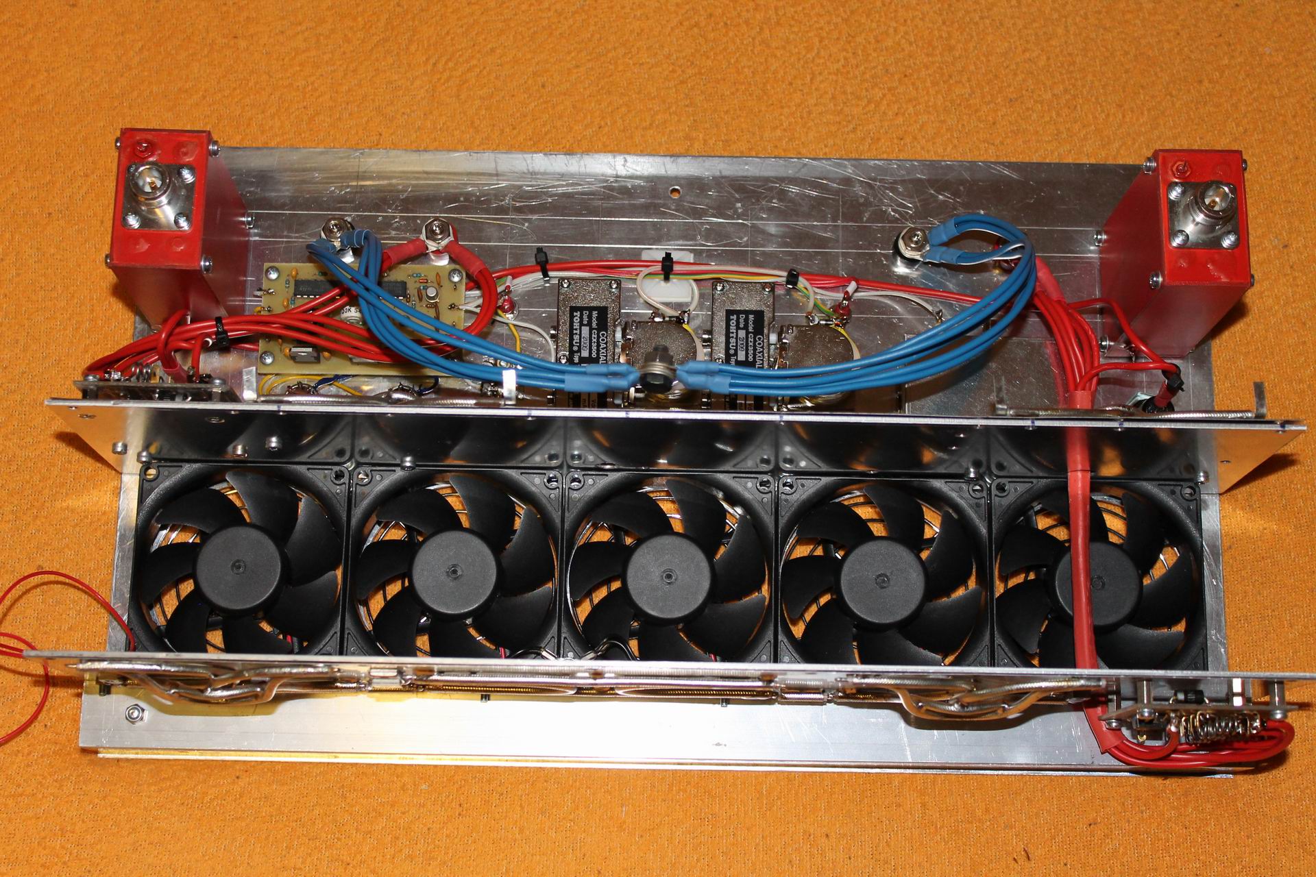
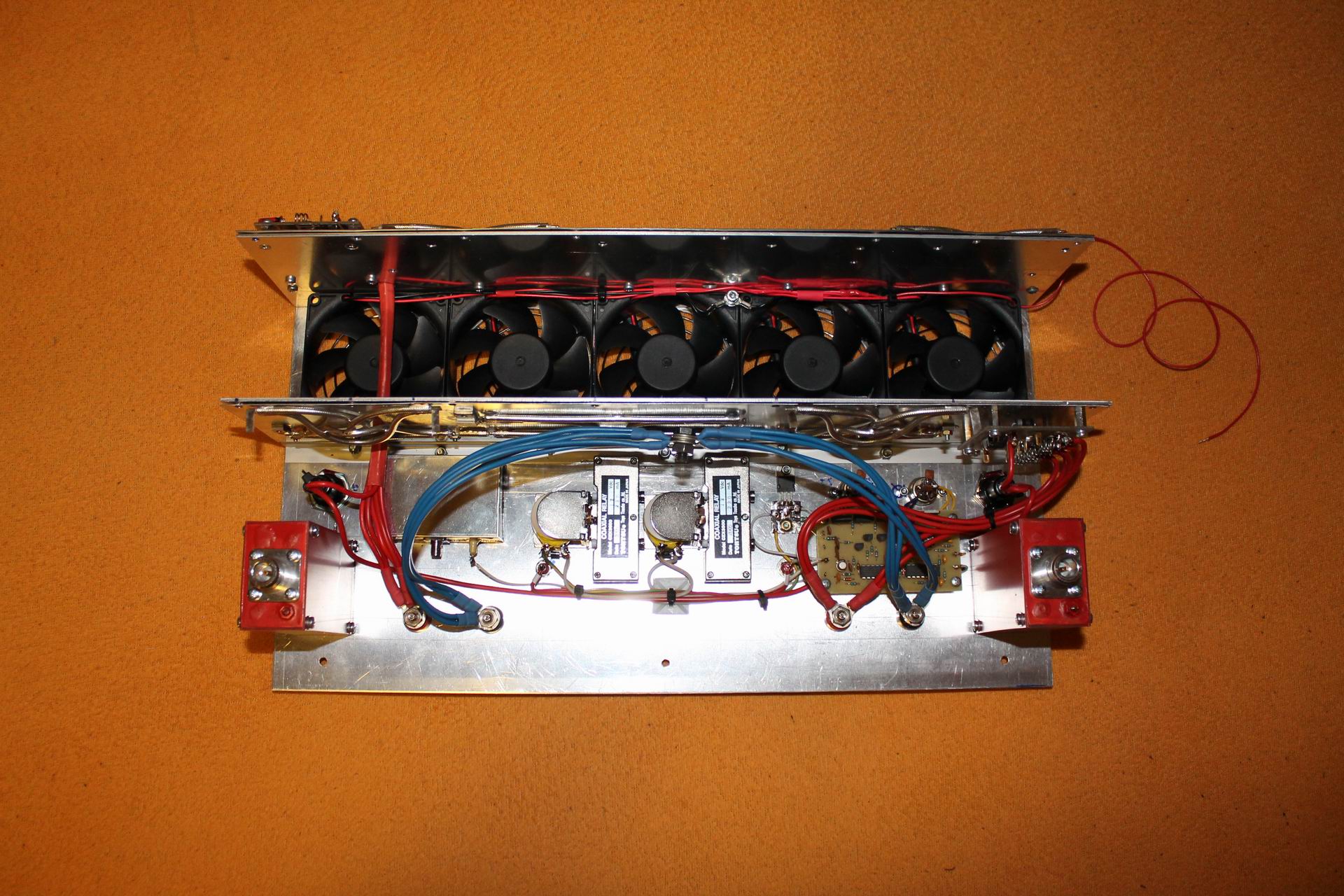
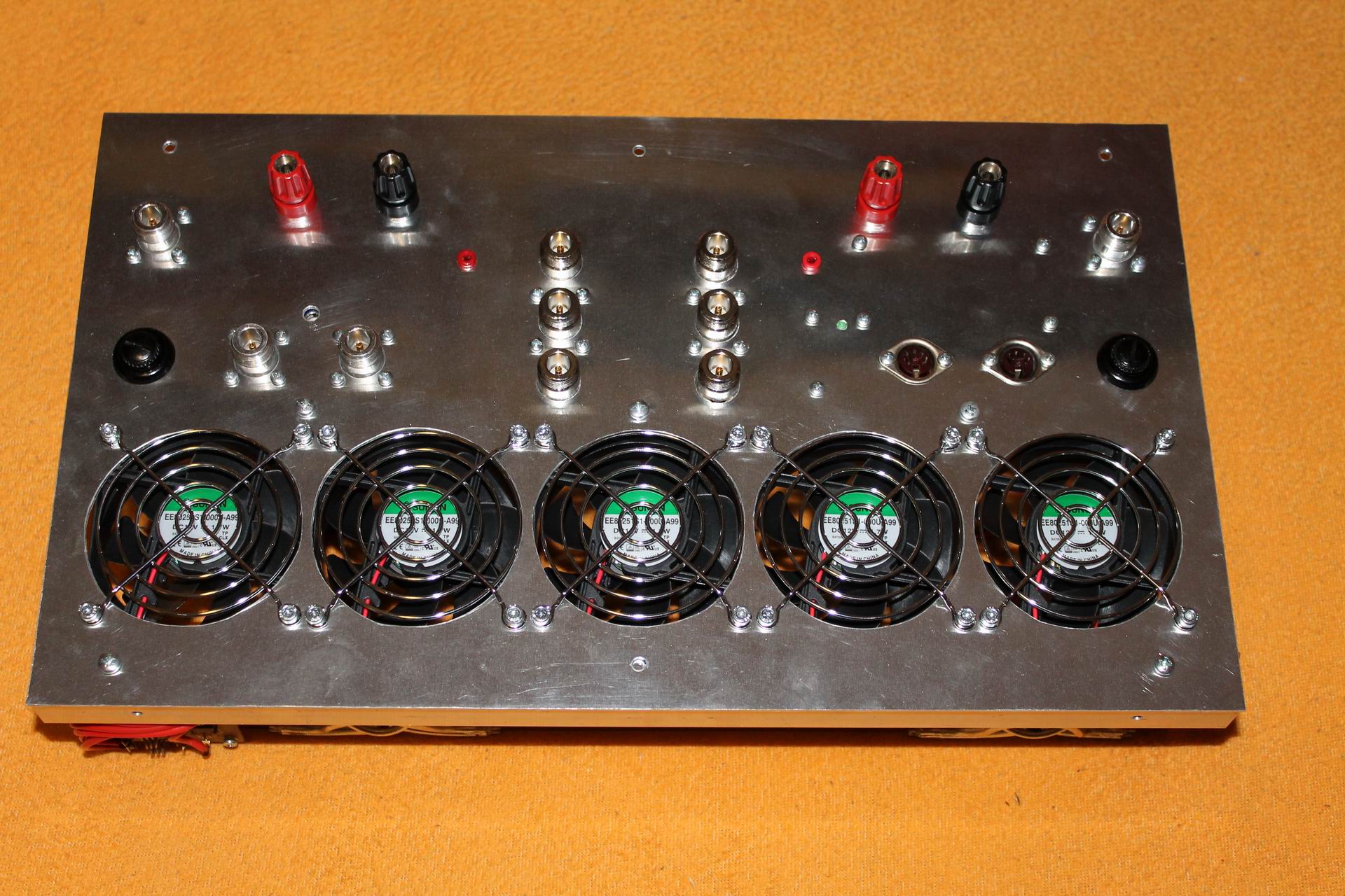
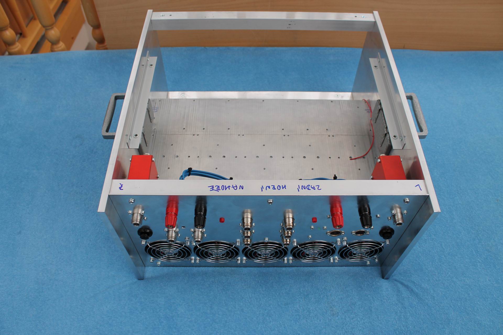
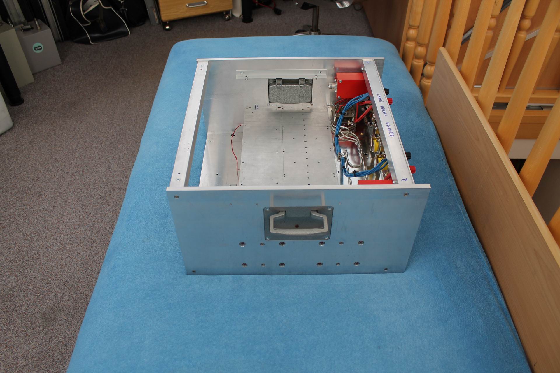
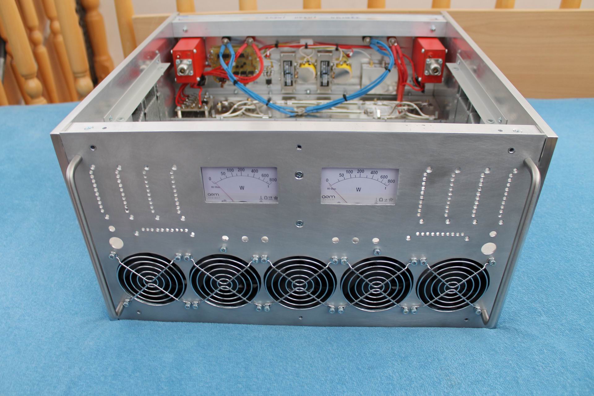
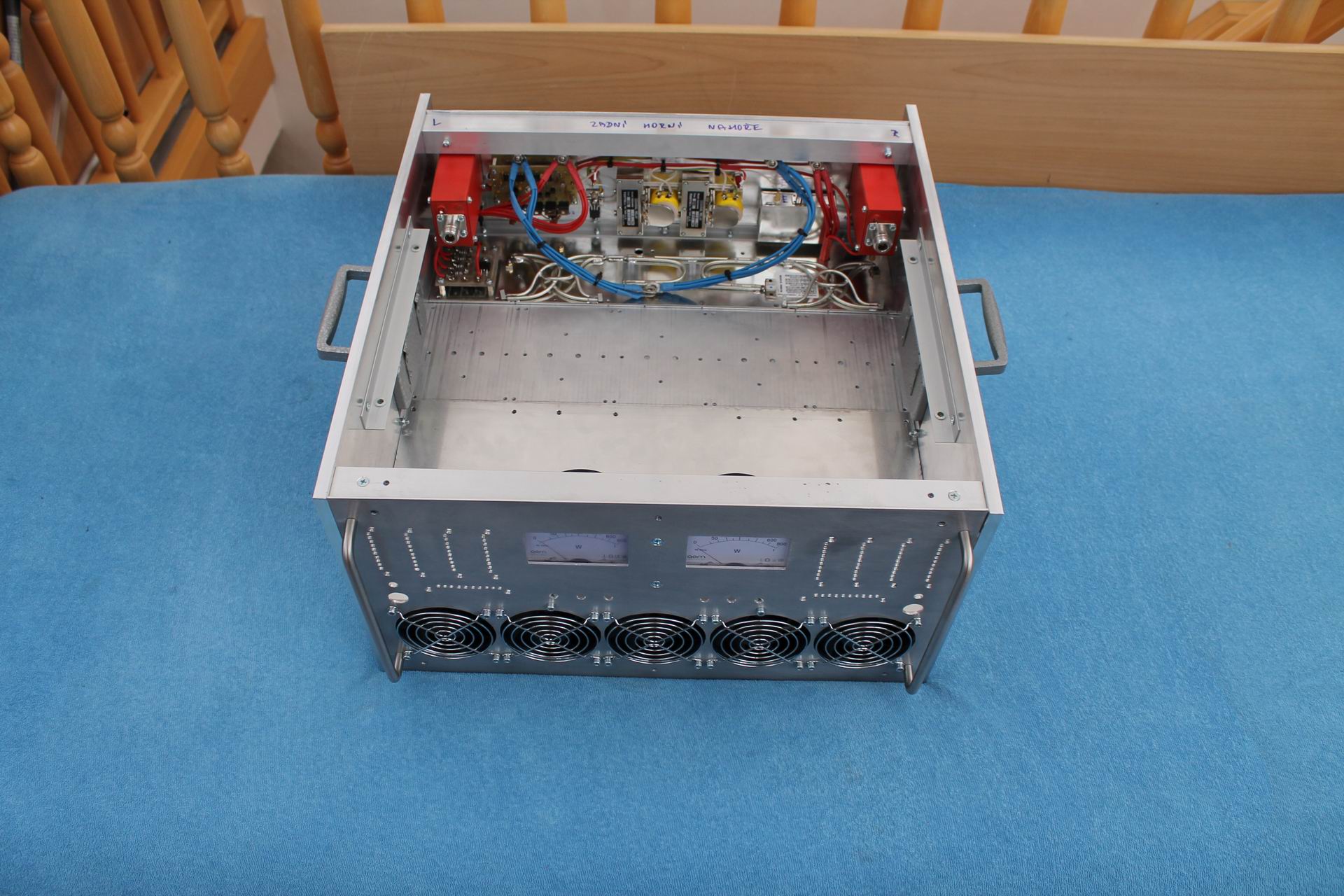
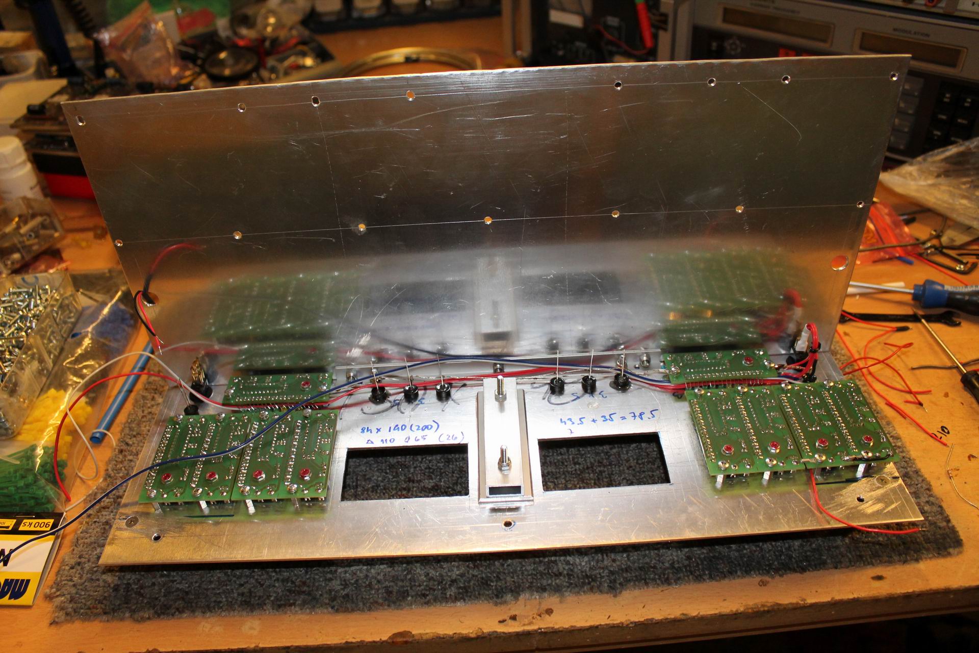
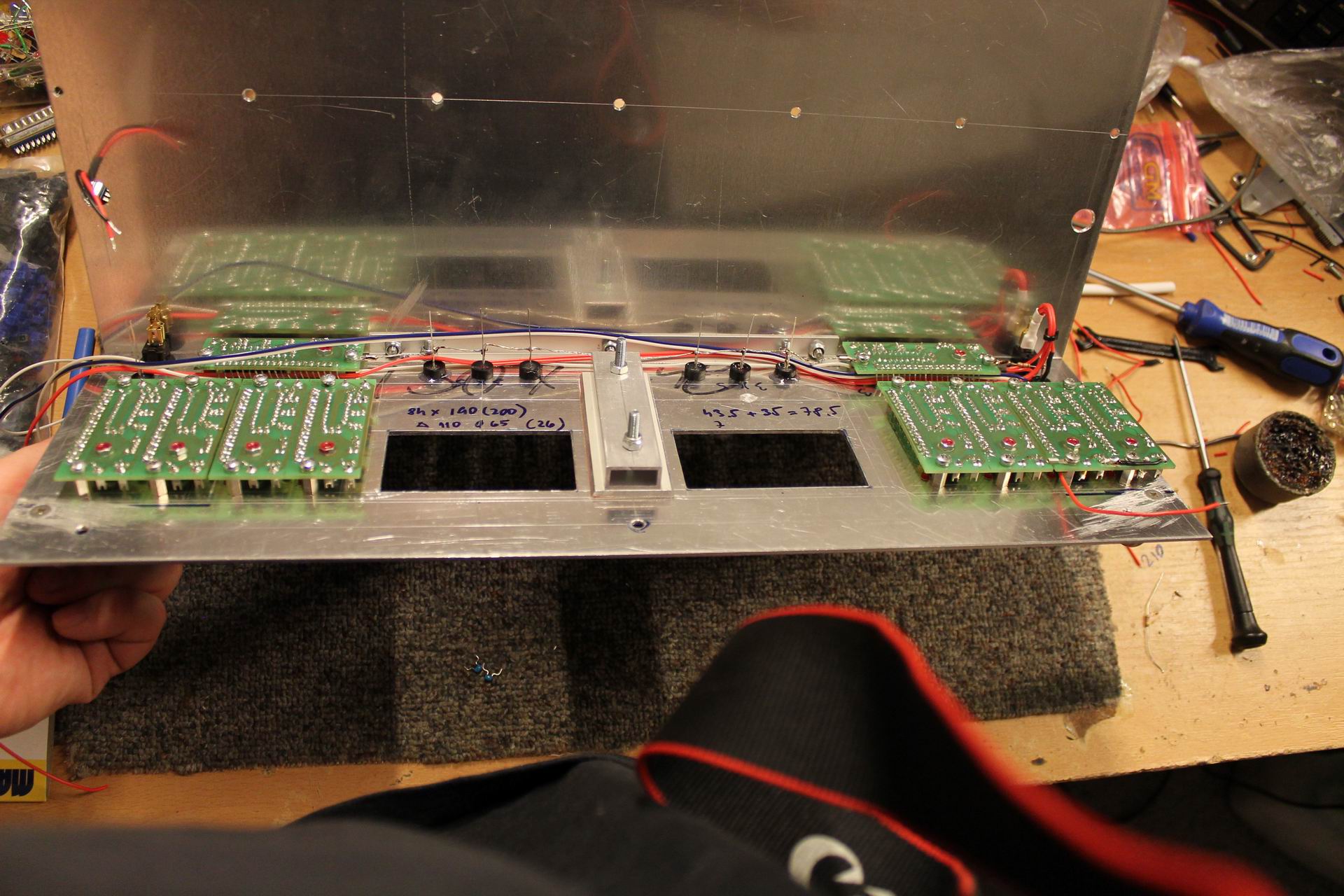
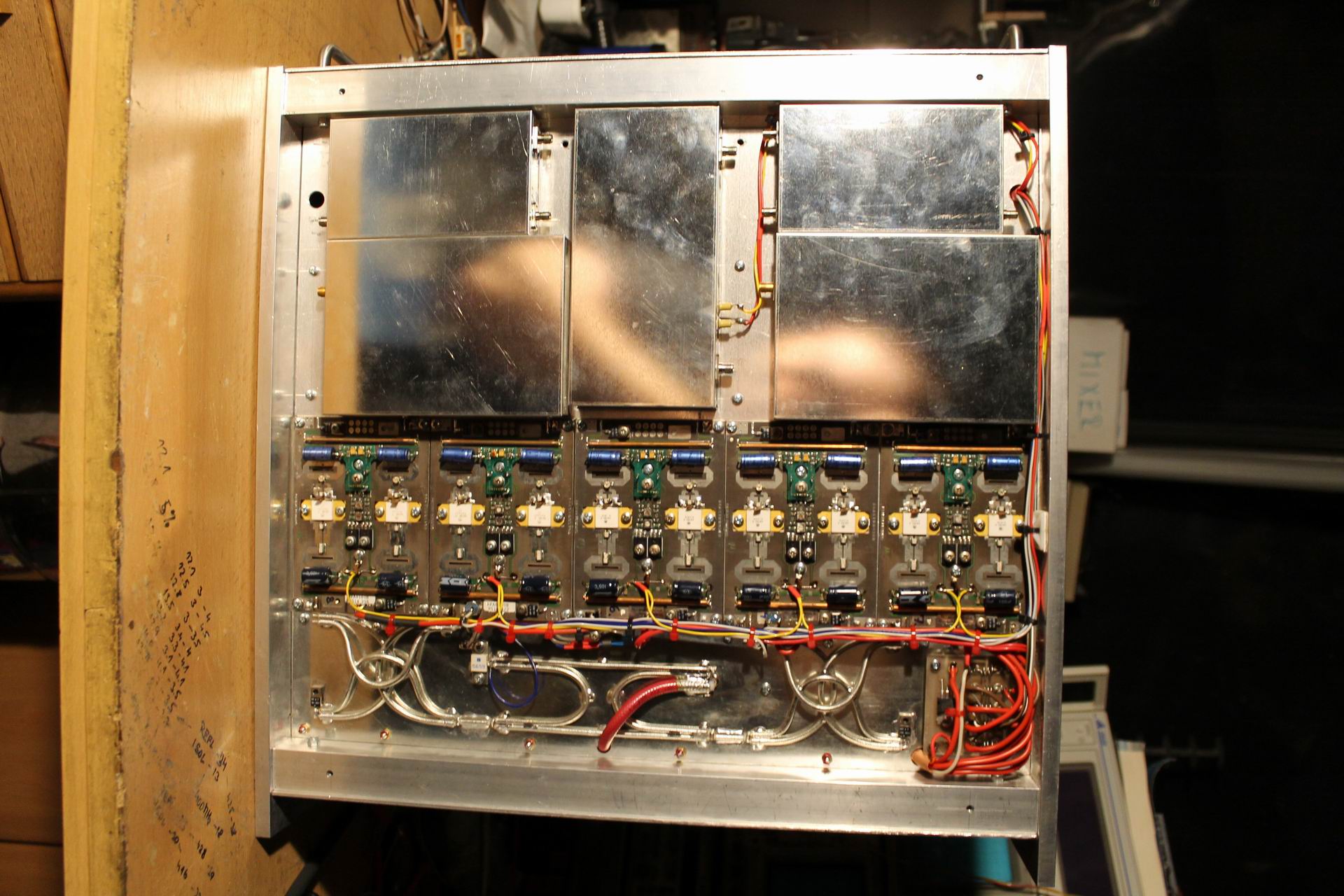
But we wanted to use this PA also for UHF contesting and that means that PA should be easily transportable to contest QTH. It means that the mechanical structure of the PA must be portable, robust enough and above all stowable in a car trunk, which the original module definitely did not fulfill. So I decided to completely rebuild the entire mechanical structure, although it meant a lot more of work. The original kW TV PA consisted of seven 180W solid state units (6 were combined into one output and the 7th was a driver for those 6). When I measured the heat sink thermal performance I found out that it would be able to cool two such 3kW power amplifiers. Further more if there's enough air flow and the CW TX time does not exceed 3 minutes, I can afford using the radiator from the original PA Telefunken as a two-sided heat-sink, that is installing the PA modules on its both sides. But the length of the heat-sink was over 60cm (it is made up of aluminum fins, pulled down by the M6 threaded rods and cut to the plane) so I cut it off and shorten it to fit with the sideboards of the future PA in a standard 19 inches rack like our other PAs:
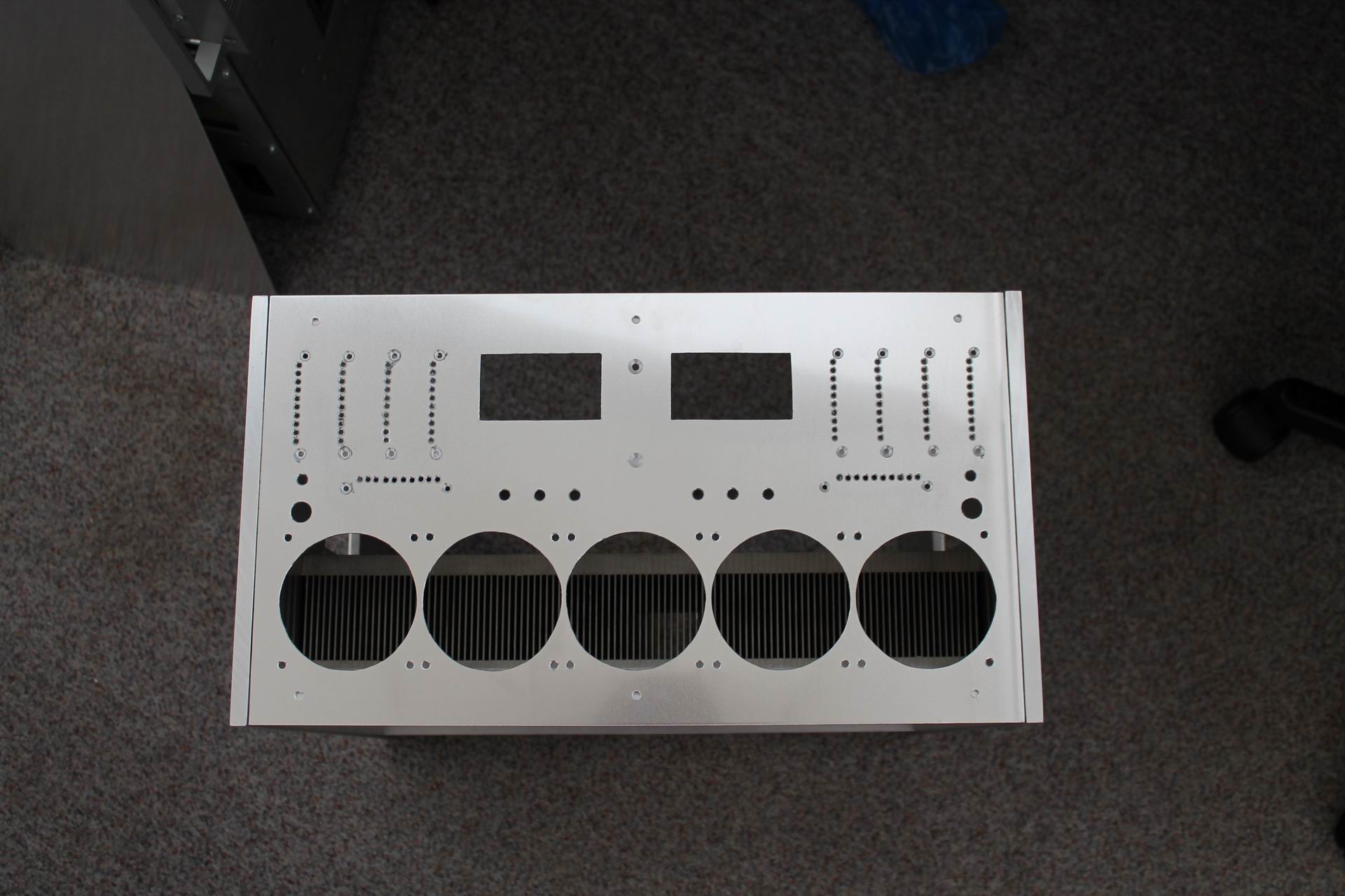
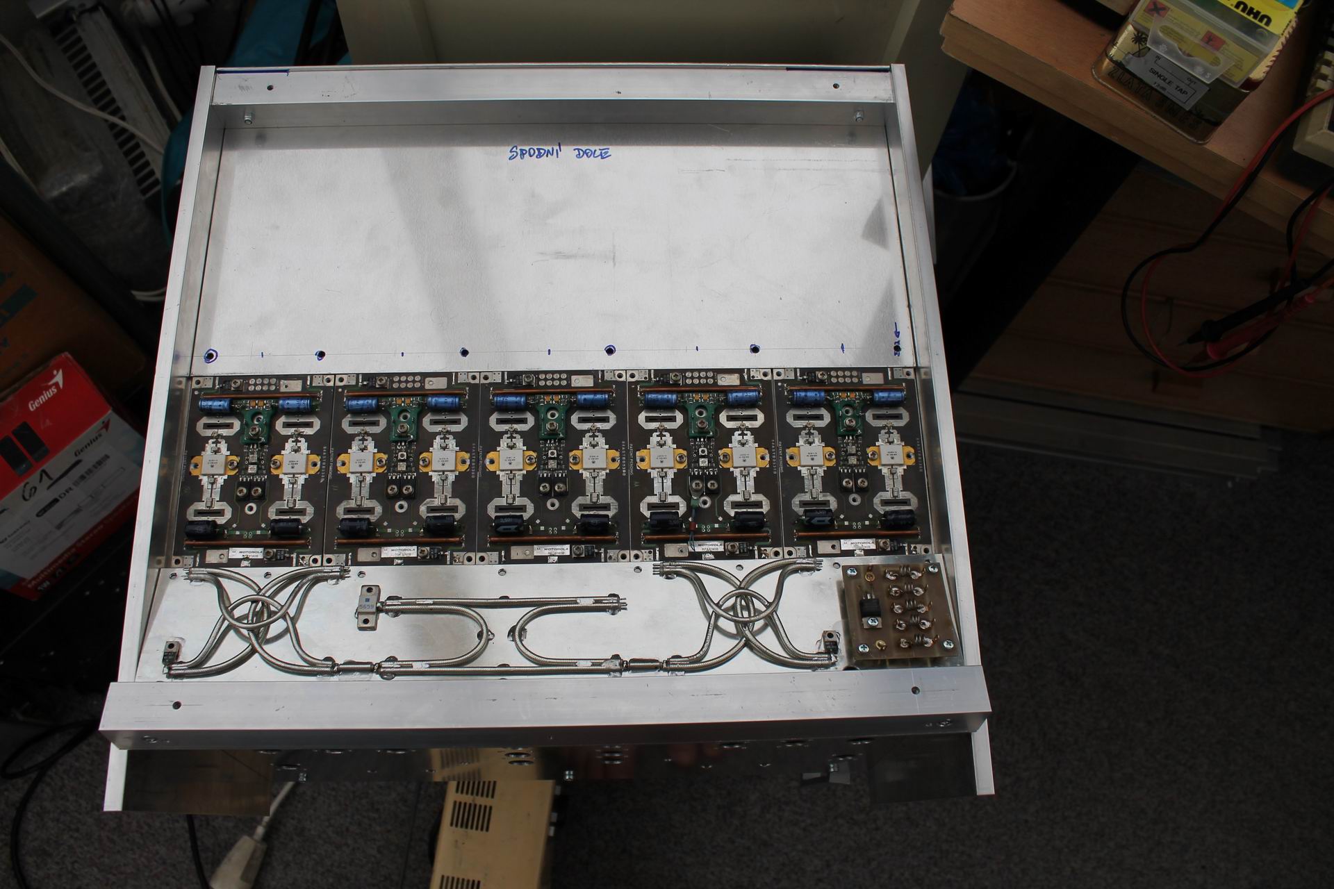
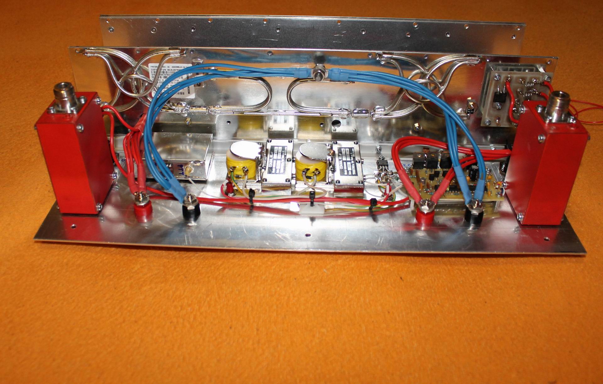
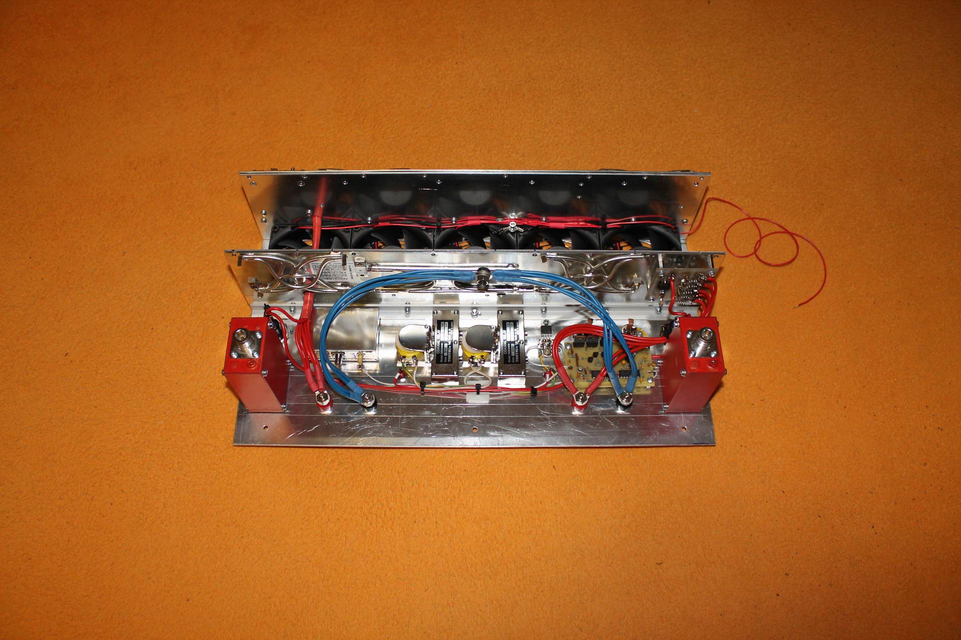
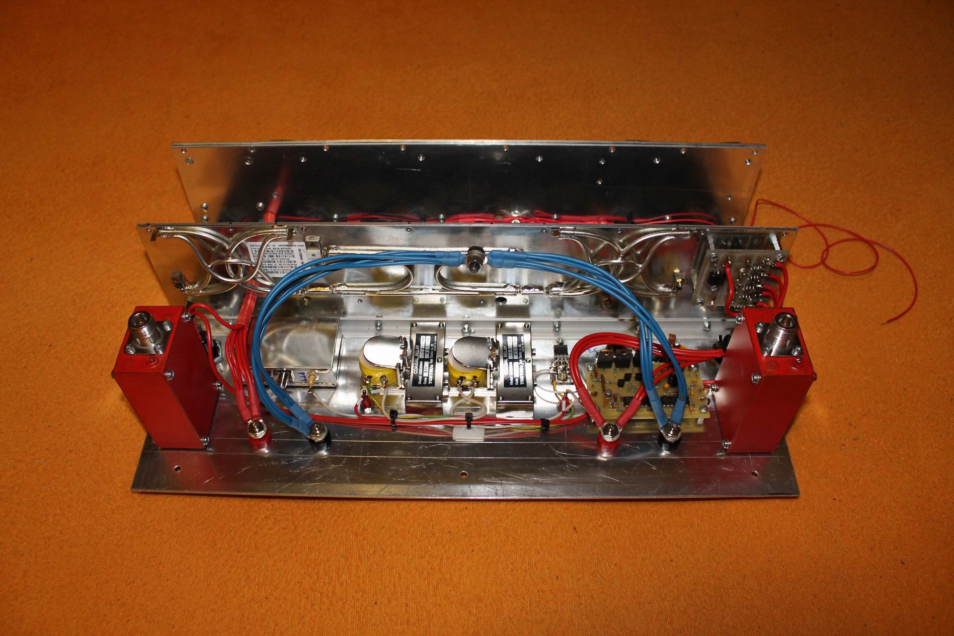
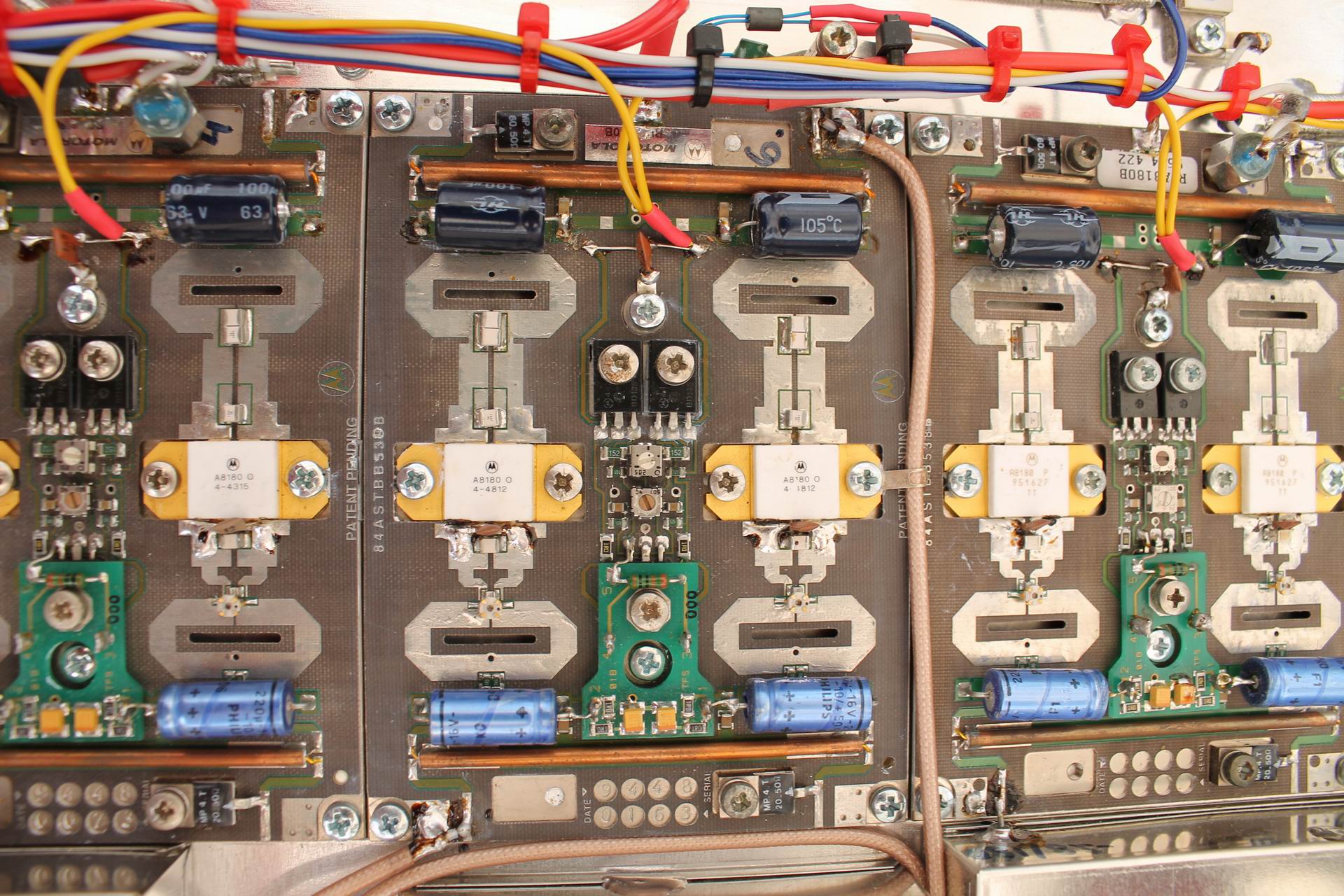
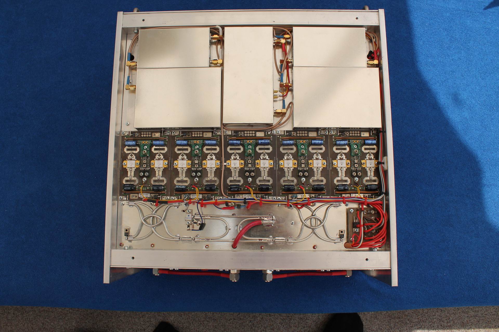
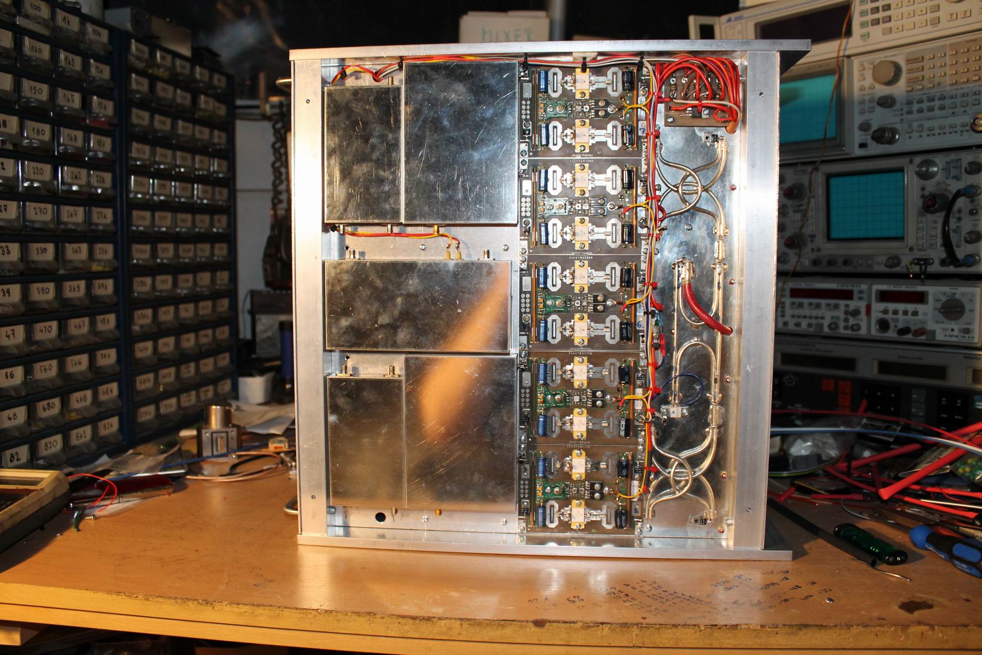
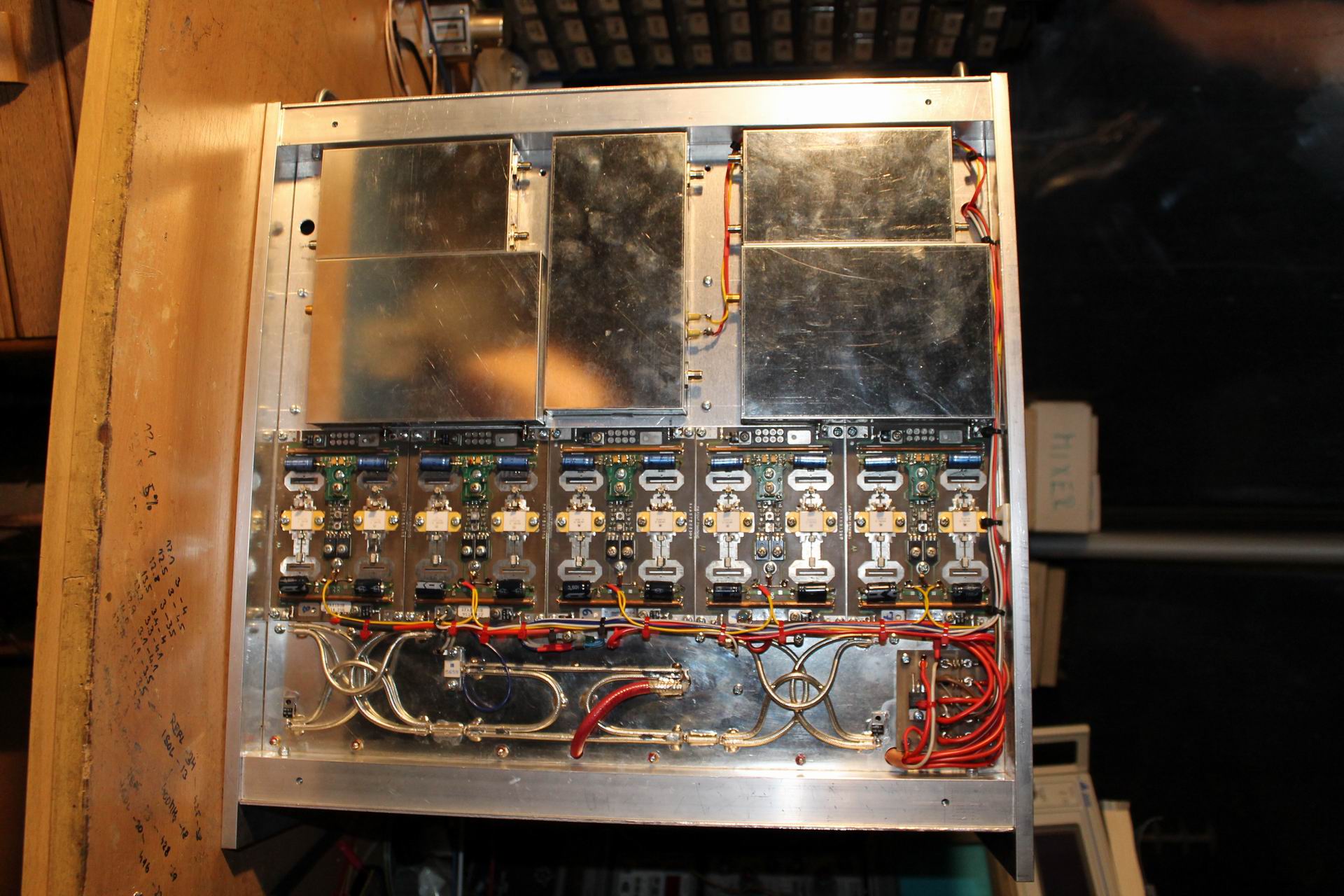
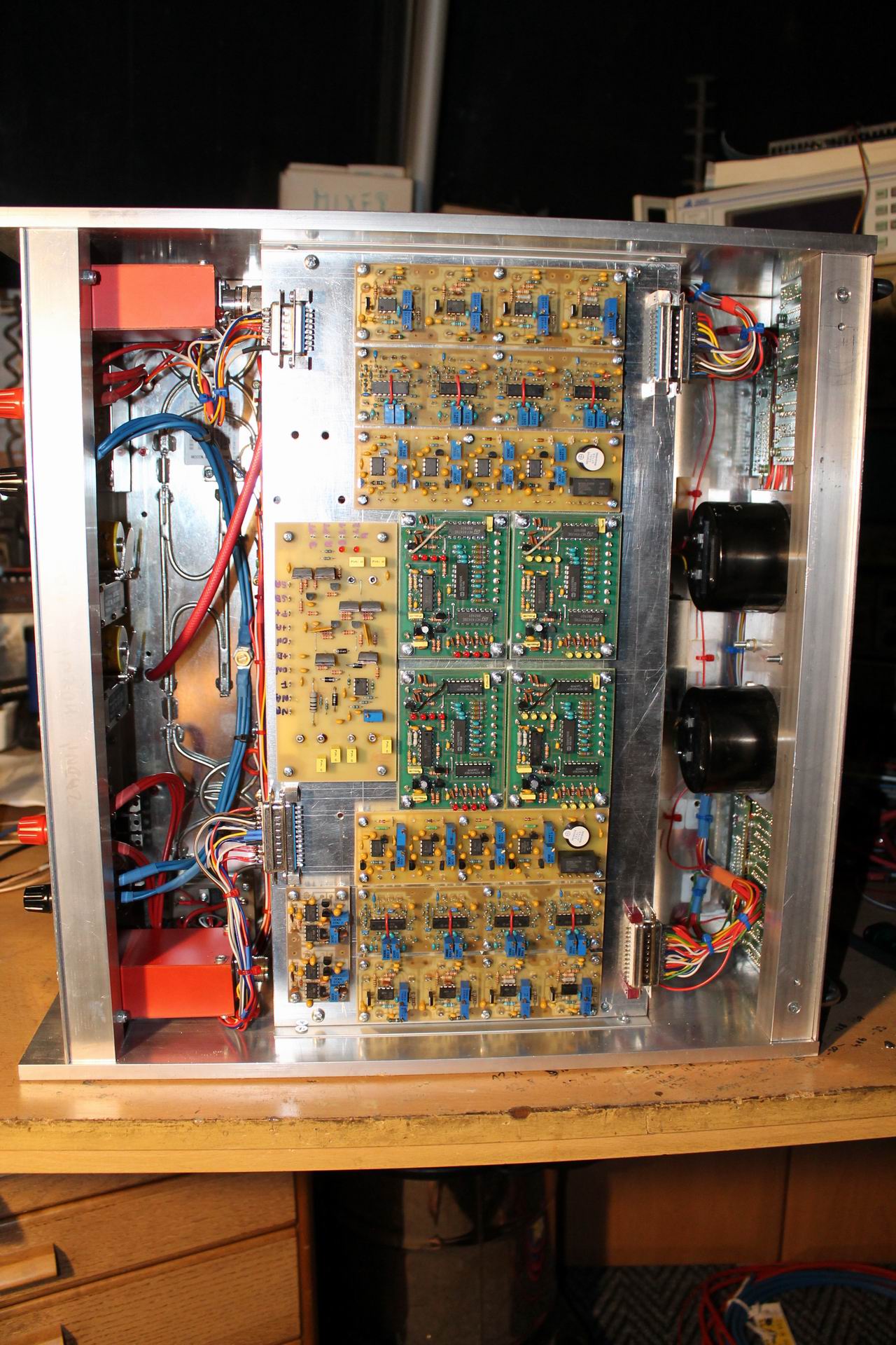
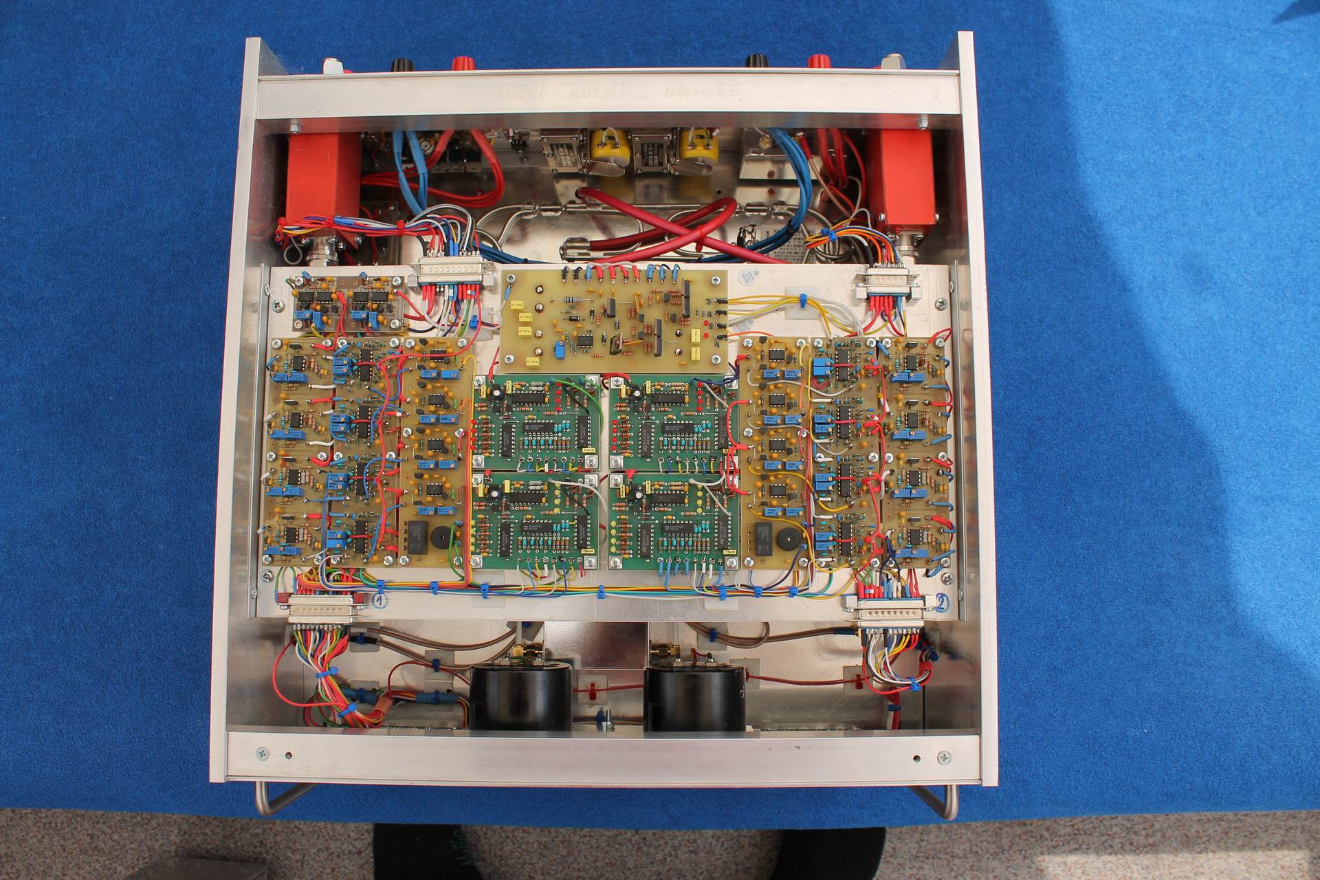
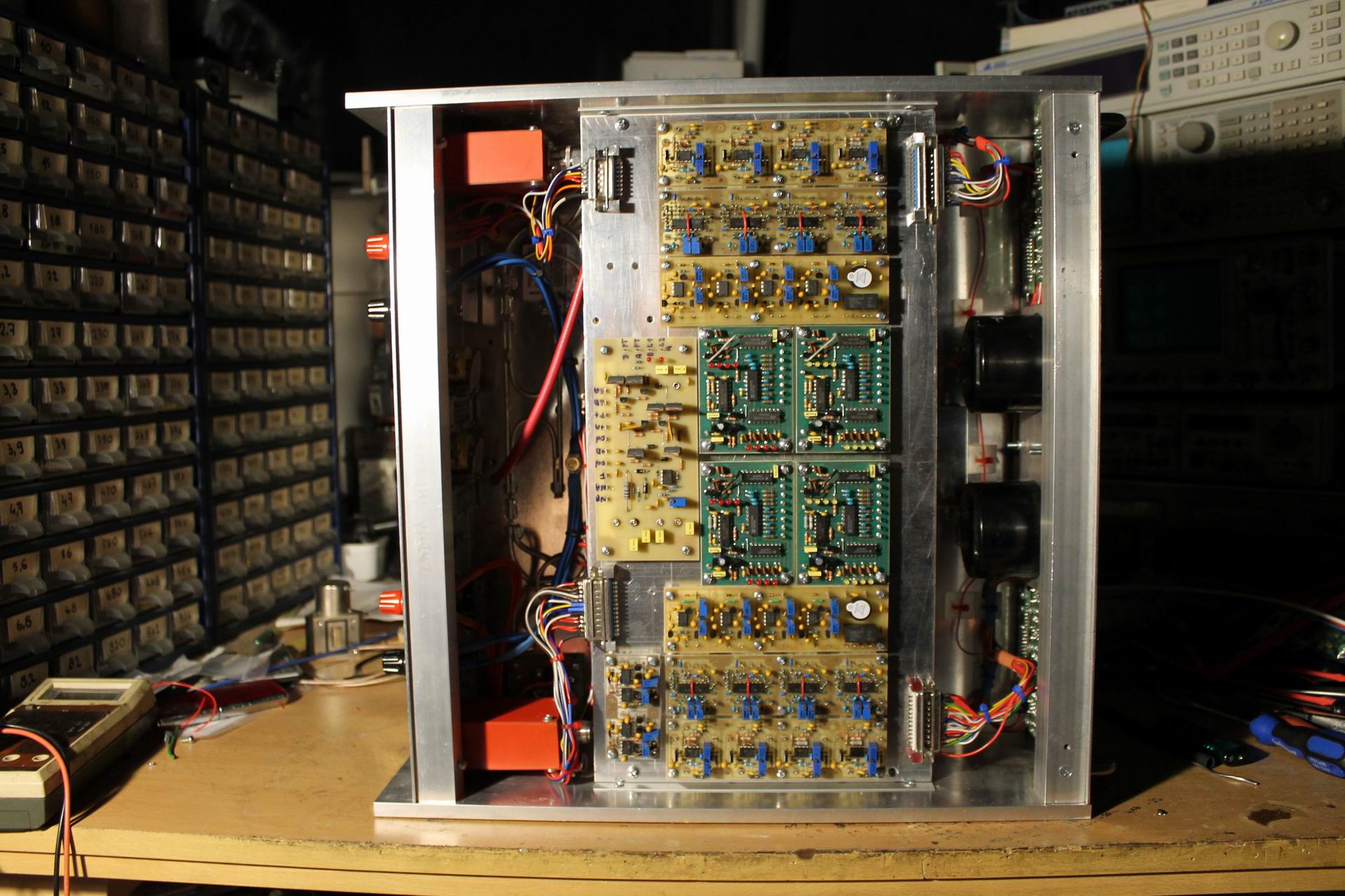
Totally 10 power modules RFA8180b (from UHF TV PA Telefunken) are mounted on both sides within this size. Each of these modules is capable of giving 180W CW so I chose a dual PA configuration (two separate PAs in one box with one common driver), each side of the heat-sink carrying 4 "end" amplifiers merged into one output and one driving module. The power of each half of the dual PA should be max 720W. Therefore it merges electrically 4 modules in each half of PA, which looks like this:
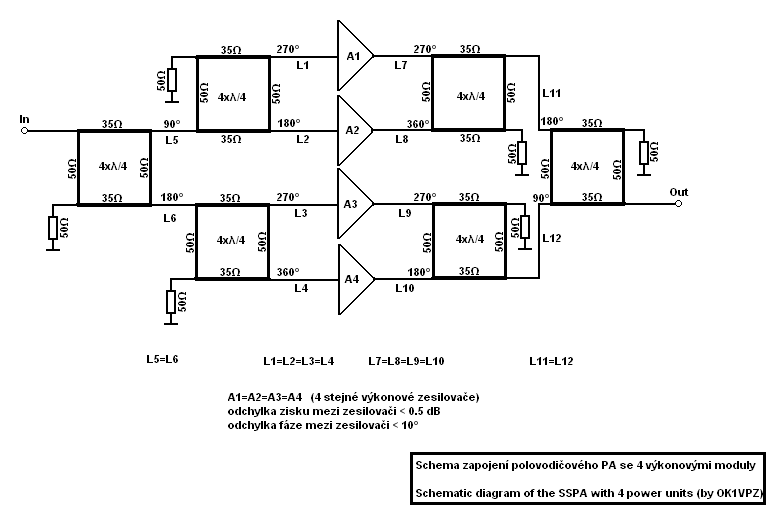
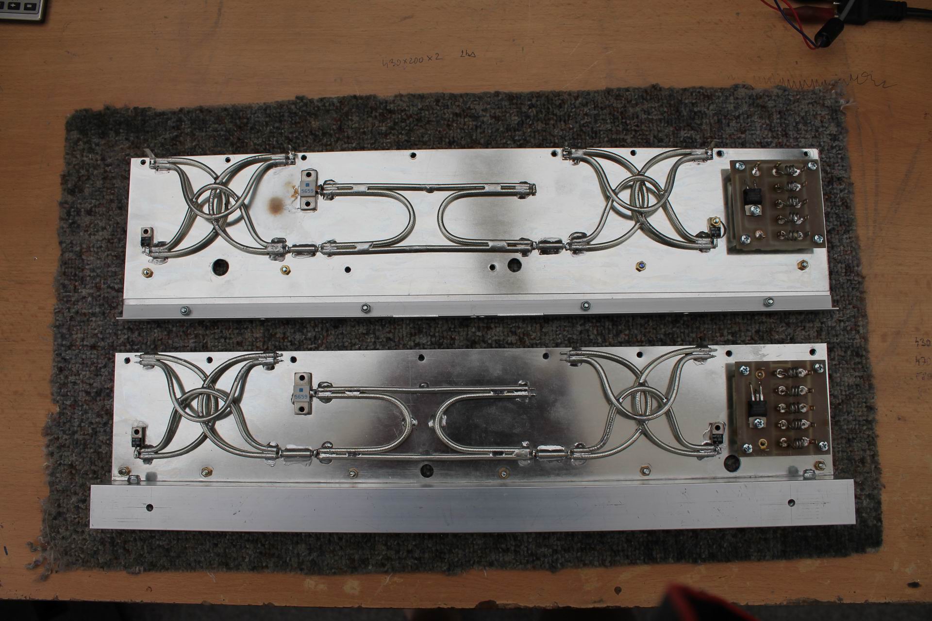
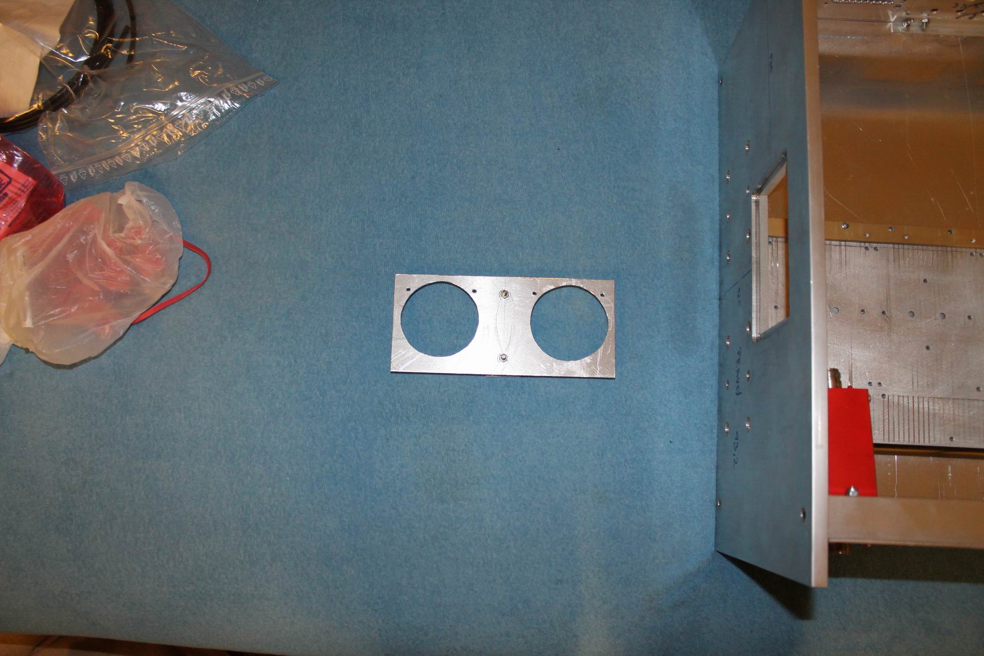
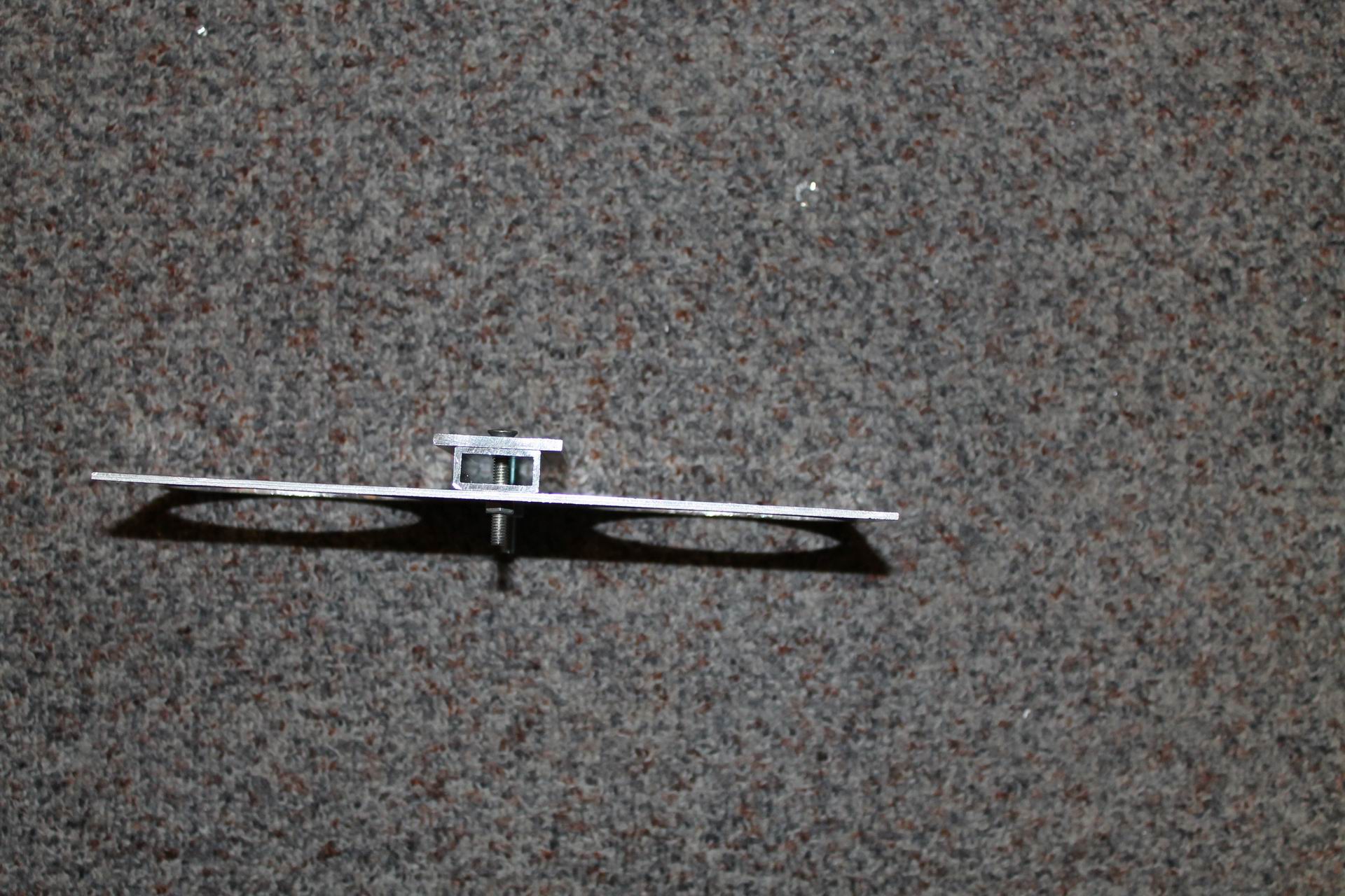
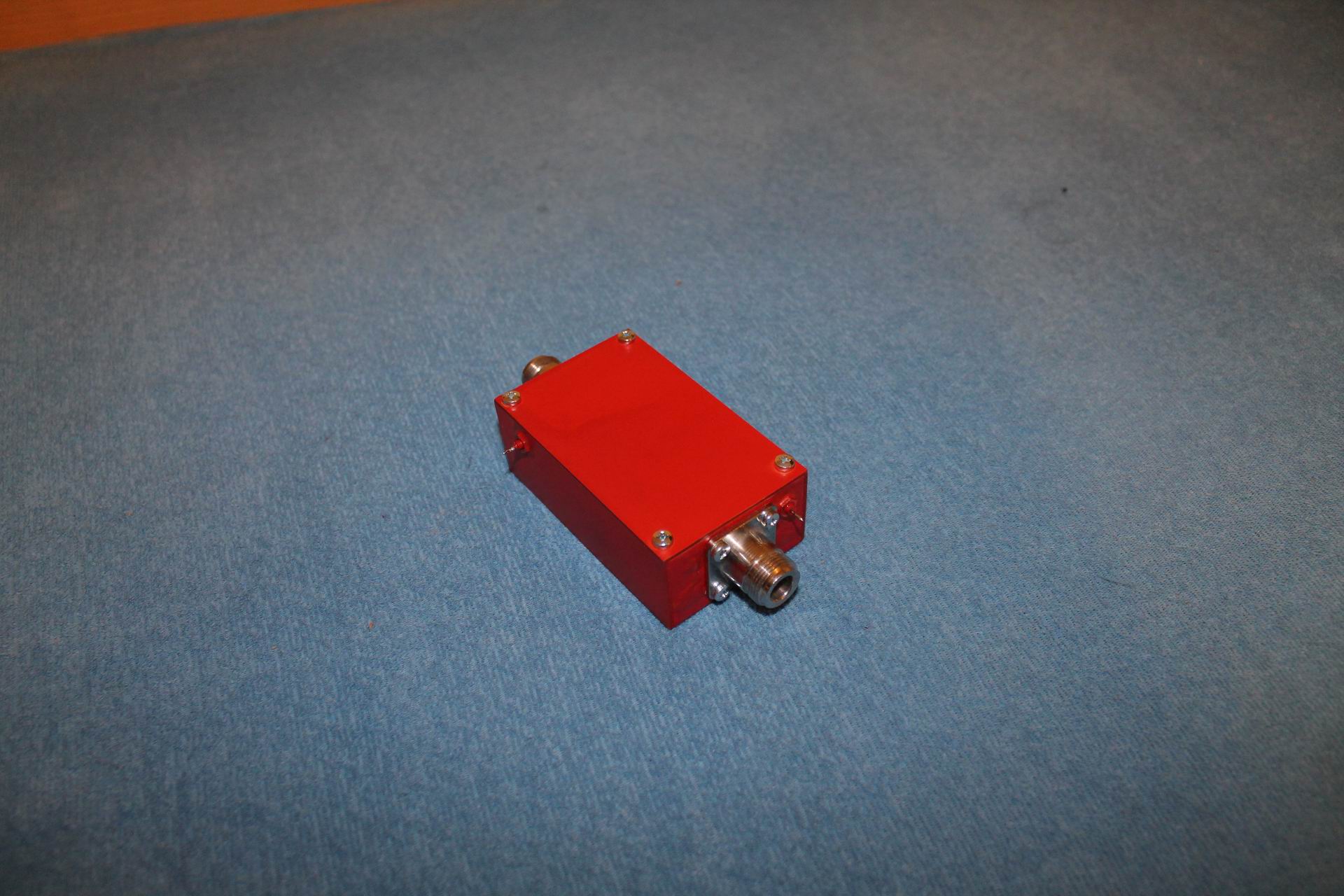
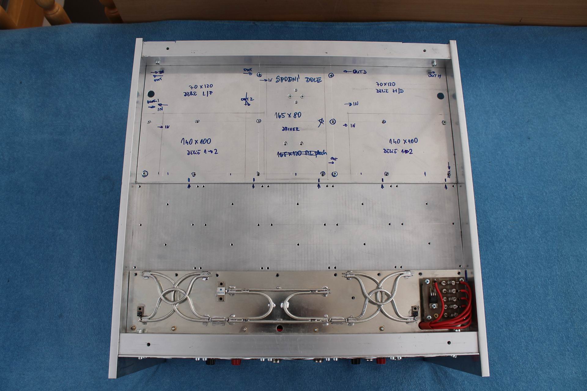
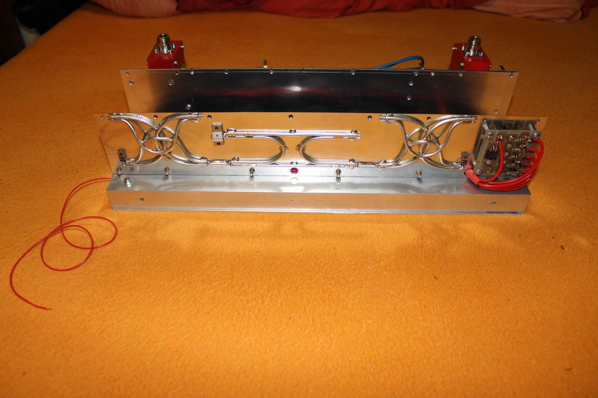
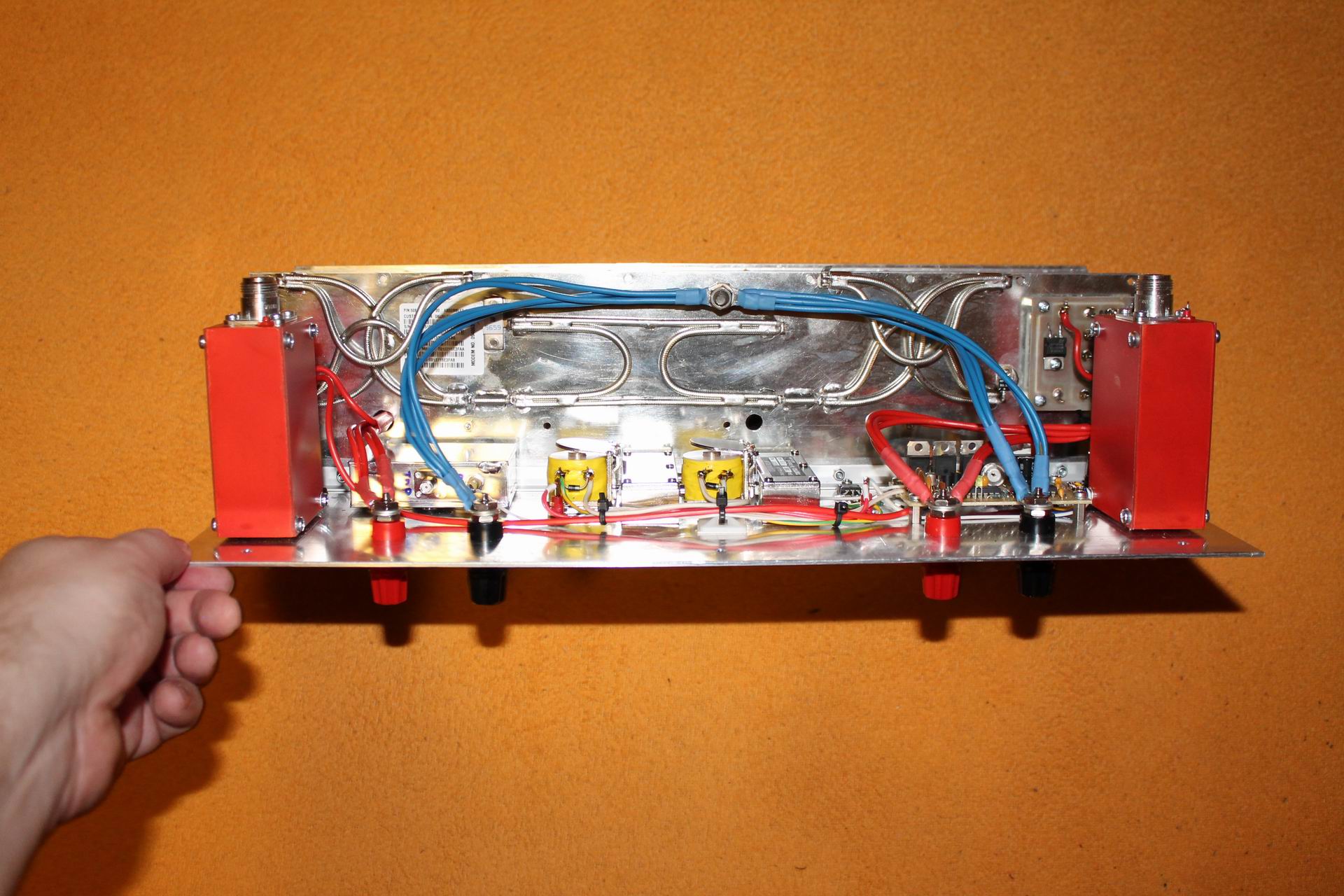
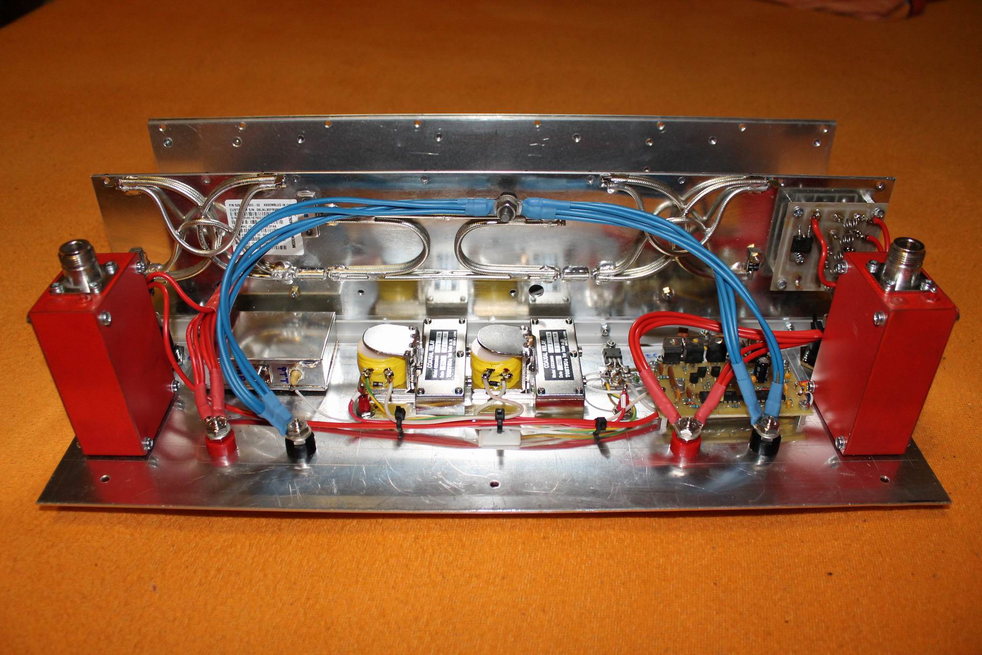
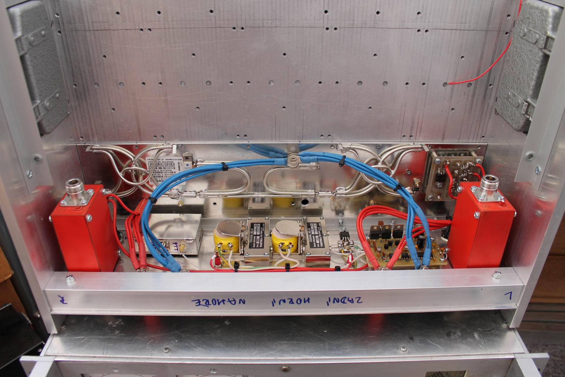
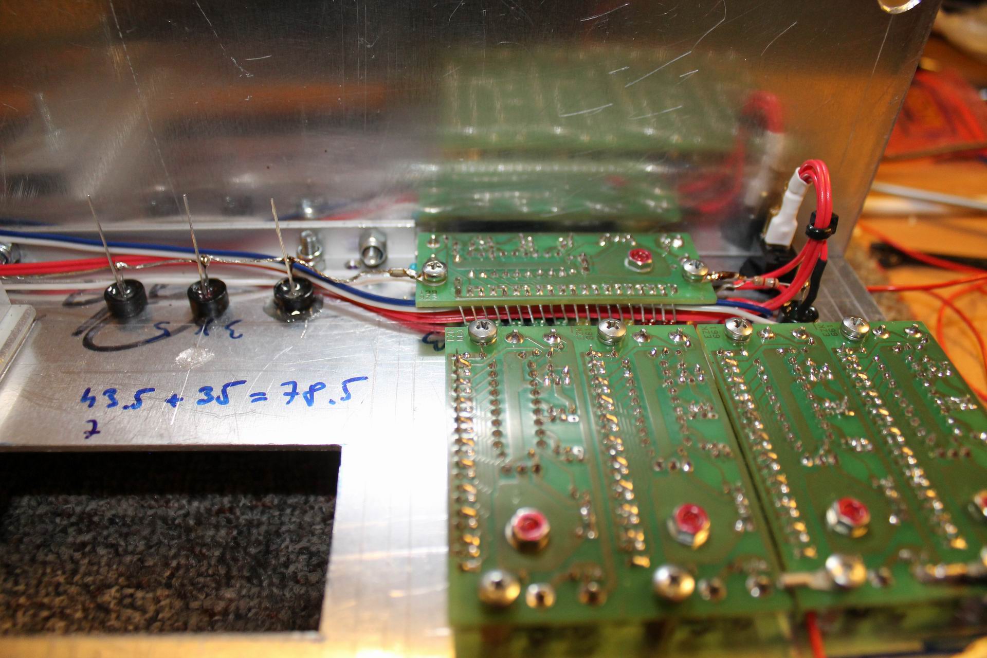
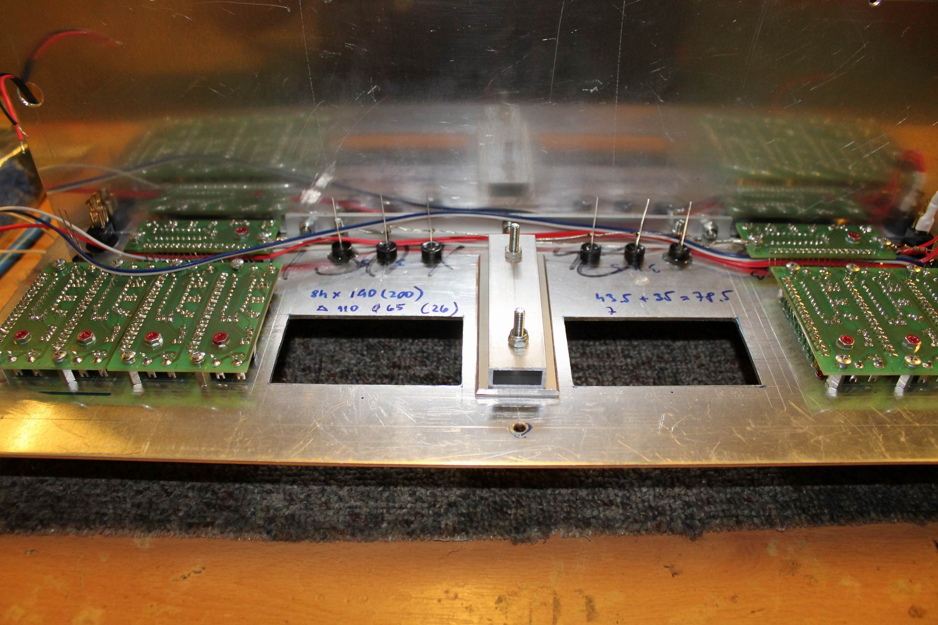
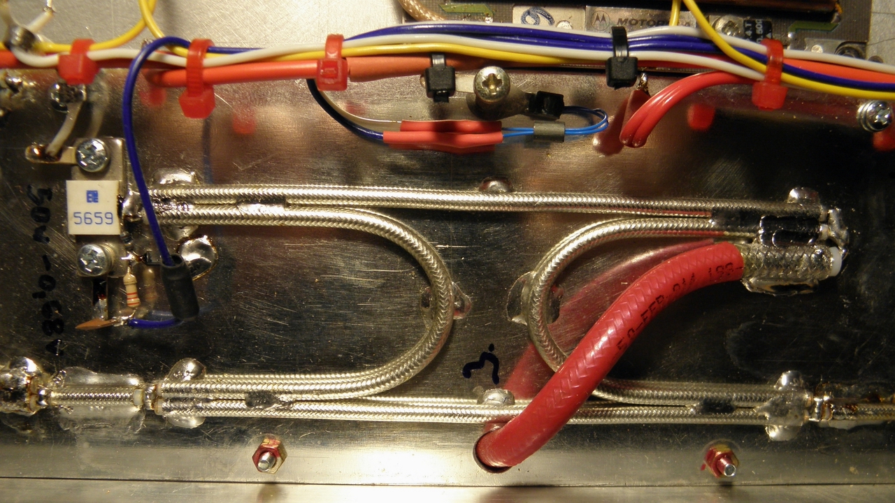
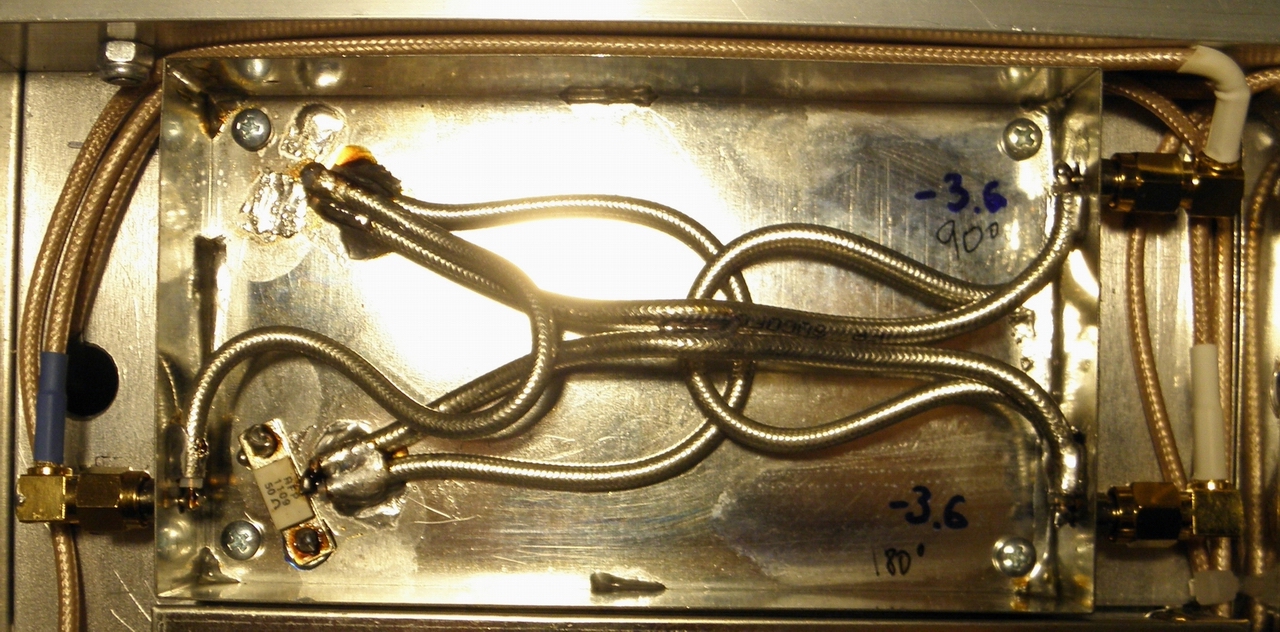
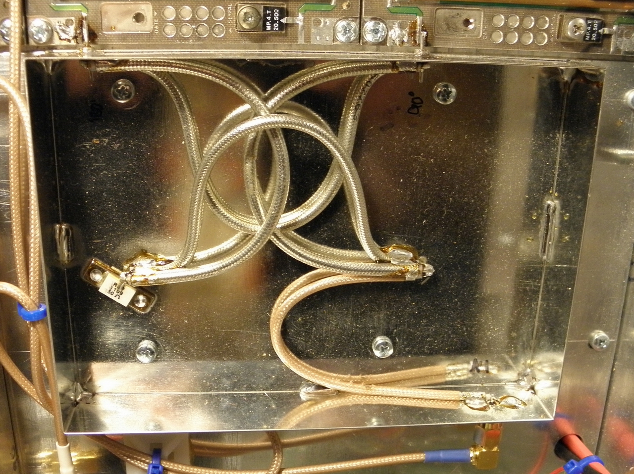
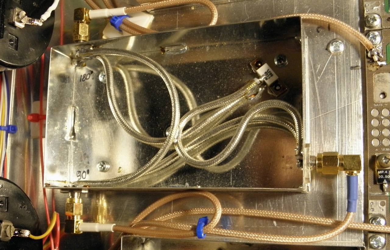
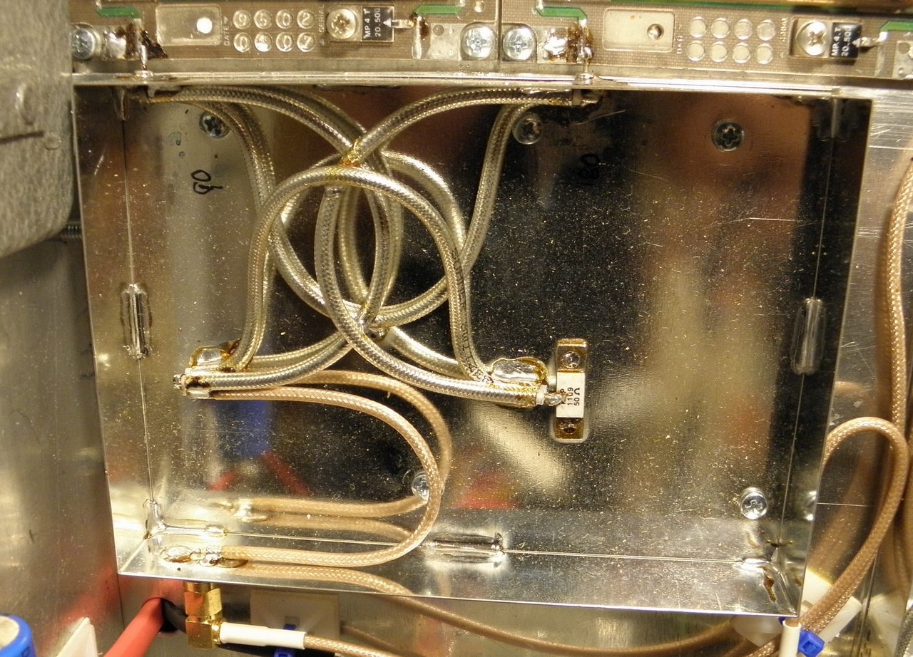
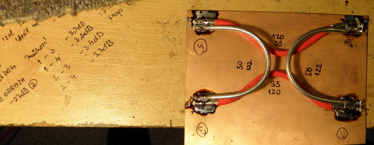
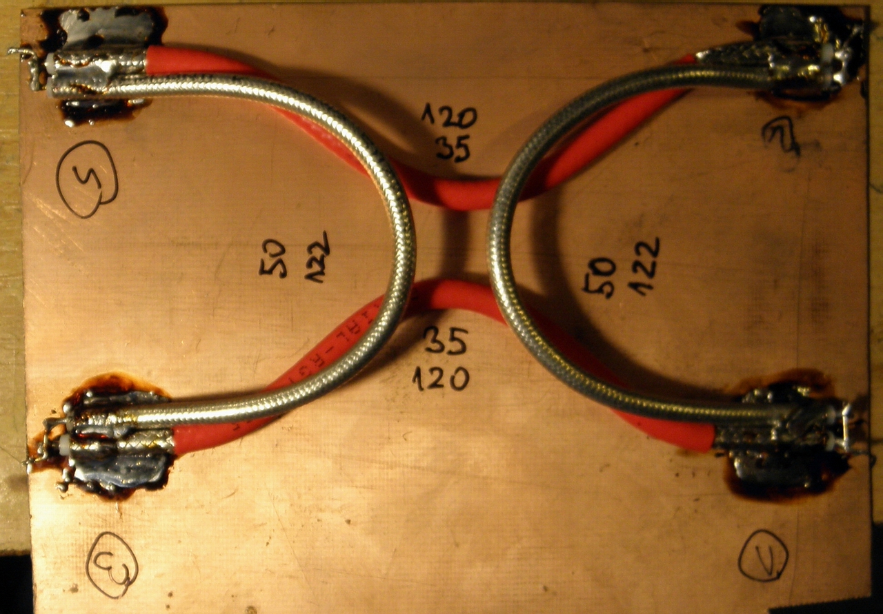
For connection of splitters and combiners, a classic 90° "branch line coupler" with 4 ports were used where one port is connected to a terminating resistor. This connection has one advantage over the often-used "Wilkinson". In case of failure of one amplifier module from a pair, half of the output of the "healthy" PA is dissipated in the terminating resistor which can be monitored (RF voltage at the terminating resistor) and trigger an alarm command to shutdown the PA to avoid damage of other circuits. In addition, this termination resistor can be placed anywhere in the PA box and the RF signal can be routed to it through a coax cable. Dividers and combiners are assembled from lambda/4 sections of Teflon coaxial cables with impedance of 50 and 35 Ohms with outer shielding diameter of about 4.1 mm. These cables are capable of transmitting up to 400 watts RF at a given frequency which suffice in this case. Besides, the cables are soldered to the carrier and cooling plate (Fs-Sn), which is air-cooled in the PA frame on the other side, so the cables don't get too warm. Picture:
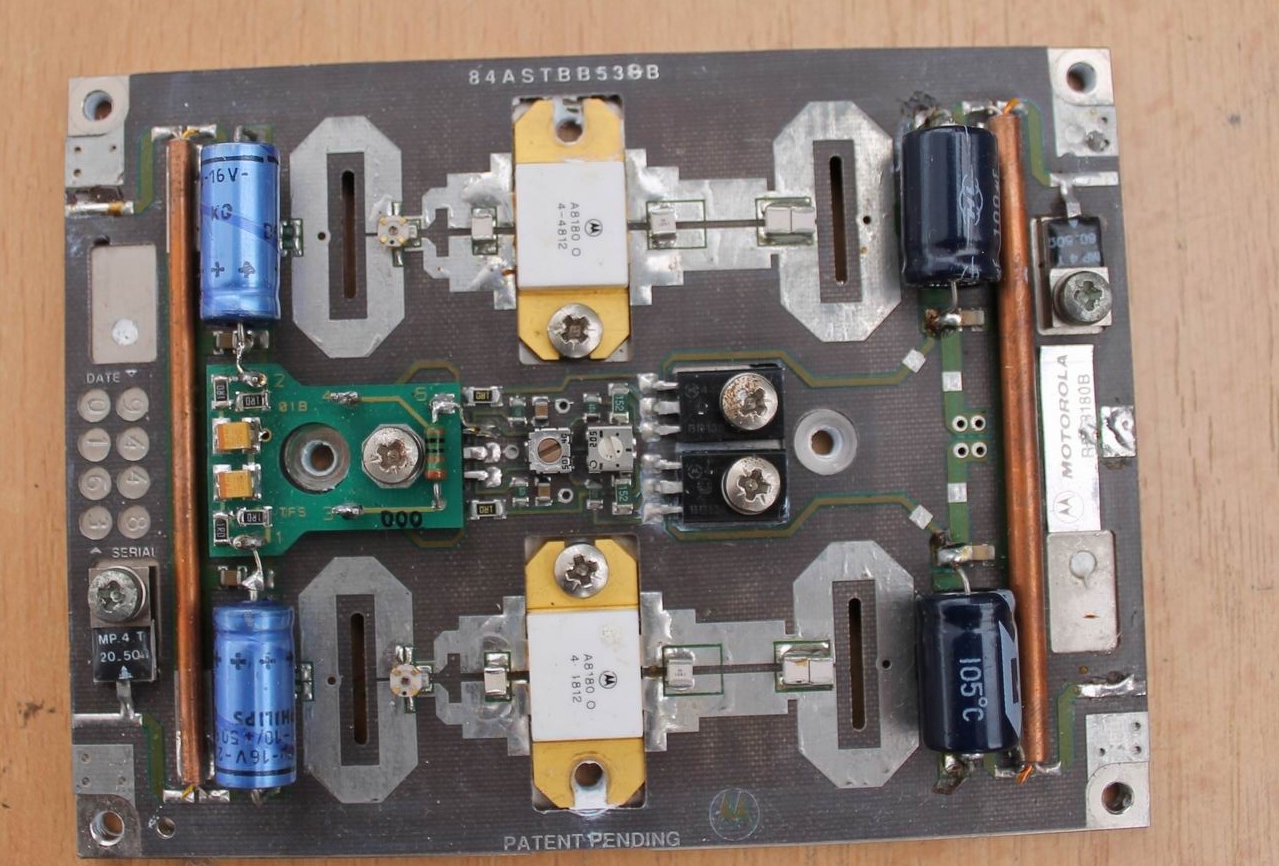
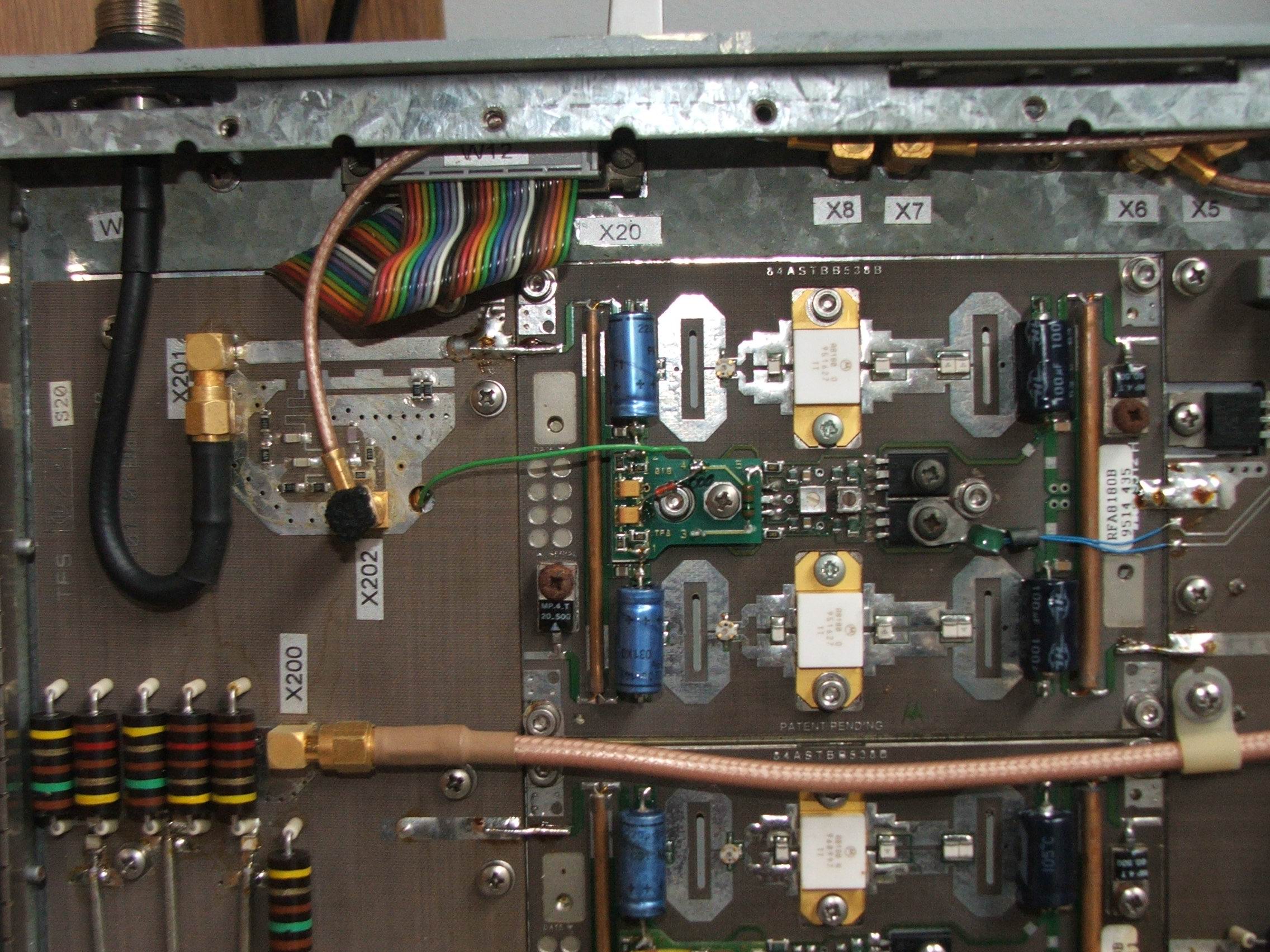
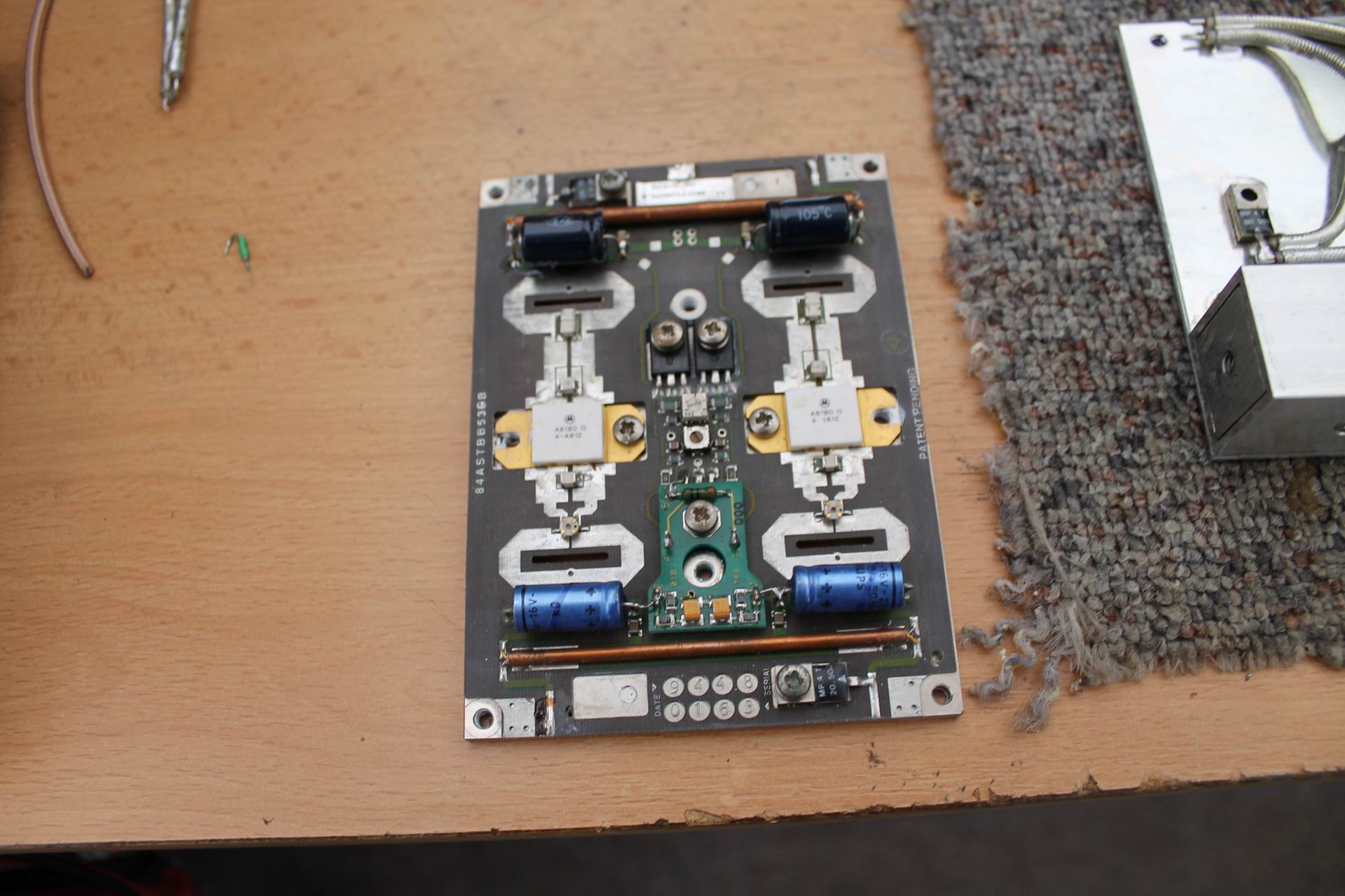
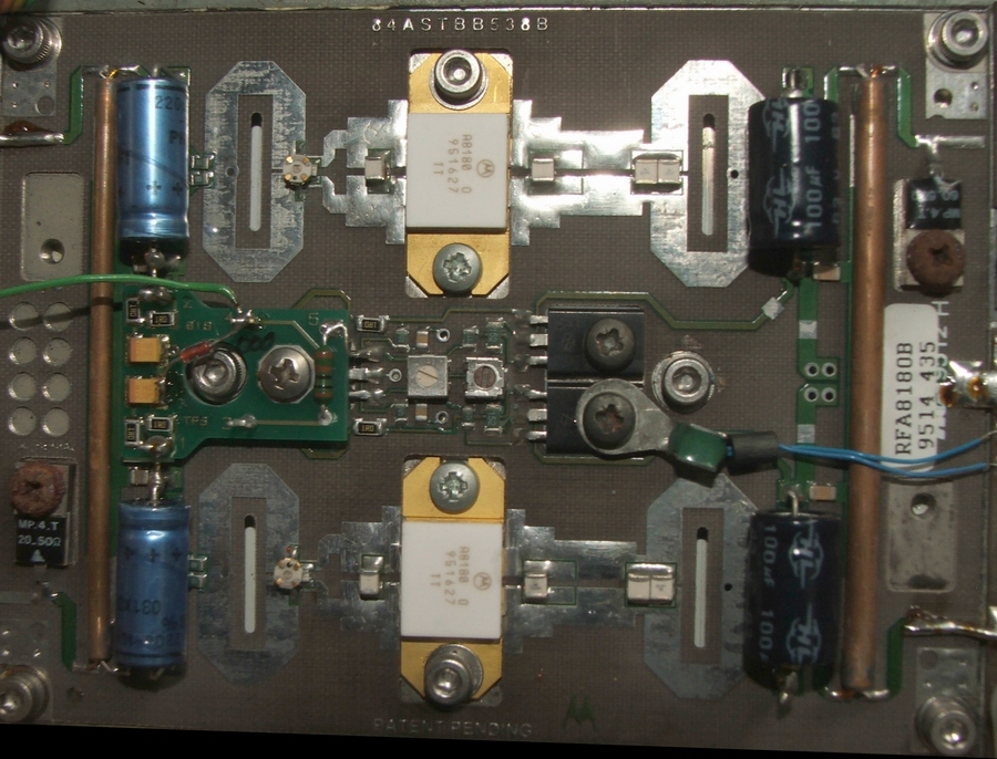
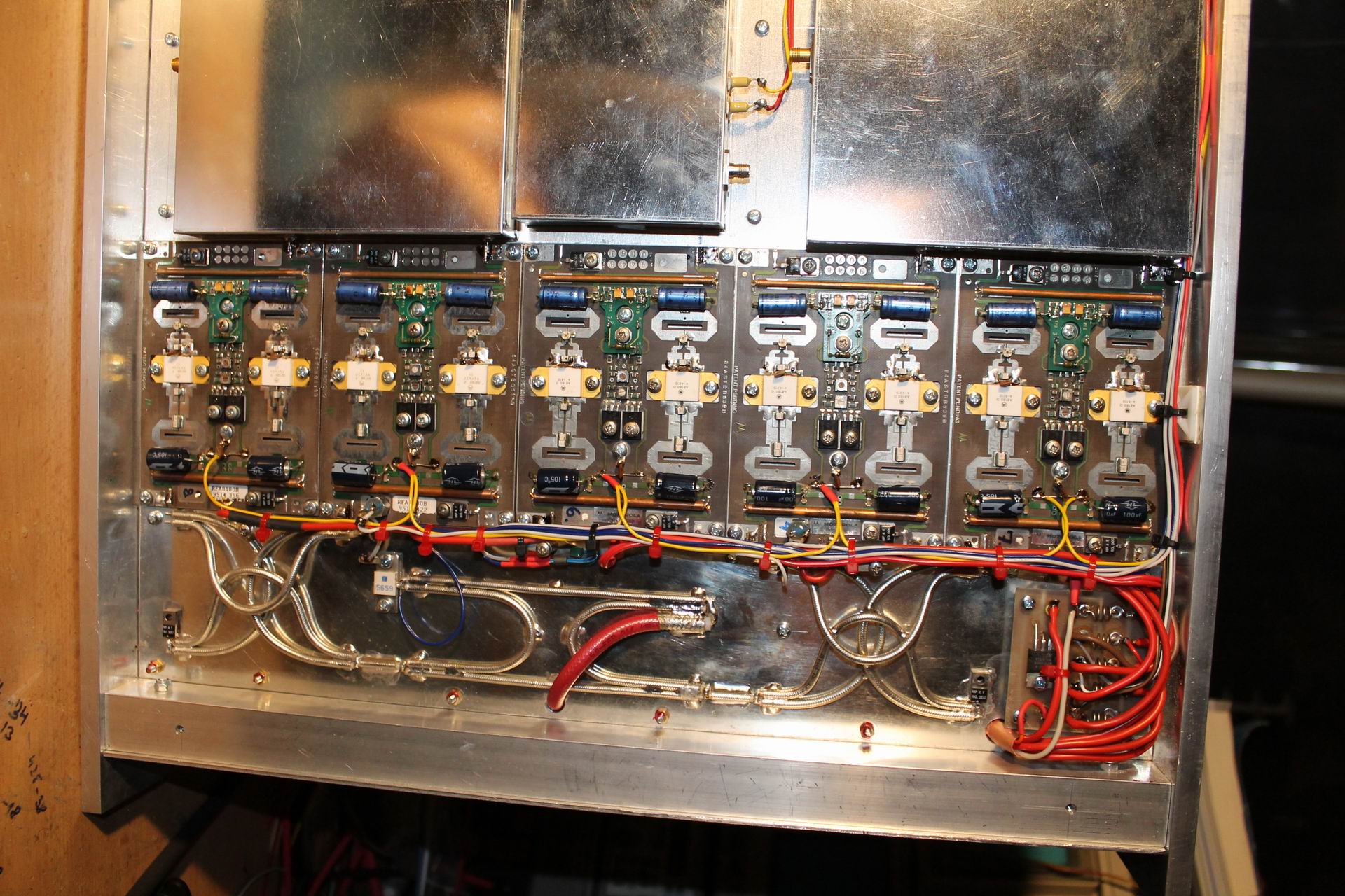
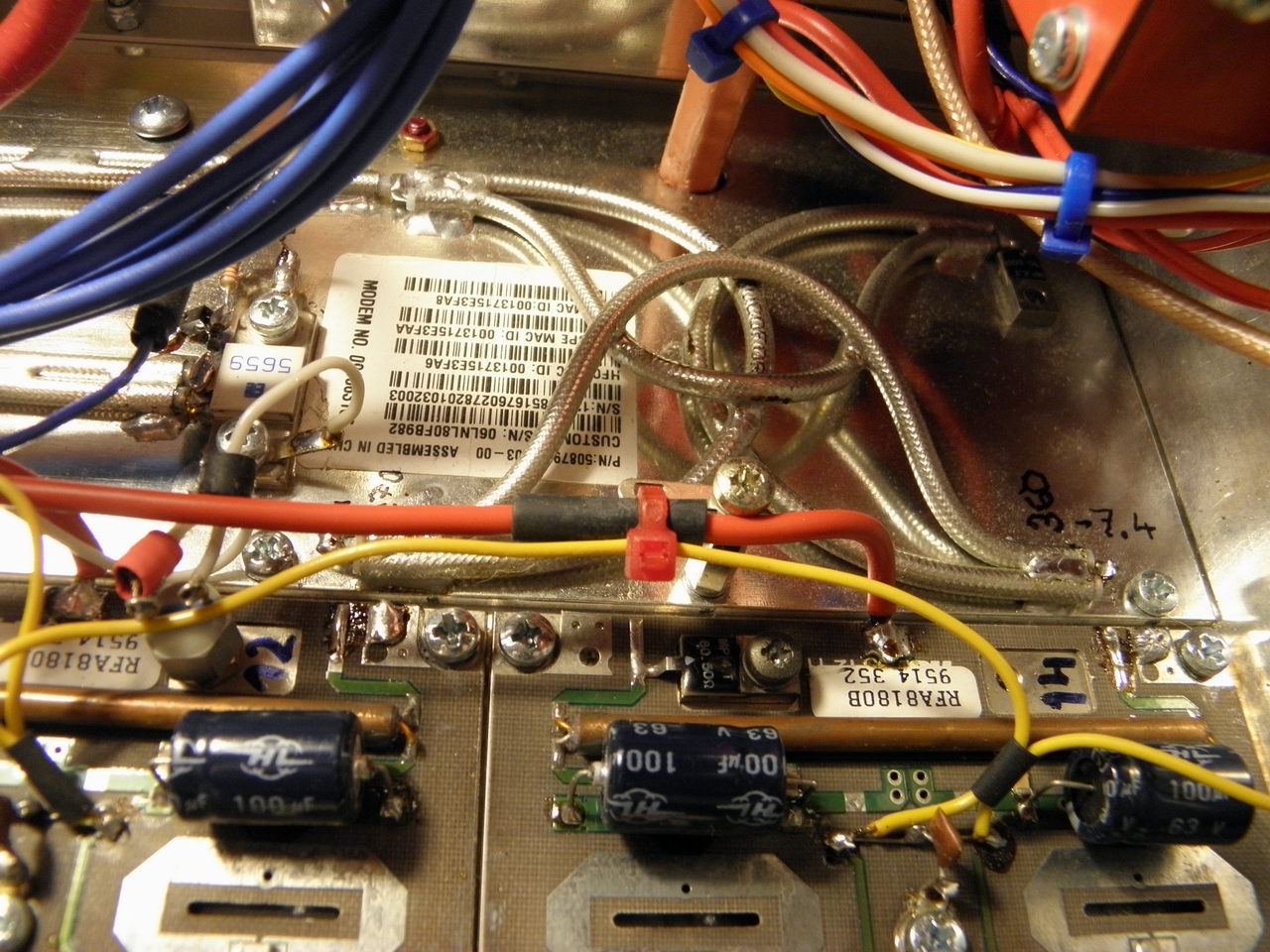
Teflon coaxial cables with a diameter of about 4.1 mm in the divider are 120 mm (for 35Ω cable) & 122 mm (for 50Ω cable) long between the ends of the shield and the inner conductor exceeds the shielding by about 1.5 mm only. A 35-ohm coaxial cable can be purchased for example here. Dividers and combiners must be plugged in properly to add and subtract the signals in phase. Wiring on this image is wrong. Correct wiring is on the scheme outlined above. If we neglect phase shifting of each amplifier module (assuming that all modules are the same), the phase shift should be 540° over each signal path. Check it carefully. For more details, see the pictures below. That's for the PA cooling and the associated basic mechanical design. Let's now take a look at the amplifier modules themselves. In our UHF TV Telefunken PA converted for the 70cm band the Motorola RFA8180B power modules originally designed for TPV 8100B transistors are used, but in this module the transistors are labeled as A8180. Does this label mean that there might be some improved transistor design that is capable of delivering more power? I do not know. More importantly, this abbreviated designation is extended by another letter, which, as observed, is related to the gain of the transistor. Therefore, transistors with the same letter should be fitted in each module. In our UHF TV PA there were transistors marked from K to R.
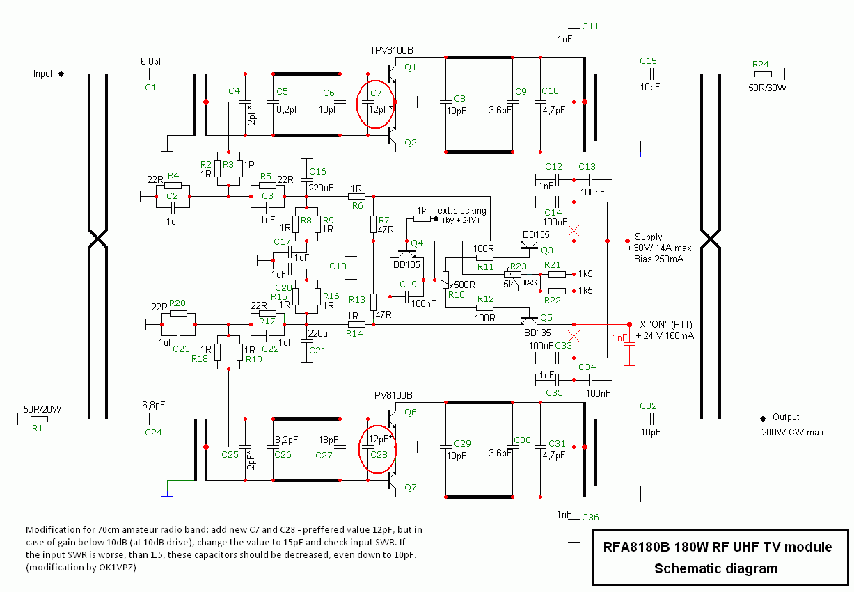
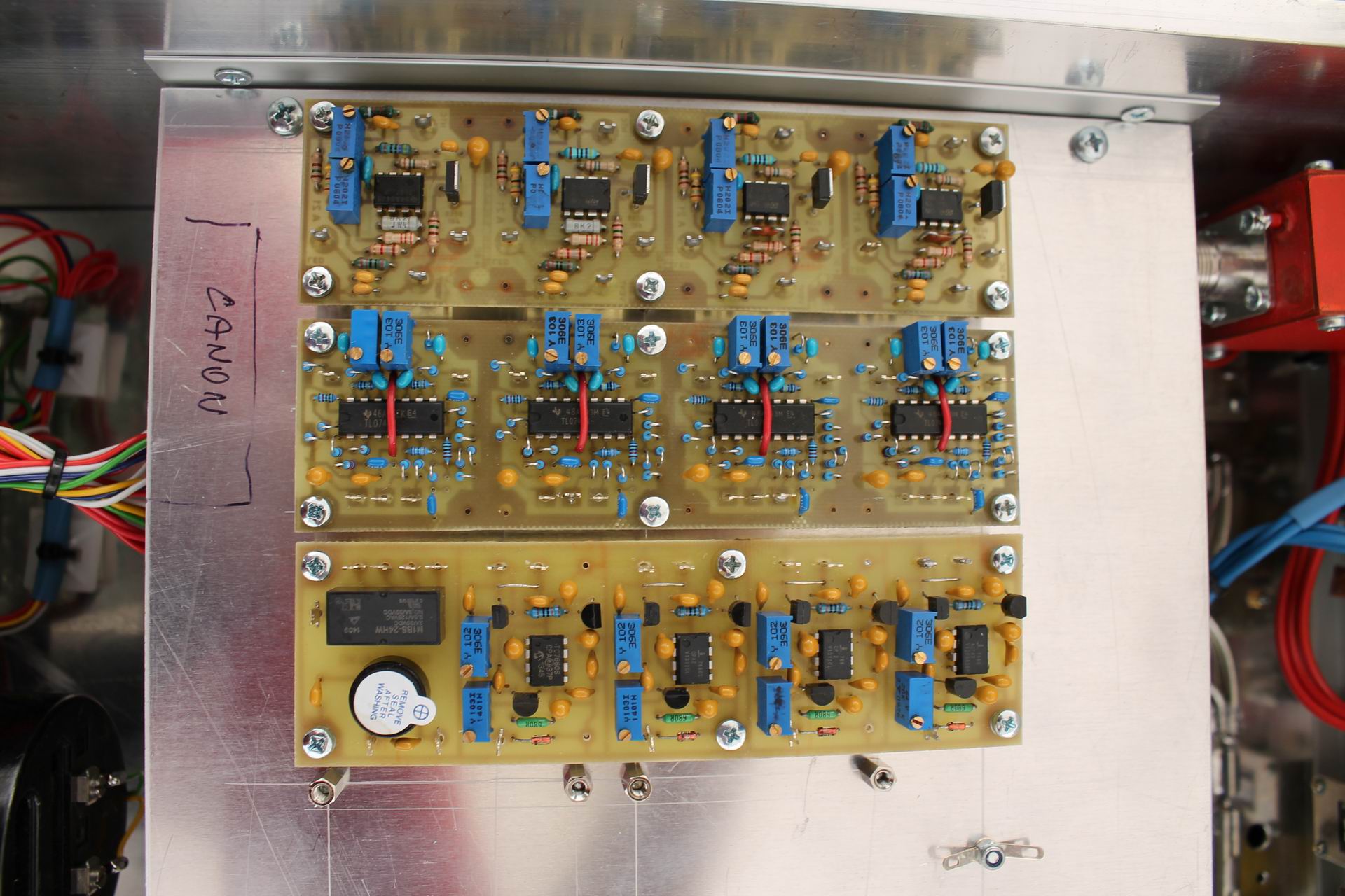
When testing these modules (14 in total) it was found out that the gain of the module at 432MHz is only about 8 to 9dB, however, the energy efficiency is good and the termination resistance of the coupler of both halves PA remains cold. Balancing the two module halves using octave Lambda/4 clusters (probably from this company) is good, and there is no need to make any changes at the transistor outputs. On the input side, a larger gain can be reached by adding an additional ceramic capacitor 12pF (NP0) between the bases of both transistors (the amplifier module is tuned in frequency downward). This increases the gain of the module to the required approximately 10.3 to 10.8dB. If you can't reach this gain (the gain tolerance of all 4 modules should be within 0.5dB) try using the capacitor 15pF instead of the 12pF especially for transistors labeled with the letters M and lower. The schematic diagram of such amplifier module, including modifications for use in the 70cm band, is here:
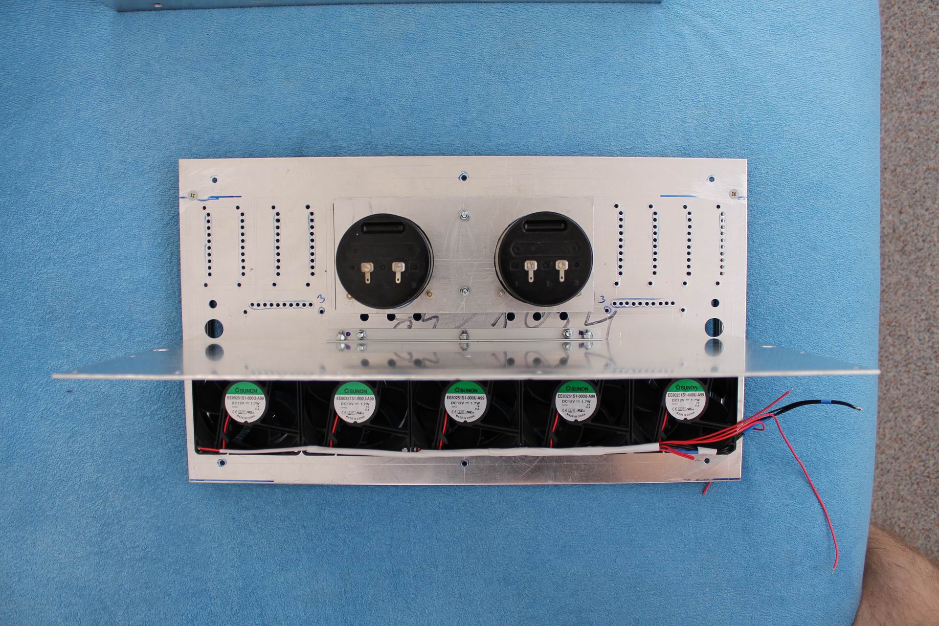
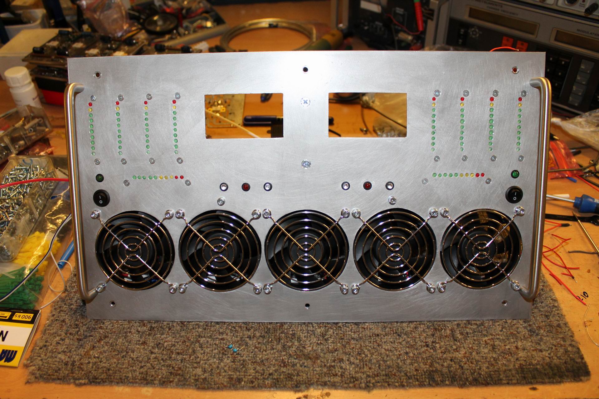
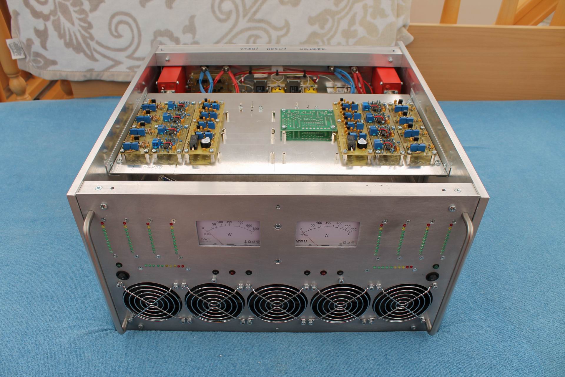
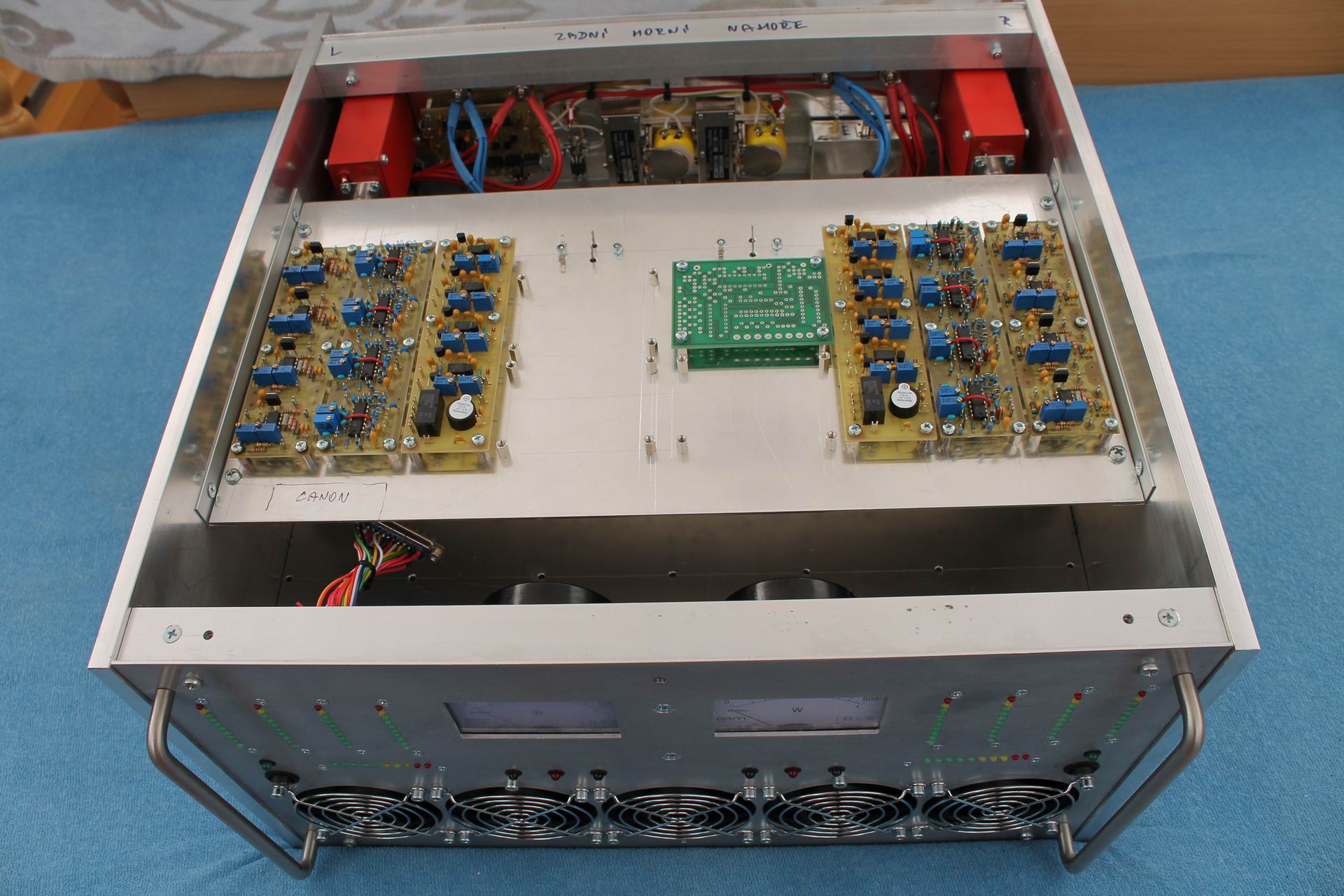
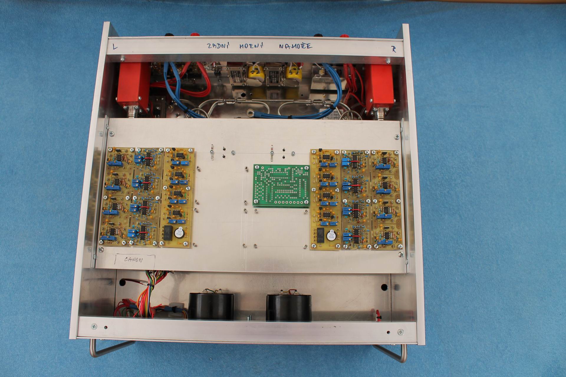
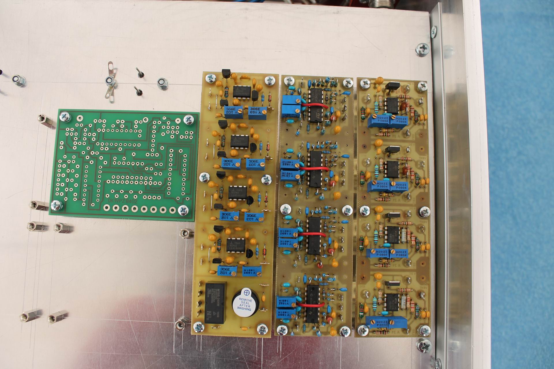
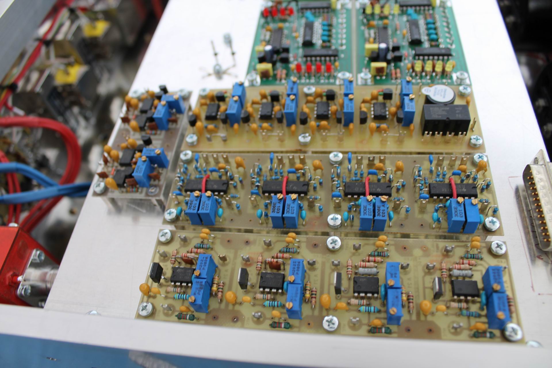
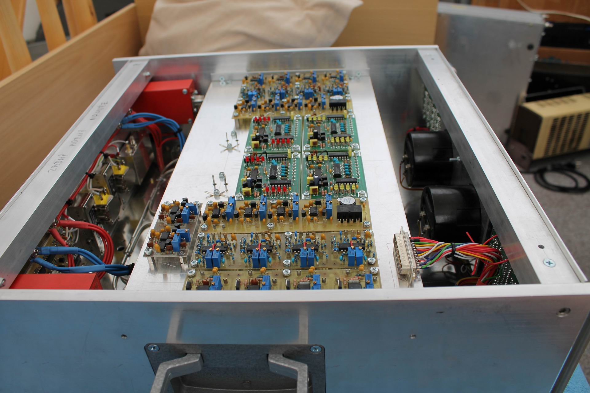
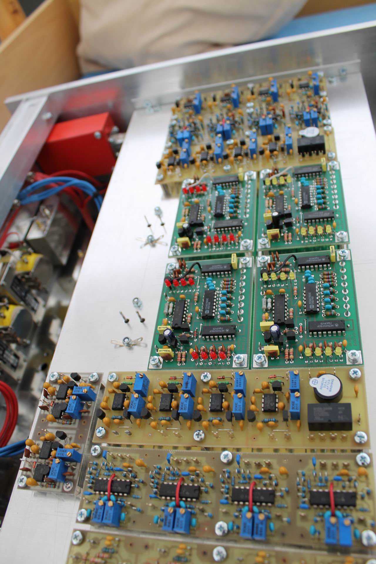
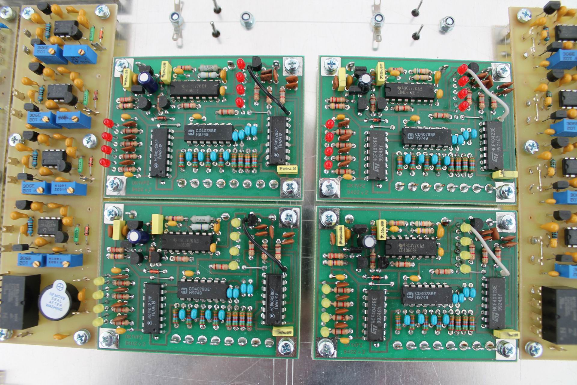
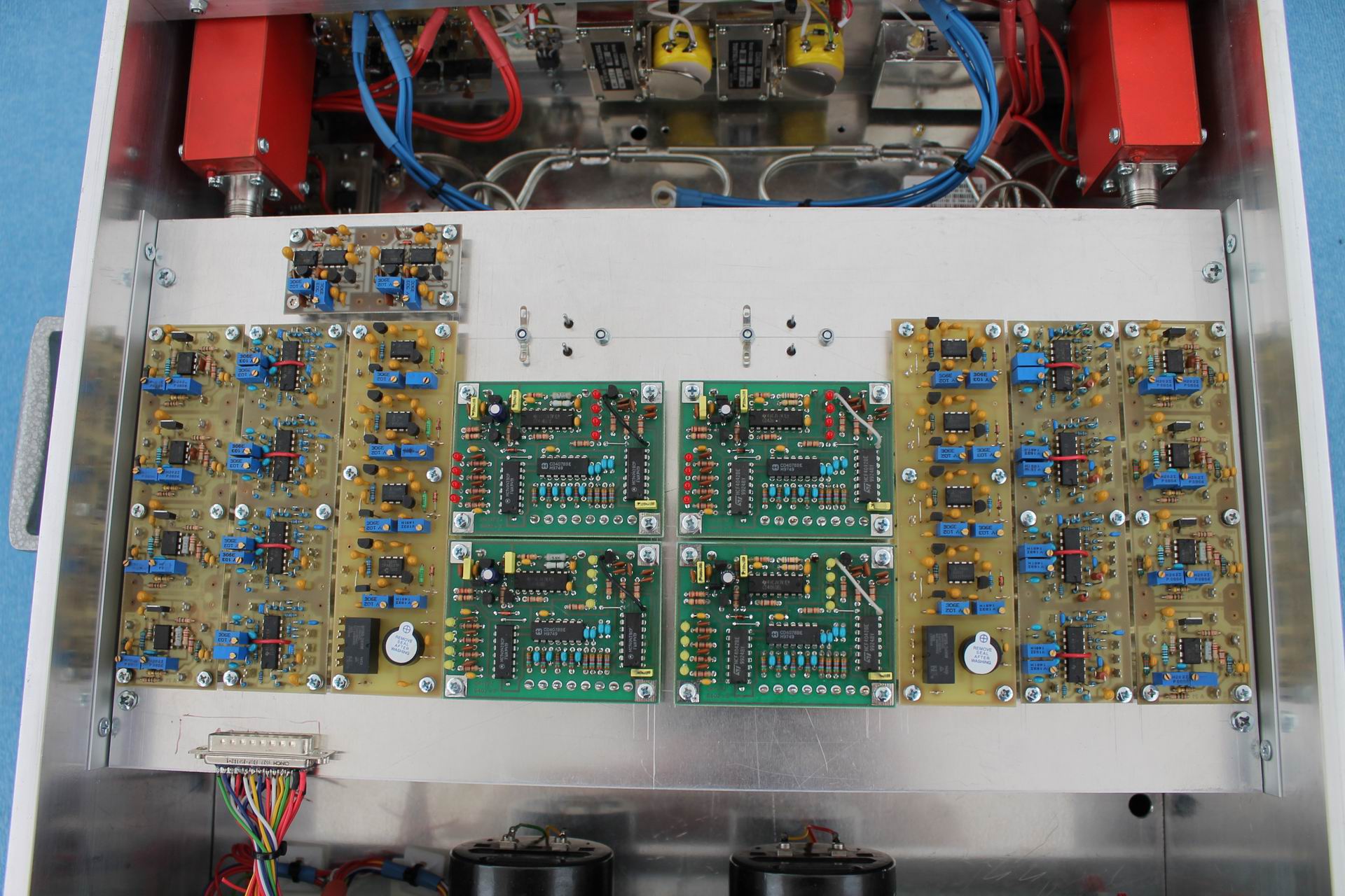
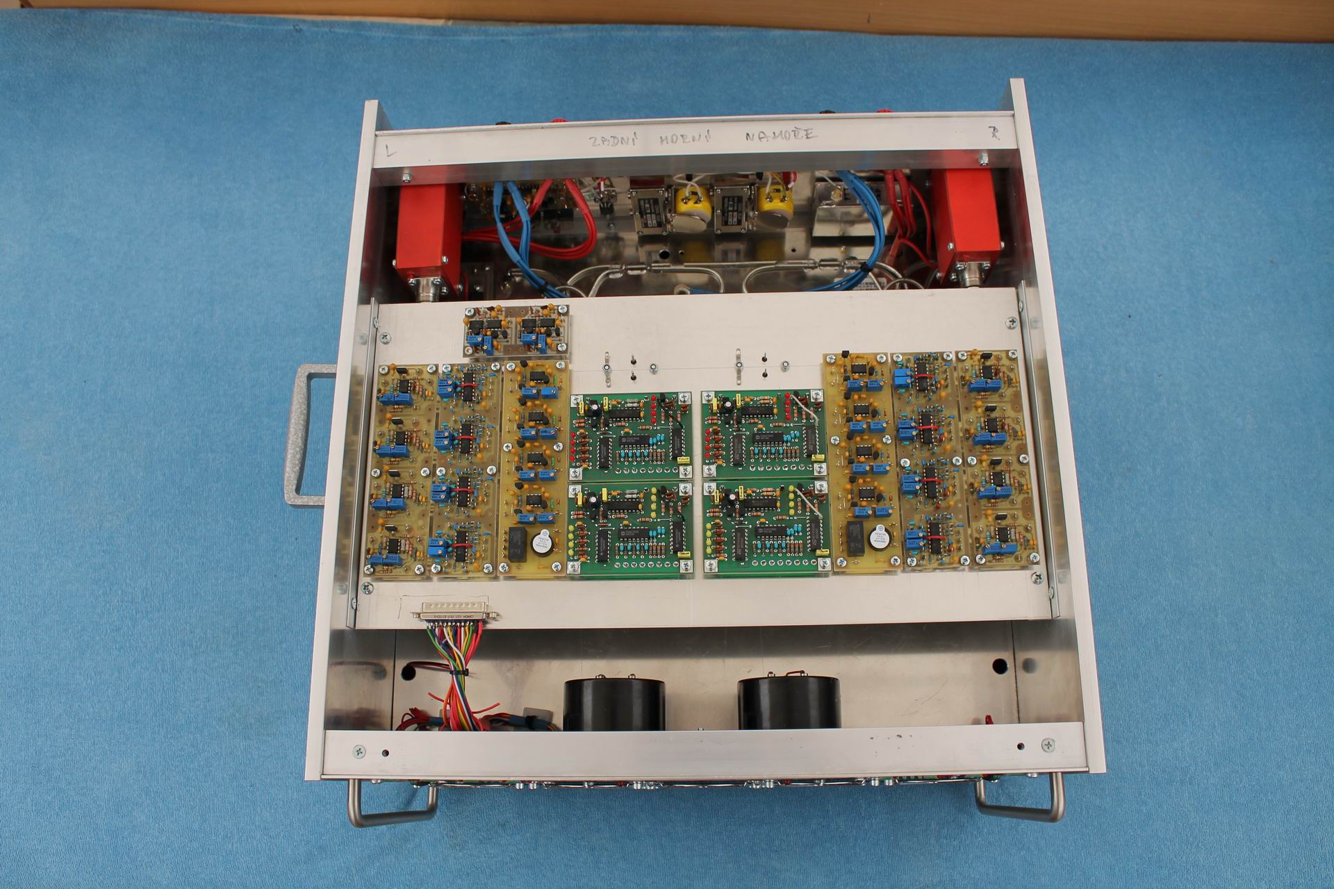
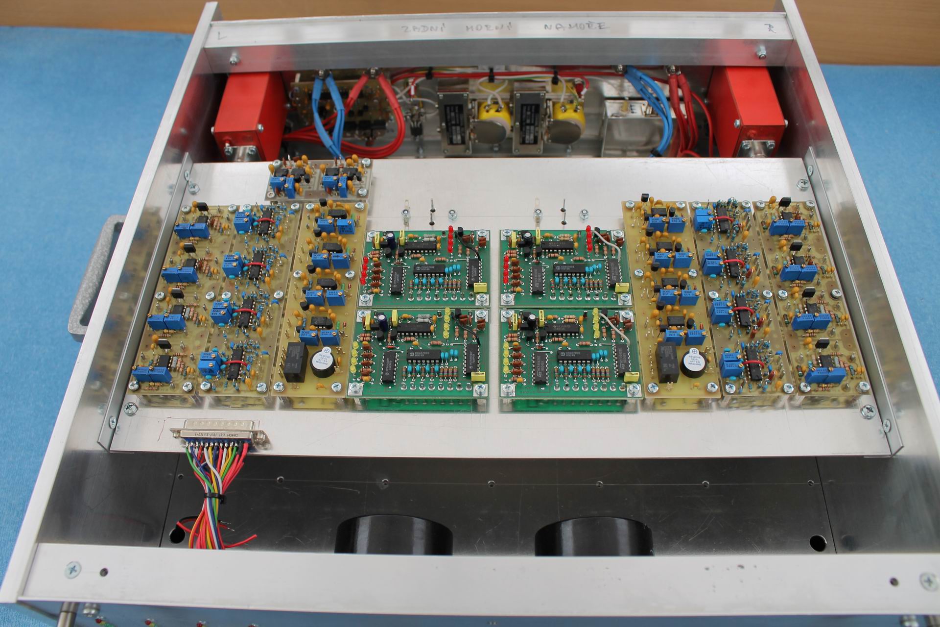
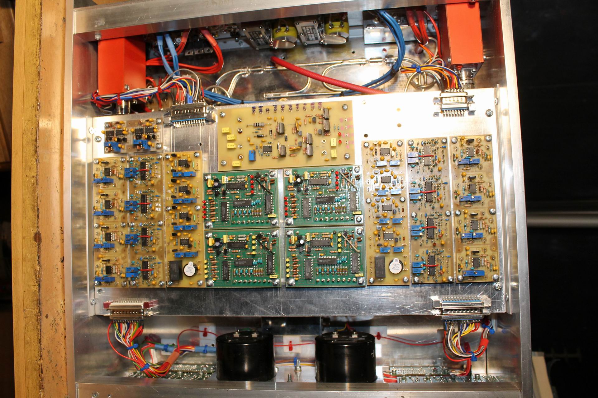
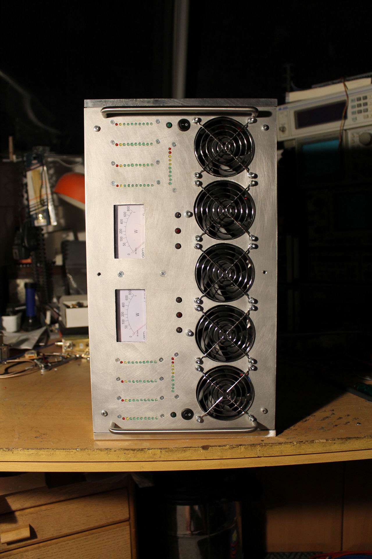
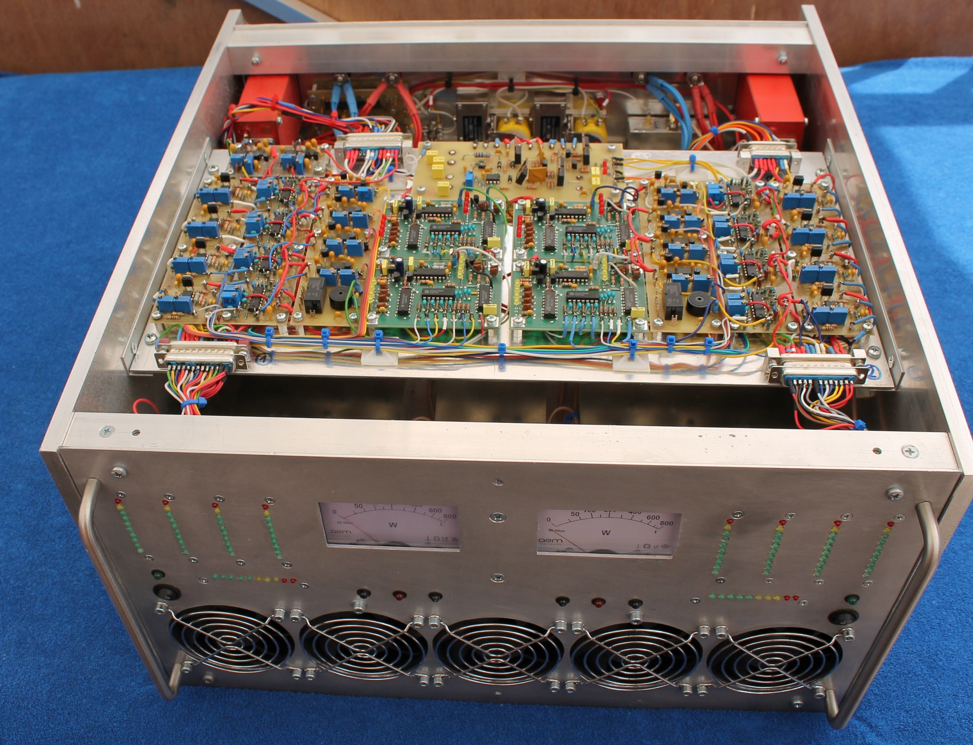
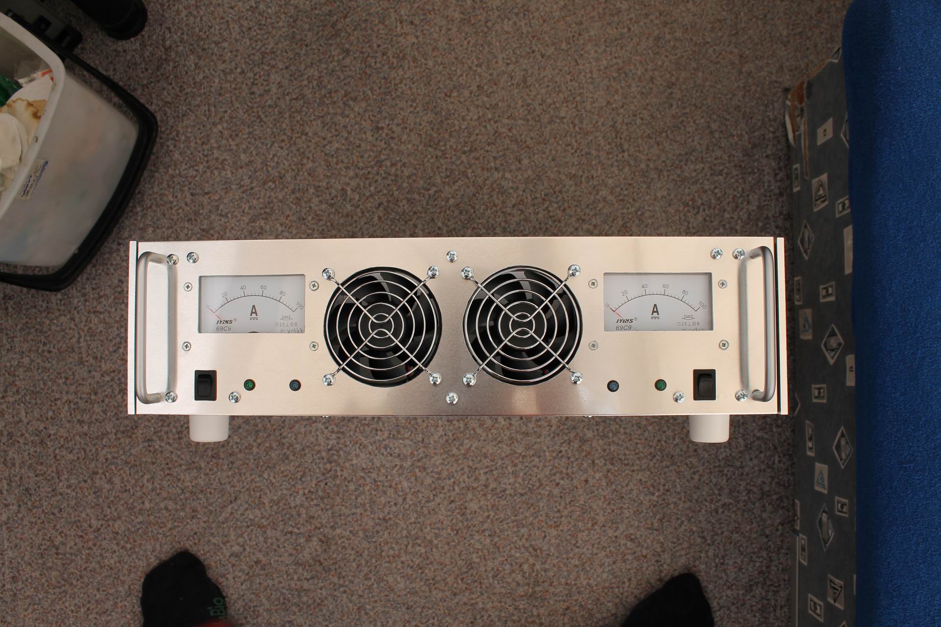
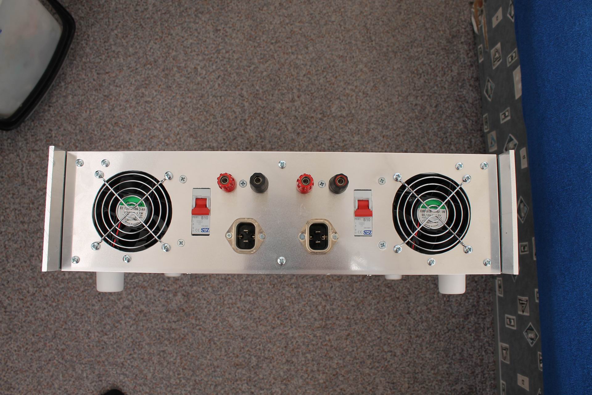
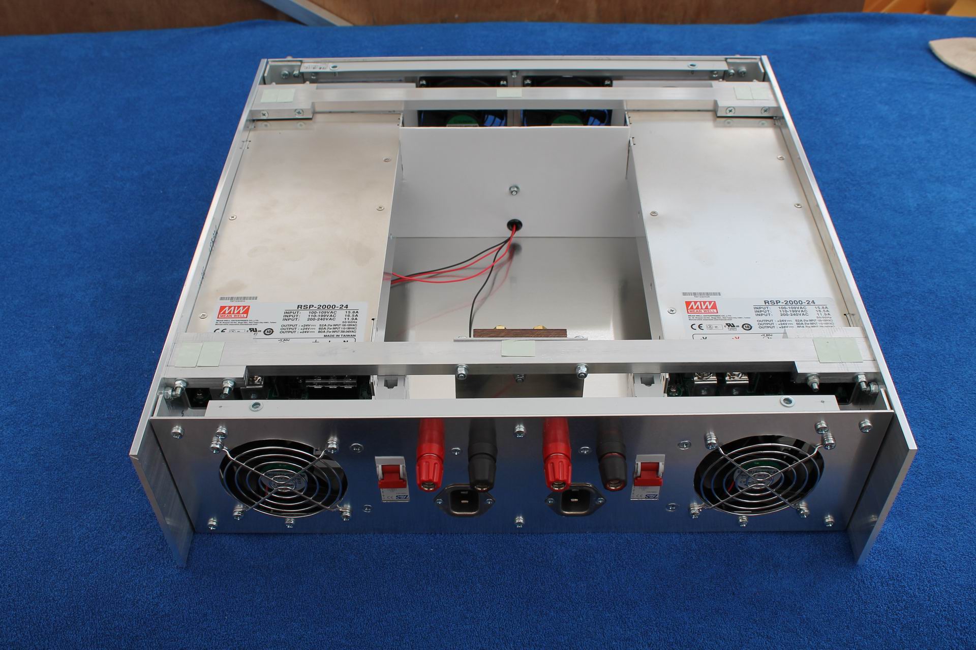
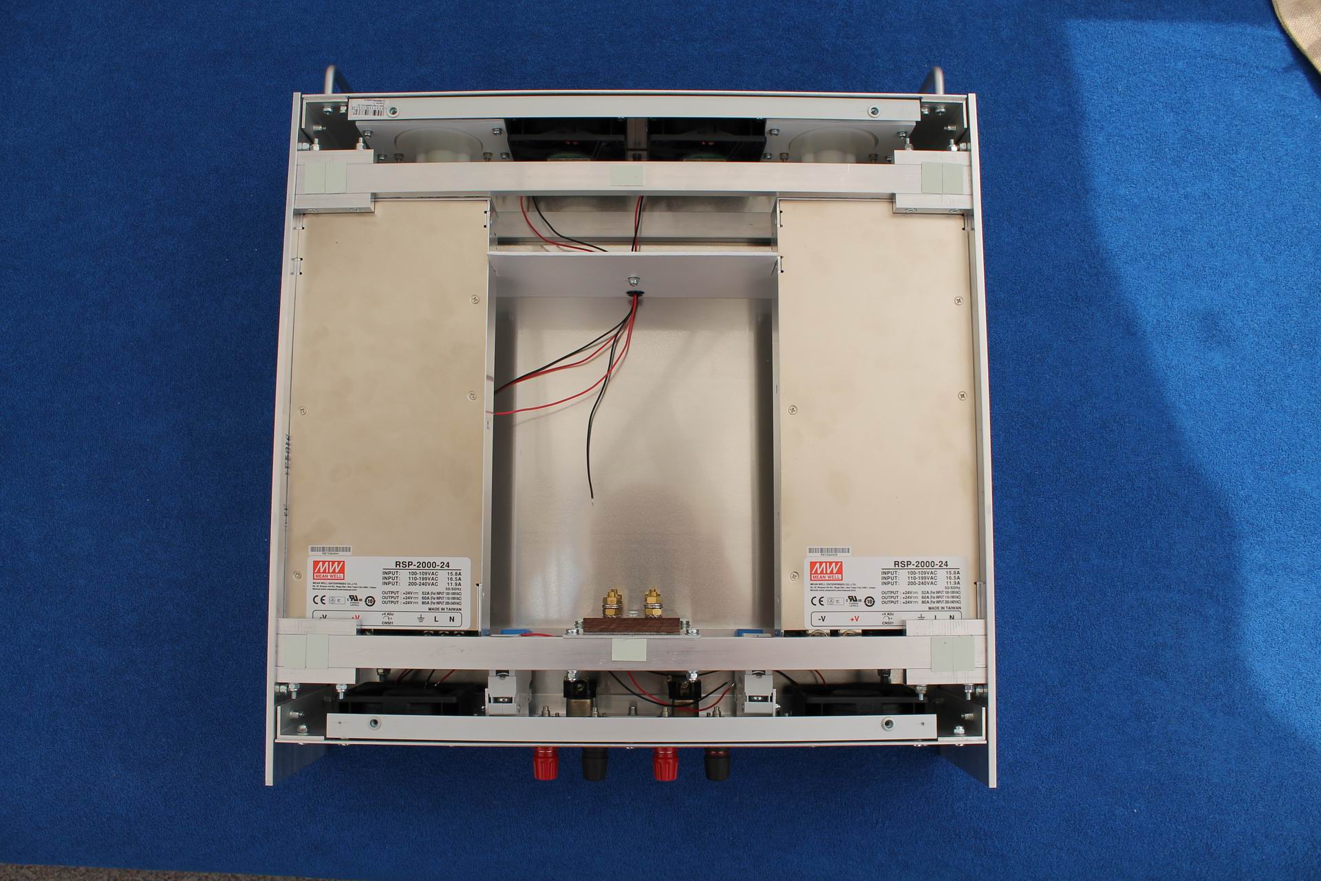
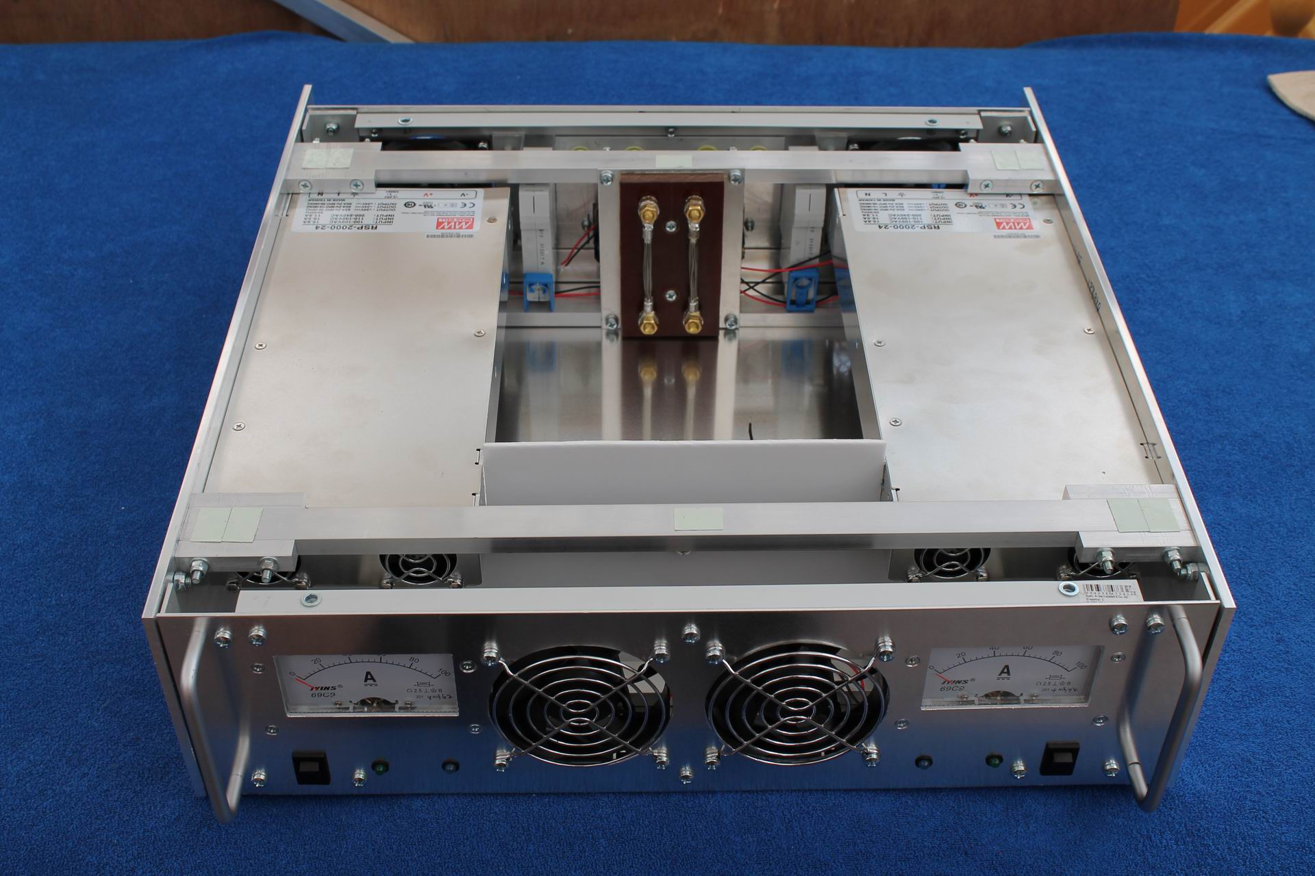
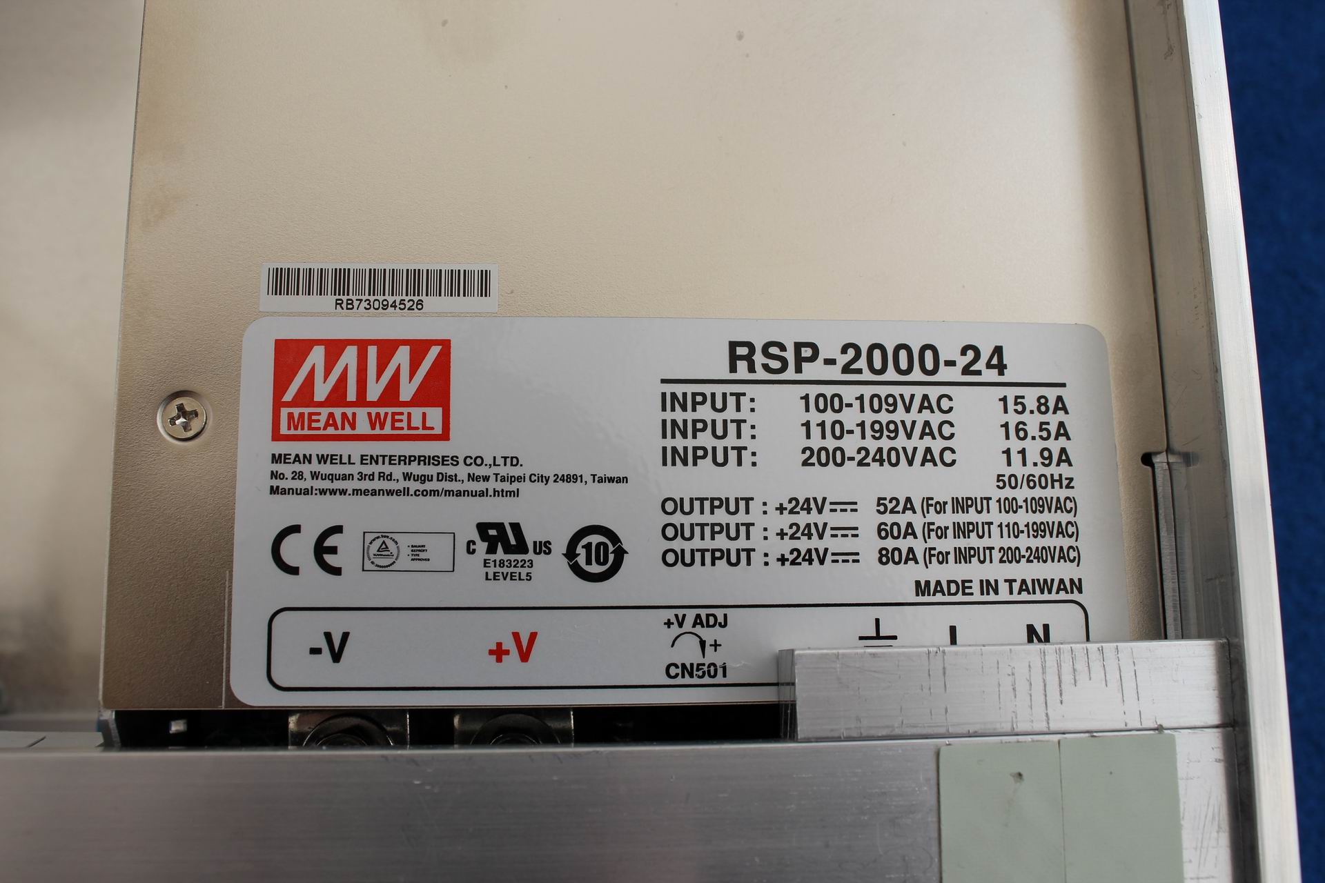
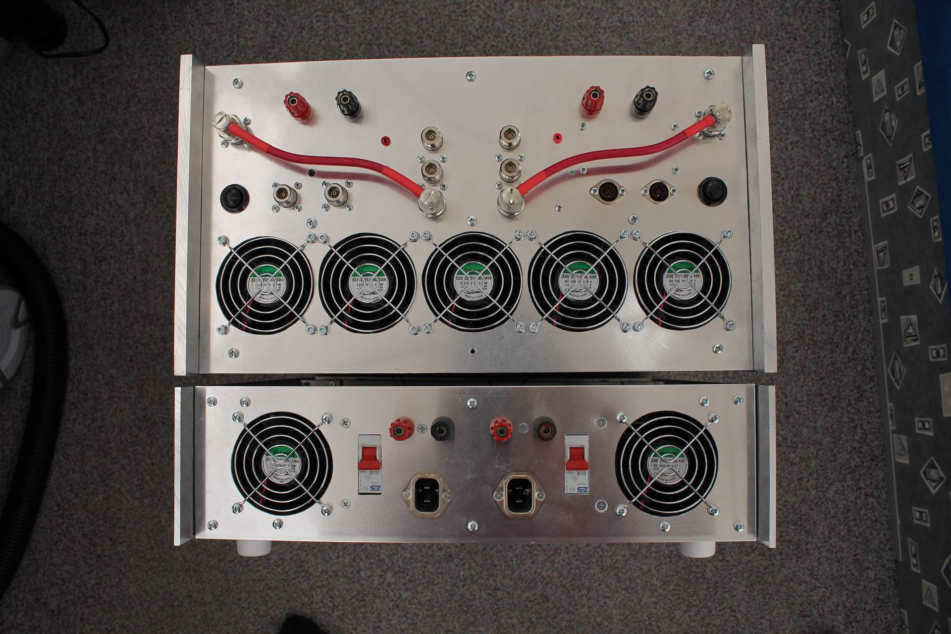
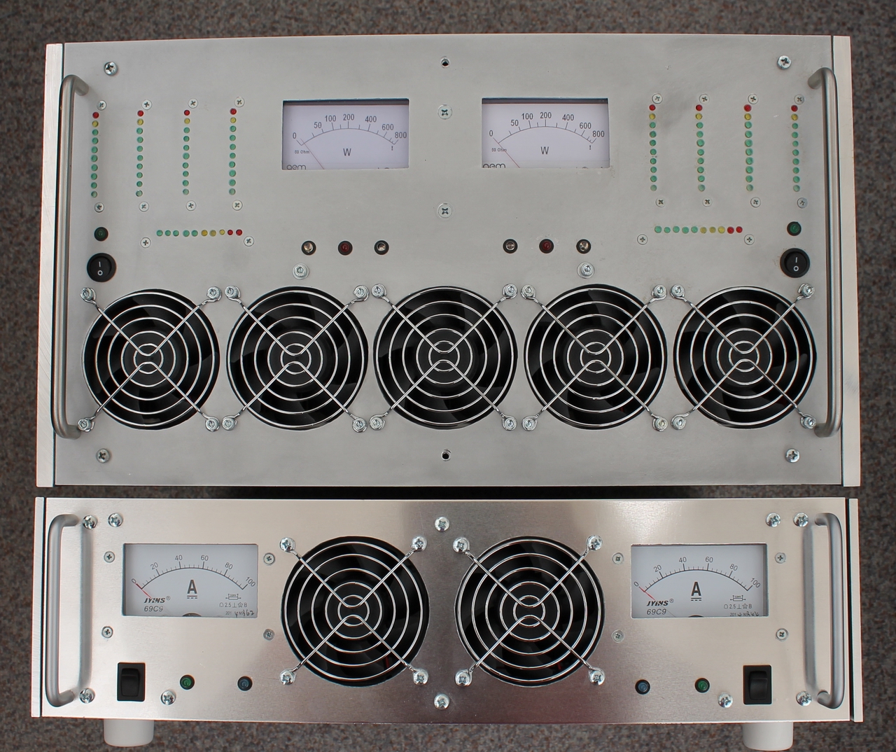
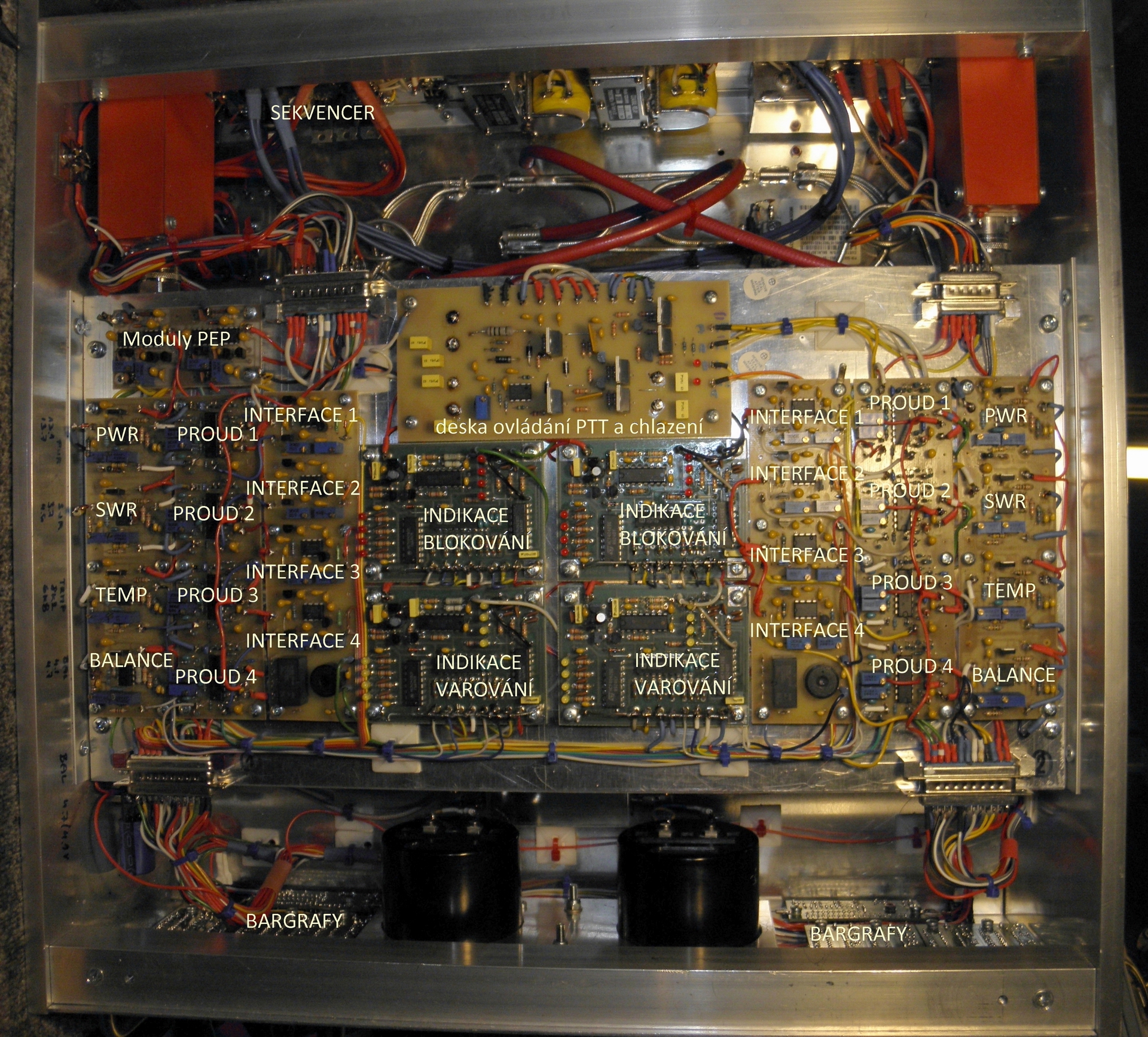
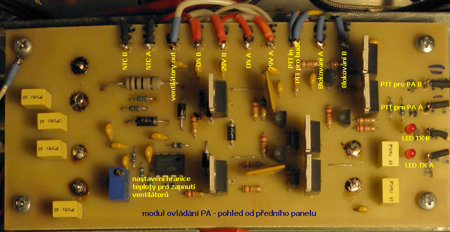
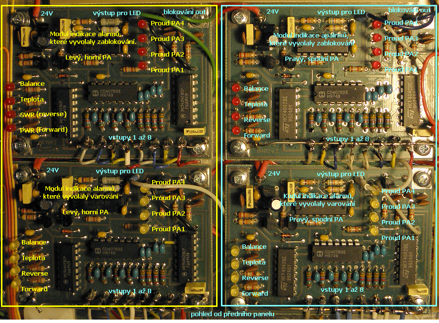
The bias current is set with the R23 trimmer to about 180mA, then set the balance of the two double-transistors with the R10 trimmer. If the transistors are properly balanced, the bias current drops to minimum. Then set the required bias current with R23 again. If the supply voltage is only 28V and the voltage for the bias circuit is only 24V like in my PA, it may be problematic to set the bias current greater than the specified 180mA. In this case, I recommend reducing the value of R23 to 1k and R21 + R22 to 680R. If the bias current can't be reached even after that, I recommend increasing of the voltage of the biasing circuit to about 26V (and ensuring that it will not drop down during PA operation). However, setting the bias current value of this amplifier module is not critical, significant worsening of 3rd order intermodulation products (and gain reduction) occurs only at the bias current less than 150mA. I eventually set bias current of about 175mA ± 5mA for all PA modules. Signal path description: Since the 70cm PA is a "twin", it has a common driver. In accordance with our "drive standard" described here, there is a coupler with coupling attenuation of about 13 to 20 dB (depending on the trimmer setting) at the input side. The signal goes then in to a two-stage amplifier (I used the UHF TV PA NEC driver) which gives approx. 15 watts of output at drive 50mW with very low IMD followed by the 90° branchline splitter 1 to 2 with outputs to PA1 and PA2. Extension cables have the same length to enable using the twin PA as a single PA with power up to 1400W (by using of an external 90° combiner). There's a driver with one UHF TV module for each PA (only one signal path is described as both PAs are identical). It is the "fifth" module in the middle between 4 "final" modules (see pictures). Its output is about 65W max. This output is splitted by 4 to create driving signal of 4 x 15W for 4 power modules. There is a 4-in-1 combiner at their outputs which gives total power of about 720W max at the combiner output. The following device is a directional coupler used for measuring of power output and antenna matching, and finally the Tohtsu antenna relay CZX3500. Note: This N-connector relay looks very good, but it's not very suitable for switching 800W power on 70cm. Occasionally the heating of the transient resistor on the RF contacts causes desoldering of the gilded contact tube at the output connector, which can "move out" a bit then and cause a short circuit (or at least the RF arc) to the ground in the relay. So be careful with this relay on 70 and 23cm band, if you intend to switch the output power greater than 600W! As nothing is perfect in the real world (the splitters and the couplers have their tolerances in the attenuation of each path (1-> 4 and 4-> 1) up to 0.5 dB i.e. the individual modules are not ideally balanced and the PA modules themselves differ in gain in about same manner) I've always assigned the module with larger gain to the input of a larger attenuator to compensate for that loss to some extent. The result is fully satisfactory. PA is able to give power of 750W at 1dB compression and spacing of IMD3 intermodulation products over 35dB when powered with 28V (28.9V with no load, there's a drop on power leads and current measuring resistors). You also may ask how to design the power supply. A three-phase 3kW (30V and 100A) switching power supply was originally used in the TV PA. However, it was big and heavy reflecting the time of its design and production. As we transport all rig to the contest place by cars, I preferred small Meanwell's as proven, state-of-the-art switching power supply unit. Description of power and control circuits. The dual PA is powered by an external power supply in a 19-inch rack (see figures below) that includes two Meanwell RSP2000 (24V/80A) power supplies. They are set to an output voltage of approx. 28.8V (maximum). In practice they give a current of up to 70A, so they work in the safe area. You can switch on or off one or both PA "halves" separately. In either case, however, both coaxial relays switch simultaneously (PA has a single sequencer) to prevent LNA damage in the case of multibeaming. Each PA has a power output meter equipped with PEP wattmeter, the temperature of the heat sink and some amplifier modules is monitored and fans speed is controlled according to the temperature. An alarm is issued and emergency shutdown made (blocking of PTT) if the PA modules get overheated. The PA is equipped with a current monitoring of all 4 end power modules on the LED bar graphs on the front panel. There's also reflectometric protection and monitoring of eventual phase unbalance of individual PA modules before merging their power. There is two-state of the PA monitoring alarm and emergency. A simple circuits displays the monitored values (alarm or emergency) by the LEDs on the front panel and a small siren sounds to report a problem to the operator. If the PA is temporarily shut down (by blocking the PTT) and the problem does not persist, PA is put into operation after about 30 seconds. The protection circuits are quite simple and their connection is trivial, so there is no need to program any microcomputers and the recovery and/or possible troubleshooting are simple as the circuitry is based on the old simple CMOS ICs. That's for description of this twin PA. Now take a look at the pictures again, because it is often more effective to see once than to read ten times... If you decide to build the solid state PA like this, I wish you a lot of fun with the building, satisfaction with its function and many DX QSOs! 73 de OK1VPZ
PS: thanks OK1DIX and OK1TEH for help with translantion of my poor English. Thanks Dirk ON5GS and his friend for data of old Telefunken PA.
|

